AMAZON multi-meters discounts AMAZON oscilloscope discounts
OBJECTIVES
• state the purpose of an across-the line magnetic starting switch.
• describe the basic construction and operation of an across-the-line starter.
• state the ratings for the maximum sizes of fuses required to provide starting protection for motors in the various code marking groups.
• describe what is meant by running overload protection.
• draw a diagram of the connections for an across-the-line magnetic starter with reversing capability.
Alternating-current motors don't require the elaborate starting equipment that must be used with direct-current motors. Most three-phase, squirrel-cage induction motors with ratings up to 10 horsepower are connected directly across the full line voltage. In some cases, motors with ratings greater than 10 horsepower also can be connected directly across the full line voltage. Across-the-line starting usually is accomplished using a magnetic starting switch controlled from a pushbutton station.
The electrician regularly is called upon to install and maintain magnetic motor starters. As a result, the electrician must be very familiar with the connections, operation, and troubleshooting of these starters. The National Electrical Code (NEC) provides information on starting and running overload protection for squirrel-cage induction motors. A comprehensive study of motor controls is covered elsewhere on this web site.
ACROSS-THE-LINE MAGNETIC STARTER
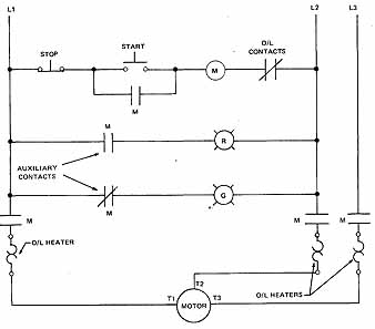
In the simplest starting arrangement, the three-phase, squirrel-cage motor is connected across full line voltage for operation in one direction of rotation. The magnetic switch used for starting, has three heavy contacts, one auxiliary contact, three motor over load relays, and an operating coil. The magnetic switch is called a motor starter if it has overload protection. Older motor starters already in service may have used two overload relays. Three overload relays are now required by the National Electrical Code in new installations.
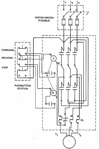
The wiring diagram for a typical across-the-line magnetic starter is illustrated in 1 A. The three heavy contacts are in the three line leads feeding the motor. The auxiliary contact acts as a sealing circuit around the normally open start pushbutton when the motor is operating. As a result, the relay remains energized after the start button is released. The four contacts of the across-the-line magnetic starter are operated by the magnetic starter coil controlled from a pushbutton station, as illustrated in 1 B.
ill 2A shows a typical pushbutton station. Two pushbuttons are housed in a pressed steel box. The start pushbutton is normally open and the stop pushbutton is normally closed, as shown in the diagram (2 B).
STARTING PROTECTION (BRANCH-CIRCUIT PROTECTION)
In fgr1A, a motor-rated disconnect switch is installed ahead of the magnetic starter. The safety switch is a three-pole, single-throw enclosed switch. It has a quick-break spring action and is operated externally. The motor circuit switch contains three cartridge fuses which serve as the starting protection for the motor. These fuses must have sufficient capacity to handle the starting surge of current to the motor. The fuses protect the installation from possible damage resulting from defective wiring or faults in the motor windings. This combination may be available in one enclosure (3). (See NEC Article 430.)
Briefly, the National Electrical Code gives the following information on starting protection for squirrel-cage induction motors.
1. The maximum size fuses permitted to protect motors are rated at 300 percent of the full-load current of the motor for nontime-delay fuses, and 175 percent for time-delay fuses.
NOTE: If the required fuse size as determined by applying the given percentages does not correspond with the standard sizes of fuses available, and if the specified over- current protection isn't sufficient to handle the starting current of the motor, then the next higher standard fuse size may be used. In no case can the fuse size exceed 400 percent of the full-load current of the motor for nontime-delay fuses and 225 percent of the full-load current for time-delay fuses. (See the National Electrical Code.)
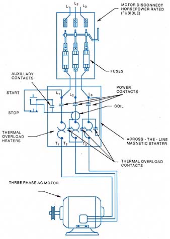
ill. 1A: A wiring diagram for an across-the-fine magnetic
starter.
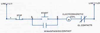
ill. 1B: Elementary diagram of the control circuit for the
starter
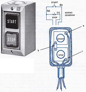
ill. 2A: Start-stop general purpose control station.
ill. 2B: A pushbutton station and wiring diagram.
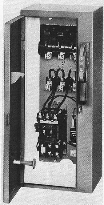
ill. 3: Combination starter with fusible disconnect switch
The marking system for squirrel-cage induction motors was developed by the National Electrical Manufacturers Association (NEMA). Note that the fuses used to protect motors with different code letter identifications varies from 150 percent to 300 percent of the rated full-load current, NEC Table 430-152. The difference is in the starting current surges and is due to differences in the design and construction of the rotor.
Rotors are constructed with different characteristics. ill 4 shows the various types of rotor construction and the associated code letter. The applications of motors with these code letters is also indicated. The design of the rotor affects the amount of current needed to produce the rotor magnetic field. Code letter A has high starting torque and relatively low starting current. The code book chart 430—7(b) will indicate that a code letter A motor will have less locked rotor kVA than other motors. This calculation indicates there is less starting current for the same voltage for a code motor. The chart in 4 gives some broad categories of motors. A, B to E, F to V.
An ac magnetic starter is illustrated in 5. The starter consists of power contacts that are used to open and close the circuit to the motor. As ac is applied to the magnetic coil, the magnet draws the contacts closed and connects the line power to the motor power. In addition to connecting the line power, the magnetic starter has an add-on block at the bottom to provide for running overload protection. See unit 16 for a detailed operation of the magnetic starter.
Example 1. A three-phase, squirrel-cage induction motor with a nameplate marking of code letter F is rated at 5 hp, 230 volts. According to the National Electrical Code, this motor has a full-load current per terminal of 15.2 amperes. The starting protection shall not exceed 300 percent of the rated current for squirrel-cage motors with nontime-delay fuses. Thus, the starting protection is 15.2 x 3 = 45.6 amperes.
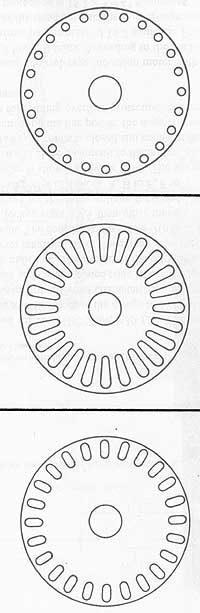
ill. 4 Various types of rotor laminations:
This type of motor has a high-resistance rotor with small rotor bars Near the rotor surface.th1s motor has a high starting torque and low Starting current. Applications: metal shears. Punch presses, and metal drawing machinery
This type of motor has a high-reactance and low-resistance rotor.
This motor has a relatively low starting current and only fair starting torque. It has larger conductors deep in the rotor iron. Applications: motor-generator sets, fans, blowers, centrifugal pumps, or any application where a high starting torque isn't required.
This type of motor has a relatively low-resistance and low-inductive reactance rotor. This motor has a high starting current and only fair starting torque. It has large conductors near the rotor surface.
Applications: motor-generator sets, fans, blowers, centrifugal pumps, or any application where a high starting torque isn't required.
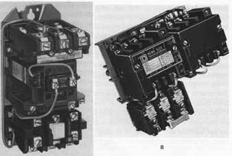
ill. 5: A) A magnetic starter includes the contactor and the overload
section. B) Ac reversing magnetic motor starter. The elementary diagram
of the starter is illustrated in 8 below.
Since a 45.6-ampere fuse cannot be obtained (see NEC Section 240-6), the next larger size of fuse (50 amperes) should be used. For motor branch-circuit protection, the motor current listed in the appropriate table of the National Electrical Code should b’ used. The full-load current, as stated on the motor nameplate, isn't used for this purpose.
RUNNING OVERLOAD PROTECTION
Many motor starters installed in the United States use a thermal-type overload assembly. The assembly is normally located beneath the contactor and is directly attached to the magnetic contactor. The overload monitoring system is designed to measure the amount of current flowing to the motor through the contactor. This is done by connecting thermal sensors called heaters in series with the motor current. The heaters are sized to produce a certain amount of heat with a specified current through them. They are calibrated to cause a thermally-operated switch to open when there is sustained heat. The heat is caused by too much current flow to the motor which indicates the motor is jammed or is working too hard and is overloaded. The thermal sensors are varied as seen in 6. The heater sensors with the associated trip-overload relays are pictured. The National Electrical Code requires the use of three thermal overload units as running over load protection. Although new installations require three overload relays, the electrician will work on many older installations which have only two overload relays. These were installed before the three overload relay requirement became effective. The overload relay unit may be either three individual units, or a common block containing the three heaters and only one trip switch contact unit reacting from any one of the heaters.
These overload heater units are made of a special alloy. Motor current through these units causes heat to be generated. In one type, a small bimetallic strip is located next to each of the two heater units. When an overload on a motor continues for a period of approximately one to two minutes, the excessive heat developed by the heater units causes the bimetallic strips to expand. As each bimetallic strip expands, it causes the normally closed contacts in the control circuit to open. The main relay coil is deenergized and disconnects the motor by opening the main and auxiliary contacts. Melting alloy over loads (solder pots) also are commonly used. The heat generated by the overload melts the solder pot to release a ratchet which trips the control circuit contacts. Many motor starters are provided with electronic overload relays. The sensors are actually current transformers that measure the exact current flowing to the motor and will provide a trip signal to the magnetic starter if the current is too high for too long.
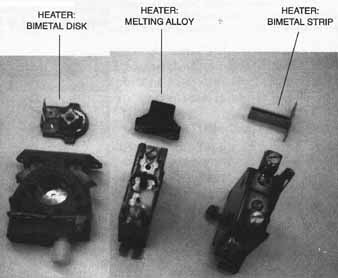
ill. 6 Thermal overload relays. Shown are the bimetal disk,
the melting alloy style and the bimetal strip. HEATER: BIMETAL DISK, MELTING
ALLOY, MELTING ALLOY
Before the motor can be restarted at the pushbutton station, the overload contacts in the control circuit must be allowed to cool before being reclosed (reset). When the reset button in the magnetic starter is pressed, the overload contacts in the control circuit are reset to their normally closed position. The motor then can be controlled from the push button station.
The National Electrical Code requires that the running overload protection in each phase be rated at not more than 125 percent of the full-load current rating for motors which are marked with a temperature rise of not more than 40 degrees Celsius (see NEC Article 430, Part C).
Example 2. Using the motor full-load current rating from the nameplate data, determine the running overcurrent protection for a three-phase, 5-hp, 230-volt squirrel-cage induction motor with a rated full-load current of 14.5 amperes and a temperature rise of 40 degrees Celsius. The running overcurrent protection is 14.5 x 1.25 = 18.1 amperes.
For this motor, heater overload units rated to trip at 18.5 amperes are required for the magnetic starter. Where the overload relay so selected isn't sufficient to start this motor, the next higher size overload relay is permitted, but not to exceed 140 percent of the motor full-load current rating. Actual motor nameplate currents are used to establish the over load protection.
AUXILIARY CONTACTS
In addition to the standard contacts, a starter may be provided with externally attached auxiliary contacts, sometimes called electrical interlocks (7). These auxiliary contacts can be used in addition to the holding circuit contacts, and the main or power contacts which carry the motor current. Auxiliary contacts are rated to carry only control circuit currents of 0-15 amperes, not motor currents. Versions are available with either normally open or normally closed contacts. Among a wide variety of applications, auxiliary contacts are used to:
• control other magnetic devices where sequence operation is desired.
• electrically prevent another controller from becoming energized at the same time (such as reverse starting), called interlocking.
• make and break circuits of indicating or alarm devices, such as pilot lights, bells, or other signals.
Auxiliary contacts are packaged in kit form, and can be added easily in the field.
ACROSS-THE-LINE MOTOR STARTER WITH REVERSING CAPABILITY
The direction of rotation of a squirrel-cage induction motor must be reversed for some industrial applications. To reverse the direction of rotation of 3 phase motors interchange any two of the three line leads.
ill. 7: Electrical interlocks (auxiliary contacts) switch
pilot lights in this circuit.
ill 8 is an elementary wiring diagram of a motor starter having a reversing capability. When the three power reverse contacts are closed, the phase sequence at the motor terminals is different from that when the three power forward contacts are closed. Two of the line leads feeding to the motor are interchanged when the three reverse power contacts close.
The control circuit has a pushbutton station with Forward, Reverse, and Stop push buttons. The control circuit requires a mechanical and an electrical interlocking system provided by the push buttons. Electrical interlocking means that if one of the devices in the control circuit's energized, the circuit to a second device is open and cannot be closed until the first device is disconnected. Mechanical interlocks, shown by the broken lines in 8, are used between the forward and reverse coils and pushbuttons.
Note in 8 that when the forward pushbutton is pressed, it breaks contact with terminals 4 and 5, opening the reverse coil circuit, and makes contact between terminal contacts to open. As the reverse pushbutton is depressed farther, it closes the contact between terminals 5 and 6 and energizes coil R. All reverse contacts are now closed and the motor rotates in the reverse direction. If the stop button is pressed, the contact between terminals 3 and 4 is opened, the control circuit's interrupted, and the motor is disconnected from the three-phase source. The National Electrical Code requirements for starting and running overload protection which apply to the across-the-line motor starter also apply to this type of motor starter.
ill 8 and 9 are actually the same motor controller. ill 8 is drawn in an elementary diagram. It has the control circuit in a schematic style, which shows the electrical relationship of the components. It shows the power contact of the magnetic starter below the schematic, and the electrical relationship of the motor control components. ill 9 shows the same components, but in the approximate physical location of the components. This style of thawing is called a wiring diagram. Many electricians find it's easier to wire a panel from the wiring diagram as it shows physical location as well as general wire routing. Many electricians find it easier to troubleshoot from a schematic, or elementary diagram, as it shows electrical sequence of operation more clearly. It is important that you know how to read both types of drawing and be able to transfer from one to the other.
DRUM REVERSING SWITCH
A drum reversing switch (10A) may be used to reverse the direction of rotation of squirrel-cage induction motors.
The motor is started in the forward direction by moving the handle of the drum reversing switch from the off position to the forward (F) position. The connections for this drum controller in both the forward and reverse positions are illustrated in 11. In the forward position, the switch connects line 1 to motor terminal 1, line 2 to motor terminal 2, and line 3 to motor terminal 3.
To reverse the direction of rotation, the drum switch handle is moved to the reverse (R) position. In the reverse position, line 1 is still connected to motor terminal 1. How ever, line 2 is now connected to motor terminal 3, and line 3 is connected to motor terminal 2. When the handle of the drum switch is moved to the off position, all three line leads are disconnected from the motor.
ill. 9: A panel or wiring diagram of an across-the-line magnetic
starter with reversing capability.
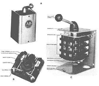
ill. 10 A) Reversing drum switch B) A bakelite section of
a drum switch C) Bakelite section with cover removed.
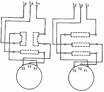
ill. 11 Connections for a drum reversing switch. Left, reverse-right,
forward.
SUMMARY
Many squirrel-cage motors are started with across-the-line motor starters. The motor and branch circuit should include short-circuit protection such as fuses or circuit breakers. The motor must also have running-overload protection. This protection is usually found with the starter and is in the form of thermal-overload heaters and the associated overload relay. The overload relay is designed to open the control circuit to the motor starter in the event of a sustained overload on the motor. Motors can be automatically controlled through the use of a magnetic starter or may be manually controlled thorough the use of a drum-type controller. In either case, a three-phase motor may be reversed by interchanging two of the three-line connections to the motor.
REVIEW / QUIZ:
1. What is the purpose of starting protection for a three-phase motor?
2. What is the purpose of running overload protection for a three-phase motor?
3. What is meant by the code letter markings of squirrel-cage induction motors?
4. List some of the industrial applications for squirrel-cage induction motors with code letter classification A. __________
5. List some of the industrial applications for squirrel-cage induction motors with code letter classifications B to E. _______
6. List some of the industrial applications for squirrel-cage induction motors with code letter classifications F to V. _________
7. A three-phase motor (code letter J) has a full-load current rating of 40 amperes, and a temperature rise of 40°C.
a. What are the maximum size fuses that can be used for branch-circuit protection?
b. What size heaters would be used for running overcurrent protection?
8. What is the maximum starting protection allowed by the National Electrical Code?