AMAZON multi-meters discounts AMAZON oscilloscope discounts
Objectives:
• describe the purpose of an alternator
• describe the ways in which the field of an alternator is established and how the alternator operates
• explain the operation of the field discharge circuit
• state how the frequency of an alternator can be determined and give the formula for calculating the frequency
• explain how voltage control for an alternator is accomplished
• describe the structure and operation of a rotating-field alternator
• diagram alternator connections
• explain three-phase voltages
An alternator is a machine designed to generate alternating current (ac). This machine is the major electrical unit in power plants.
The alternator converts to electrical energy the mechanical energy of a prime mover such as a diesel engine, steam turbine, or water turbine. Another prime mover which has become increasingly important in the generation of electricity is the power of wind.
THREE-PHASE VOLTAGES
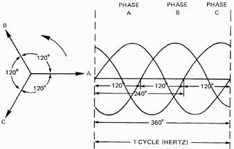
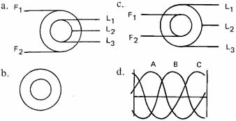
Ill. 1 Electrical displacement and generation of a three-phase
voltage
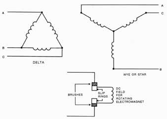
Ill. 2 Three-phase internal generator connections and a stationary
armature with a rotating dc field.
Three-phase is the most common polyphase electrical system. Poly means more than one. It is, in this instance, a system having three distinct voltages that are out of step with one another. There are 120 degrees between each voltage. Ill. 1 shows sine waves taken on an electrical oscillo-graph instrument trace. This display shows the voltage relationships of the windings. This can be taken at any point in a three-phase system. The three phases are generated by placing each phase coil in the alternator 120 degrees apart, mechanically. A rotating dc magnetic field will then cut each phase coil in succession, inducing a voltage in each armature coil, out of step with each other. Armatures are the electrical components of the ac generator that have voltage induced in them. Armatures may be either the rotating piece of the alternator or the stationary component of the alternator. These armature coils may be connected internally or externally in a delta or a wye (star) connection. Rotating fields are more commonly used than stationary fields because generating large amounts of current would require larger sizes of conductors and iron to rotate. Therefore, it's more practical to make the armature stationary.
Wye (star) and delta connections are shown in Ill. 2. These connections are shown in more detail under the heading of transformers.
ALTERNATOR TYPES
Two principal types of synchronous alternators are: (1) the revolving-armature alternator and (2) the revolving-field alternator.
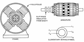
Ill. 3 Parts of an alternator of the revolving-armature type
Ill. 3 illustrates an alternator with a stationary field, a revolving armature, and the elementary wiring symbol for a three-phase alternator. The armature consists of the windings into which current is induced. The magnetic field for this type of alternator is established by a set of stationary field poles mounted on the periphery of the alternator frame. The field flux created by these poles is cut by conductors inserted in slots on the surface of the rotating armature. The armature conductors are arranged in a circuit which terminates in slip rings. Alternating current induced in the armature circuit's fed to the load circuit by brushes which make contact with the slip rings.
The revolving-armature alternator generally is used for low-power installations. The fact that the load current must be conducted from the machine through a sliding contact at the slip rings poses many design problems at higher values of load current and voltage. One alternator design has semiconductor rectifier diodes installed on the exciter field, thus eliminating the brushes and sliprings for the revolving field alternator (see Brushless Generators).
FIELD EXCITATION
Direct current (dc) must be used in the electromagnetic field circuit of an alternator. As a result, all types of alternators must be supplied with field current from a dc source, except for small permanent magnet fields. The dc source may be a dc generator operated on the same shaft as the alternator. In this case, the dc generator is called an exciter, shown on the self-excited synchronous alternator in Ill. 4A. The circuit diagram for this alternator is shown in Ill. 1 l—4B. In installations where a number of alternators require excitation power, this power is supplied by a dc generator driven by a separate prime mover. The output terminals of this generator connect to a dc exciter bus from which other alternators receive their excitation power by means of brushes and slip rings for the revolving field alternator.
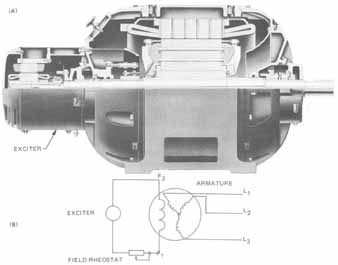
Ill. 4 (A) Self-excited synchronous alternator (Image General Electric Company) (B) Circuit Diagram
FIELD DISCHARGE CIRCUIT
A field discharge switch is used in the excitation circuit of an alternator. This switch eliminates the potential danger to personnel and equipment resulting from the high inductive voltage created when the field circuit's opened.
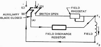
Ill. 5 illustrates the connections for the field circuit of a separately excited alternator. With the discharge switch closed, the field circuit's energized and the field discharge switch functions as a normal double-pole, single-throw switch.
The discharge switch shown in Ill. 6 has an auxiliary switch blade at A in addition to the normal blades at C and D ( Ill. 5).
Ill. 5 Field discharge circuit
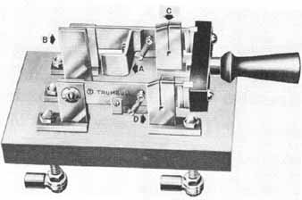
Ill. 6 Field discharge switch
When it's desired to open the field circuit, the following actions must take place.
• Before the main switch contacts open, switch blade A meets contact B and thus pro vides a second path for the current through the field discharge resistor.
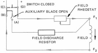
• When the main switch contacts C-D open ( Ill. 7) high inductive voltage is created in the field coils by the collapsing magnetic field.
• This high voltage is dissipated by sending a current through the field discharge resistor.
• This procedure eliminates the possibility of damage to the insulation of the field windings as well as danger to anyone opening the circuit using a standard double pole switch. A field circuit's used with all types of alternators.
Ill. 7 Field discharge circuit
FREQUENCY
The frequency of an alternator is a direct function of (a) the speed of rotation of the armature or the field and (b) the number of poles in the field circuit. The frequency commonly used in the United States is sixty cycles per second or hertz (Hz). Power companies are particularly concerned with maintaining a constant frequency for their energy output since many devices depend on a constant value of frequency. This constant value is achieved by sensitive control of the prime mover speed, driving the alternator.
If the number of field poles in a given alternator is known, then it's possible to deter mine the speed required to produce a desired frequency. One cycle of voltage is generated each time an armature conductor passes across two field poles of opposite magnetic polarity. The frequency in cycles per second or hertz is the number of pairs of poles passed by the conductor in a second. Since the speed of rotating machinery is given in revolutions per minute (r/min), the speed in revolutions per second is obtained by dividing the speed (r/min) by 60. In a two-pole alternator the frequency is:
f = (pairs of poles / 2) ((rev/min)/60)
or:
f = poles x RPM / 120
Where f = frequency in hertz (formerly cycles per second)
p = number of poles
RPM = speed in revolutions per minute
120 = conversion factor
The formula for frequency can be rearranged so that the speed required to give a desired frequency can be obtained.
RPM = 120 x f / P
If a two-pole alternator is to be operated at a frequency of 60 Hz, the correct speed is obtained from the formula RPM = (120 x f)/p
RPM = 120 x 60 / 2 = 3,600 RPM
For a four-pole alternator operated at a frequency of 60 Hz, the required speed is:
f = 120x60/4 = 1800RPM
The two examples given illustrate the previous statement that the frequency of an alternator is a direct function of the speed of rotation and the number of poles in the alternator field circuit.
VOLTAGE CONTROL
The voltage output of an alternator increases as the speed of rotation accelerates, thus increasing the lines of force cut per second. As the field excitation increases, this increases the magnetic fields to the point of magnetic saturation of the field poles.
For practical purposes, an alternator must be operated at a constant speed to maintain a fixed frequency. Thus, the only feasible method of controlling the voltage output is to vary the field excitation.
Field rheostats are used to vary the resistance of the total field circuit. This variation of resistance, in turn, changes the value of field current ( Ill. 4B).
• A low value of field current results in less flux and less induced voltage at a given speed.
• A high field current results in greater field flux and a higher induced voltage at a given speed.
• The value of flux at which the field poles saturate determines the maximum voltage obtainable at a fixed speed and frequency.
ROTATING-FIELD ALTERNATORS
Rotating-field alternators are used extensively because of the ease with which a high-load current can be taken from the machine. The load isn't connected through the use of slip rings or sliding contacts. Thus, the use of rotating-field alternators results in a savings in initial cost and fewer maintenance requirements.
Stator Winding
Ill. 8 illustrates the stator (stationary or nonmoving) windings of a rotating field, three-phase alternator. The three-phase armature windings are embedded 120 degrees from one another in the slots of a laminated steel core which is clamped securely to the alternator frame. Output leads from the stator emerge from the bottom of the stator and connect directly to the load circuit. It can be seen that slip rings and brushes are not required in a stationary winding of this type. As a result, higher values of output voltage and current are possible. Standard values of voltage output for a rotating-field and alternator are as high as 11,000 to 13,800 volts.
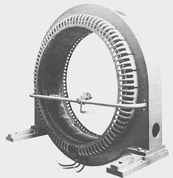
Ill. 8 Stator winding of an alternator (Photo General
Electric Company)
Rotating Field
The rotating portion of a rotating-field alternator consists of field poles mounted on a shaft which is driven by the prime mover. The magnetic flux established by the rotating field poles cuts across the conductors of the stator winding to produce the induced output voltage of the stator.
The following comparison can be made between the rotating-armature alternator and the rotating-field alternator. In the rotating-armature alternator, the armature conductors cut the flux established by stationary field poles. For the rotating-field alternator, the motionless conductors of the stator winding are cut by the flux established by rotating field poles. In each case an induced voltage is generated.
Ill. 9 shows a salient field rotor for low-speed, three-phase alternators. For this type of rotor, the field poles protrude from the rotor support structure which is of steel construction and commonly consists of a hub, spokes, and rim. This support structure is called a spider. Each of the field poles is bolted to the spider. The field poles may be dove- tailed to the spider in some alternators to provide a better support for the poles against the effects of centrifugal force.
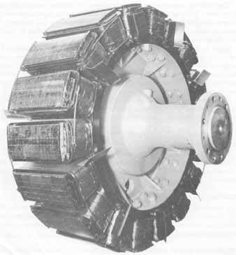
Ill. 9 Alternator rotor, salient field type (Photo General Electric Company)
Ill. 10 shows a non-salient rotor. This type of rotor has a smooth cylindrical surface. The field poles (usually two or four) don't protrude above this smooth surface. Non-salient rotors are used to decrease windage losses on high-speed alternators, and to improve balance and reduce noise.
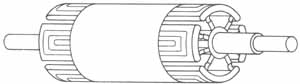
Ill. 10 Alternator rotor, non-salient field type
Power Supply for Rotor
The field windings of both salient and non-salient rotors require dc power. Slip rings and brushes are used to feed the current to the windings at a potential of 100 to 250 volts dc. The brushes and rings are easily maintained because of the low values of field current encountered.
TERMINAL MARKINGS
A standard system of marking leads for field circuits has been established by the ANSI (American National Standards Institute). The field leads for both alternators and generators are indicated by the markings F1 and F2. In addition, the F1 lead always connects to positive bus of the dc source. (See Ills 5 and 7.)
ALTERNATOR REGULATION
Regardless of the type of generator or alternator used in a system, the terminal output voltage of the machine varies with any change in the load current. The impedance of the windings and the power factor of the load Circuit both influence the regulation of an alternator. An increase in load current in a pure resistive load circuit causes a decrease in output voltage. A voltage drop of approximately 10 percent is common when going from a condition of no-load to full-load in a typical alternator.
For an inductive load, an increase in load current will cause a greater voltage drop than is obtained with a pure resistive load. A load with a low value of lagging power factor produces a large drop in output voltage.
A capacitive load circuit produces the opposite effect. In other words, the output voltage rises above the no-load value with an increase in load current and is high at a low value of leading power factor.
AUTOMATIC VOLTAGE CONTROL
Unlike dc generators, alternators cannot be compounded to alter the voltage-load characteristic. Moreover, output voltage variations are more likely to be severe because of changes in the load power factor. As a result, automatic voltage regulators generally are used with alternators.
Automatic voltage regulators change the alternator field current to compensate for any increase or decrease in the load voltage. A relay is used to increase or decrease the field resistance through contactors bridged across a field circuit resistor. As the ac line voltage falls, the relay bypasses sections of the field resistor to cause an increase in the flux and thus increase the induced voltage. An increase in the ac line voltage causes the relay to open contactors across the field resistor to decrease the field current, flux, and induced voltage. Power companies stabilize voltage by using a type of varying ratio transformer as a voltage regulator.
BRUSHLESS EXCITERS WITH SOLID-STATE VOLTAGE CONTROL
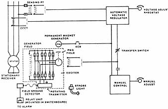
Ill. 11 Diagram of an exciter with permanent magnet generator
(Electric Machinery, Turbodyne Division, Dresser Industries,
Inc.)
The permanent magnet generator ( Ill. 11) supplies high-frequency ac power input to the voltage regulator. Voltage and reactive current feedback information is provided to the regulator from potential and current transformers. Using these feedback signals and a reference point established by setting the voltage adjusting rheostat, the voltage regulator (which has a transfer switch allowing the operator to select automatic regulator control or manual control) provides a controlled dc output. The dc is fed to the field of the rotating exciter; the three-phase, high-frequency ac output is then rectified by a full-wave bridge. This rectified signal is applied to the main generator field. Fully rated, parallel, solid-state diodes with indicating fuses are provided to permit full load generation with a diode (rectifier) out of service. The use of a stroboscope light permits the indicating fuses to be viewed during operation to determine if a diode has failed. Ill. 12 shows a cutaway view of a brushless exciter. Ill. 13 shows the rotating components of a brushless excitation system.
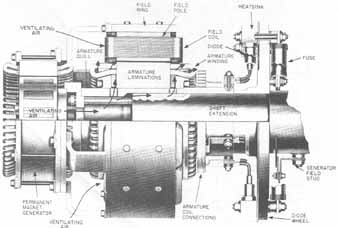
Ill. 12 Cutaway view of a brushless exciter showing the components
(Electric Machinery, Turbodyne Division, Dresser Industries,
Inc.)
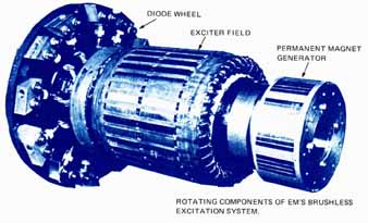
Ill. 13 Rotating components of the brushless excitation system: EXCITER
FIELD; PERMANENT MAGNET GENERATOR; DIODE WHEEL (Electric Machinery,
Turbodyne Division, Dresser Industries, Inc.)
SUMMARY
Three-phase alternators are similar to single-phase alternators in that they can generate electrical power through electromagnetic means. The rotating-field-type alternator is most common in large generating facilities. In electromechanical generation, a magnetic field is turned inside the housing which holds the circuit conductors. The speed of the rotating field will be determined by the desired output frequency. The output voltage of a single generator will be controlled by the strength of the spinning electromagnet. By adjusting the amount of dc supplied to the spinning electromagnetic field, the level of ac output voltage can be controlled. Some generation systems don't connect dc power to the rotor, using brushes and slip rings; instead, they use a system called a brushless exciter which supplies dc to the rotor through electromagnetic induction and rectifiers.
QUIZ
Select the correct answer for each of the following statements.
1. The armature of an alternator ___
a. is the revolving member.
b. is stationary.
c. is the frame.
d. consists of the windings into which the current is induced.
2. In alternators of the revolving-armature type ____
a. slip rings are required in the power output circuit.
b. slip rings are required in the field circuit.
c. slip rings are not required.
d. one slip ring is required.
3. In a protective field discharge circuit, the auxiliary blade of the field switch inserts the discharge resistor ___
a. at the instant the field circuit opens.
b. immediately after the main blade loses contact.
c. immediately before the main blade loses contact.
d. immediately after the main blades make contact.
4. A field discharge circuit resistor ___
a. is installed to stabilize line voltage.
b. is installed to stabilize line current.
c. improves regulation.
d. eliminates danger to people and equipment.
5. The frequency of the alternator output ___
a. is directly proportional to its speed.
b. is inversely proportional to its speed.
c. depends upon its field strength.
d. is inversely proportional to the number of poles.
6. The speed of a six-pole, 60-Hz alternator is:
a. 600 r/min c. 1,800 r/min
b. 1,200 r/min d. 3,600 r/min
7. To deliver power at a frequency of 400 Hz, an eight-pole alternator must be driven at what speed?
a. 600 r/min c. 6,000 r/min
b. 3,600 r/min d. 8,000 r/min
8. High-speed alternators are designed with ___
a. a revolving armature and a nonsalient rotor.
b. a revolving armature and a salient rotor.
c. revolving fields and a salient rotor.
d. revolving fields and a non-salient rotor.
9. Changing the driven speed of an alternator ___
a. changes the voltage magnitude to field saturation.
b. changes the frequency output.
c. does not affect voltage or frequency.
d. both a and b are correct.
10. The magnitude of the voltage output of an alternator is generally controlled by ___
a. the speed of the prime mover.
b. a field rheostat.
c. variable resistance in the output lines.
d. changing the power factor of the load.
11. Alternators use all but one of the following systems to obtain field excitation.
a. a separate dc power supply.
b. a self-excited ac field circuit.
c. a dc exciter on the same shaft as the alternator.
d. a rectifier to convert the output voltage for use in the field circuit.
12. The greatest drop in output voltage results from taking full-load power from an alternator at a ___
a. unity power factor load.
b. high power factor capacitive load.
c. low power factor inductive load.
d. medium power factor capacitive load.
13. Three-phase voltage is ___
a. three polyphase circuits.
b. three distinct voltages.
c. three delta connections.
d. three wye connections.
14. The elementary wiring symbol for a three-phase alternator is__