AMAZON multi-meters discounts AMAZON oscilloscope discounts
OBJECTIVES:
• describe the purposes of engine-driven generating sets.
• list the advantages of using cogenerating sets.
• describe the operation of an automatic transfer switch.
• connect an automatic transfer switch.
• state National Electrical Code requirements.
ENGINE-DRIVEN GENERATING SETS
Diesel, gasoline, or natural gas engine-driven generators are most commonly used to provide another source of emergency or standby power when the normal utility power fails. Turbine power generator sets are also used in this application.
Sturdy, diesel-engine powered generators may lose some of their popularity in the remote, area-sites power systems. The use of hybrid systems using natural energy, such as the wind and the sun, are growing dramatically. So, although diesel generators won't become obsolete for remote site electrical power, a need will exist for a back-up source, as the generator changes its role from a primary energy source to part of a combined source.
Most engine-driven generator sets are rated from a few hundred watts to several hundred kilowatts, although units rated as high as 3,000 kW have been successfully applied. Multiple units, with some working in parallel, are becoming more commonly used to increase generating capacity. Controls may be manual, remote, or automatic, depending upon their application.
Transfer Switches
Switches are required to transfer, or reconnect, the load from a preferred or normal electric power supply to the emergency power supply from the generator set. This is done either manually or automatically. The manual method uses a double-throw switch, operated by hand, to transfer the load from the normal to the emergency power after the standby plant is already running. An automatic transfer switch (ill. 1) usually starts and stops the standby power plant, and transfers the load by relays without requiring the attention of an operator.
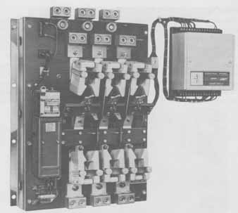
ill. 1 A sophisticated, 600-ampere automatic transfer switch with accessory
group control panel at right. Note the cable terminal Jugs at top and bottom.
(Automatic Switch Co.)
An elementary diagram of a typical automatic transfer switch is shown in ill. 2. (The figure does not include the engine starting controls and other controls.)
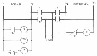
ill. 2 Elementary diagram of an automatic transter switch
When the normal supply on the left side is energized, current flows from L1 through TD (time-delay coil) and back to L2. After a predetermined setting of time delay in closing contact, relay R coil becomes energized. Contact R then closes, and energizes the N coil. Power contacts N then close, supplying the load from the normal or preferred source. When R coil is energized, it also opens the normally closed R contact interlock in the E coil emergency circuit. This safe action insures that each power supply operates independently of the other.
When the normal power fails, all coils on the left, or normal supply side, become de-energized. Relay contact R drops to its normally closed position in the E (emergency coil) circuit. Coil E is then energized, thereby closing the E power contacts feeding the load from an emergency electrical supply.
The time delay action helps to insure that the normal service does not supply the load intermittently with the emergency supply. In other words, the load will wait a preset time until the normal supply is firmly established before it's reconnected to it.
EMERGENCY SYSTEMS
Applicable National Electrical Code (NEC) and local code rules are considered when an on-site generator is selected. These differ, depending on whether the generating set is to function as a power source in a health care facility, such as a hospital, a standby power system, or as an emergency system.
On site generator systems generally are installed wherever great numbers of people gather, and where artificial lighting is required, such as in hotels, theatres, sports arenas, hospitals, and similar institutions. In addition to lighting, emergency systems supply loads which are essential to life and safety. Such installations include fire pumps, ventilation, refrigeration, and signaling systems when essential to maintain life. [ Refer to Article 700 of the National Electrical Code (NEC).]
Standby Power Generation Systems
Standby power generation systems include alternate power systems for applications such as heating, refrigeration, data processing, or communication systems where interruption of normal power would cause human discomfort or damage to the product in manu facture, but where life safety does not depend on the system. (Refer to Article 702 of the NEC.)
UNINTERRUPTIBLE POWER SYSTEMS
Uninterruptible power systems (UPS) are used as power systems to supply critical electronic equipment that includes electronic computer and data processing equipment as described in Article 645 of the National Electrical Code.
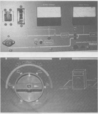
ill. 3 Control panels for uninterruptable power supplies
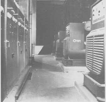
ill. 4 1.8 million watt diesel-driven emergency power generating
system (Photo Onan Corporation, A Subsidiary of McGraw-Edison)
The basic system includes an electronic section that takes the normal line power and converts it to dc power to act as a battery charger. The system has a set of batteries that are constantly being charged. These batteries are also connected to an electronic inverter system to change the dc battery power back to normal ac power to supply an ac load. The concept is to constantly have battery power connected and available to provide a standard level of power to the electronic equipment at all times. The battery system is sized to pro vide the needed volt-amp capacity to the system for a specified period of time. The UPS system also provides protection from low voltage conditions or brown-outs and protection from momentary surges or power delivery failures. These systems can provide continuous, filtered and regulated power to sensitive equipment. The systems themselves can be sized to provide for a few computers or to supply hundreds of computers or other essential equipment. ill. 3 shows the variety of sizes that may be used. If the UPS system is large and requires a bank of batteries to supply the uninterruptible power, the batteries must be installed according to the National Electrical Code.
Health Care Facilities
Health care facilities are governed by several National Electrical Code rules concerning power sources, emergency systems, and essential electrical systems. In particular, refer to NEC Article 517.
ill. 4 shows a diesel-driven emergency power system consisting of four 450-kW electric generating sets. The system is electronically synchronized to deliver 1.8 million watts of emergency power for a hospital. Each unit can also be operated independently of the other units.
LEGALLY REQUIRED STANDBY SYSTEMS
NEC Article 701 states that legally required standby power systems are those systems required by municipal, state, federal, or other codes or a government agency having jurisdiction. In the event of failure of the normal power source, these systems are intended to take over automatically. Legally required standby power systems are installed to serve such loads as communication systems, ventilation and smoke removal systems, sewage disposal, rescue and fire fighting equipment, among others. These are installations that must be installed within the guidelines of the authority having jurisdiction.
COGENERATING PLANTS
Cogeneration is being used to help reduce the cost of purchasing power from a local utility. Many forms of cogeneration are available. Some use the concept of recovering the energy from some manufacturing process to drive electrical generators on site.
Some cogenerating plants are diesel-powered electric generators which are designed to recapture and use the waste heat both from their exhaust and cooling systems (ill. 5).
Although cogenerating plants are not a new concept, they are now being used to combat the energy shortage and the rising prices charged by public utility companies for power generation. About a dozen of the nation’s largest manufacturers of diesel engines have set out to provide competition for the foremost electric utility companies in the United States, As a result, these manufacturers have been concentrating on selling cogenerating plants.
Equipped with cogenerating plants, energy users need no longer rely on public utilities, due to the fact that not only can they make their own electricity, at a lower cost, but provide heating and cooling for their buildings, as well.
Various technical methods have been devised for using cogenerating plants. How ever, all of them capitalize on the fact that the generation of electricity wastes about twice as much energy in the form of heat as that amount of energy which can be generated as electricity. Steam heat, as a waste by-product of manufacturing processes, is now harnessed and used to turn steam turbine electric alternators. This electricity, when not needed, is sold to the public utility which services the plant.
The energy-saving application of cogeneration should result in greater demands for electrical work and , thus, more jobs for electricians. It also should create a particular need for power generator operators having the skills to install, operate, and maintain cogenerating equipment.
SUMMARY
When the normal source of electrical power is interrupted, business and industry may require immediate restoration of power to continue critical operations or life support and safety. There are several methods used to provide power, and different criteria are used to determine which system is required or the best to use. Use the National Electrical Code to determine which system is appropriate to install. In addition to required systems, there is the potential for large power consumers to generate their own power on-site as part of a money-saving feature. This cogeneration is often used to reduce the amount of energy purchased from the utility or to supply the high energy peaks in a facility to save on the demand charges from the utility.
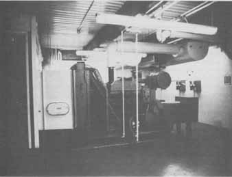
ill. 5 A diesel-powered standby/peak-shaving plant (Photo
Cummins Engine Corp.)
QUIZ:
Select the correct answer for each of the following statements.
1. Engine-driven generating sets are used for:
a. emergency systems.
b. standby power.
c. cogenerating plants.
d. all of these.
2. With an automatic transfer switch, as shown in ill. 1, how does the emergency supply feed the load when power fails?
a. TD energizes R.
b. Normally open contact R opens.
c. Normally closed contact R closes.
d. Power contacts N close.
3, Generating capacities may be increased by using
a. parallel multiple units.
b. series multiple units.
c. turbines.
d. diesels.
4. Cogenerating sets are used
a. to supply emergency power.
b. to supply standby power.
c. to conserve energy.
d. in health care facilities.
5. Electrical capacity is gained with several small generating sets by
a. paralleling machines on the line.
b. reducing the load.
c. placing machines on the line in series.
d. none of these.