AMAZON multi-meters discounts AMAZON oscilloscope discounts
GOALS:
- list the different types of split-phase motors.
- discuss the operation of split-phase motors.
- reverse the direction of rotation of a split-phase motor.
- discuss the operation of multispeed split-phase motors.
- discuss the operation of shaded-pole type motors.
- discuss the operation of repulsion type motors.
- discuss the operation of stepping motors.
- discuss the operation of universal motors.
GLOSSARY OF SINGLE-PHASE MOTOR TERMS
- centrifugal switch--a switch used to disconnect the start windings in a split-phase motor after the motor has accelerated to approximately 75% of rated speed
- compensating winding--a winding used in universal motors to counteract the inductive reactance in the armature windings
- conductive compensation--accomplished by connecting the compensating winding of a universal motor in series with the field winding
- Holtz motor--a type of single phase synchronous motor that operates at a speed of 1200 RPM
- inductive compensation--accomplished by shorting the compensating winding leads together and permitting induced voltage to supply current to the winding
- multispeed single-phase motors--motors designed to operate at more than one full load speed
- neutral plane--the point at which no voltage is induced in the armature winding
- run winding--one of the windings in a split-phase motor
- shaded-pole induction motor--a single-phase motor that produces a rotating magnetic field by shading one side of each pole piece; shading is accomplished by placing a loop of large copper wire around one side of the pole piece shading coil the loop of large wire used to form a shaded pole
- split-phase motor--a type of single-phase motor that splits the current flow through two separate windings to produce a rotating magnetic field
- start winding one of the windings used in a split-phase motor
- synchronous motors--motors that operate at a constant speed from no load to full load synchronous speed the speed of the rotating magnetic field of an AC induction motor
- two phase--a power system that produces two separate phase voltages 90° apart universal motor a type of single-phase motor that can operate on either direct or alternating current
- Warren motor--a type of single phase synchronous motor that operates at a speed of 3600 RPM
Although most of the large motors used in industry are three-phase, at times single-phase motors must be used. Single-phase motors are used almost exclusively to operate home appliances such as air conditioners, refrigerators, well pumps, and fans. They are generally designed to operate on 120 V or 240 V. They range in size from fractional horsepower to several horsepower, depending on the application.
SPLIT-PHASE MOTORS
Split-phase motors fall into three general classifications:
- The resistance-start induction-run motor.
- The capacitor-start induction-run motor.
- The capacitor-start capacitor-run motor.
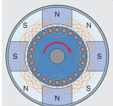
Although these motors have different operating characteristics, they are similar in construction and use the same operating principle. Split-phase motors receive their name from the way they operate on the principle of a rotating magnetic field. A rotating magnetic field, however, cannot be produced with only one phase. Split-phase motors, therefore, split the cur rent flow through two separate windings to simulate a two-phase power system. A rotating magnetic field can be produced with a two-phase system.
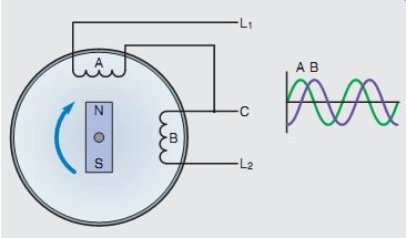
FGR. 1 A two-phase alternator produces voltages that are 90° out of phase
with each other.
THE TWO-PHASE SYSTEM
In some parts of the world, two-phase power is produced. A two-phase system is produced by having an alternator with two sets of coils wound 90° apart (FGR. 1). The voltages of a two-phase sys tem are, therefore, 90° out of phase with each other. These two out-of-phase voltages can pro duce a rotating magnetic field. Because there have to be two voltages or currents out of phase with each other to produce a rotating magnetic field, split-phase motors use two separate windings to create a phase difference between the currents in the two windings. These motors literally split one phase and produce a second phase, hence the name split-phase motor.
==
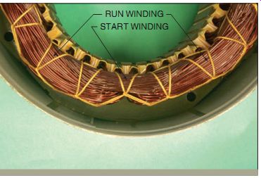
FGR. 2A Stator winding used with resistant start induction-run motors.
==
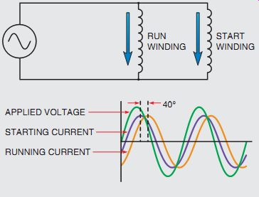
The stator of a split-phase motor contains two separate windings, the start winding and the run winding.
The start winding is made of small wire and is placed near the top of the stator core. The run winding is made of relatively large wire and is placed in the bottom of the stator core. Fgrs. -2A and 2B show photographs of two split-phase stators. The stator in A is used for a resistance-start induction-run motor, or a capacitor-start, induction-run motor.
The stator in B is used for a capacitor-start, capacitor-run motor. Both stators contain four poles, and the start winding is placed at a 90° angle from the run winding.
Notice the difference in size and position of the two windings of the stator shown in FGR. 2A.
The start winding is made from small wire and placed near the top of the stator core. This causes it to have a higher resistance than the run winding.
The start winding is located between the poles of the run winding. The run winding is made with larger wire and placed near the bottom of the core. This gives it higher inductive reactance and less resistance than the start winding. These two windings are connected in parallel with each other (FGR. 3).
When power is applied to the stator, current flows through both windings. Because the start winding is more resistive, the current flow through it will be more in phase with the applied voltage than will the current flow through the run winding.
The current flow through the run winding will lag the applied voltage due to inductive reactance.
These two out-of-phase currents create a rotating magnetic field in the stator. The speed of this rotating magnetic field is called synchronous speed and is determined by two factors:
- number of stator poles
- frequency of the applied voltage.
The speed of the rotating magnetic field can be determined using the formula:
S = 120 F/P
Where:
S = RPM
F = Frequency in hertz
P = Number of stator poles
EXAMPLE
A single-phase motor contains six stator poles and is connected to a 60-Hz line. What is the speed of the rotating magnetic field?
S = 120 _ 60 6
S = 1200 RPM
The power line frequency throughout the United States is 60 Hertz. Table 19-1 lists the revolutions per minute (RPM) for motors with different numbers of stator poles.
===
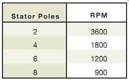
Tbl. 1 RPM at 60 Hz
Stator Poles -- RPM
- 2 -- 3600
- 4 -- 1800
- 6 -- 1200
- 8 -- 900
===
==
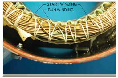
FGR. 2B Stator winding used with capacitor start capacitor-run motors.
==
FGR. 3 The start and run windings are connected in parallel with each
other.
==
RESISTANCE-START INDUCTION-RUN MOTORS
The resistance-start induction-run motor is so named because the out-of-phase condition between start and run winding current is caused by the start winding being more resistive than the run winding.
The amount of starting torque produced by a split phase motor is determined by three factors:
1. The strength of the magnetic field of the stator.
2. The strength of the magnetic field of the rotor.
3. The phase angle difference between current in the start winding and current in the run winding. (Maximum torque is produced when these two currents are 90° out of phase with each other.)
Although these two currents are out of phase with each other, they are not 90° out of phase. The run winding is more inductive than the start winding, but it does have some resistance, which pre vents the current from being 90° out of phase with the voltage. The start winding is more resistive than the run winding, but it does have some inductive reactance, preventing the current from being in phase with the applied voltage. Therefore, a phase angle difference of 35° to 40° is produced between these two currents, resulting in a rather poor starting torque (FGR. 4).
===
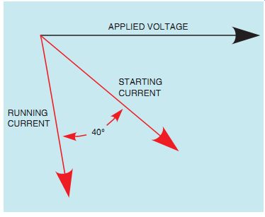
FGR. 4 Running current and starting current are 35° to 40° out of phase
with each other.
===
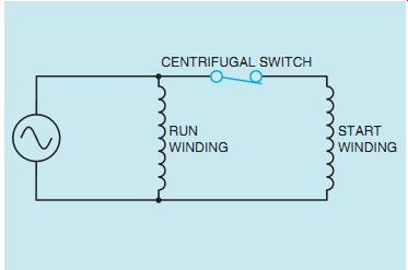
FGR. 5 A centrifugal switch is used to disconnect the start winding from
the circuit.
===
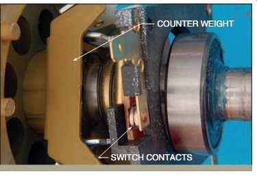
FGR. 6 The centrifugal switch is closed when the rotor is not turning.
===
DISCONNECTING THE START WINDING
A stator rotating magnetic field is necessary only to start the rotor turning. Once the rotor has accelerated to approximately 75% of rated speed, the start winding can be disconnected from the circuit and the motor will continue to operate with only the run winding energized. Motors that are not hermetically sealed (most refrigeration and air conditioning compressors are hermetically sealed) use a centrifugal switch to disconnect the start windings from the circuit. The contacts of the centrifugal switch are connected in series with the start winding (FGR. 5). The centrifugal switch contains a set of spring-loaded weights. When the shaft is not turning, the springs hold a fiber washer in contact with the movable contact of the switch (FGR. 6). The fiber washer causes the movable contact to complete a circuit with a stationary contact.
When the rotor accelerates to about 75% of rated speed, centrifugal force causes the weights to overcome the force of the springs. The fiber washer retracts and permits the contacts to open and disconnect the start winding from the circuit (FGR. 7). The start winding of this type motor is intended to be energized only during the period of time that the motor is actually starting. If the start winding is not disconnected, it will be dam aged by excessive current flow.
==
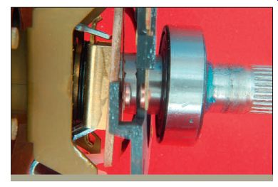
FGR. 7 The contact opens when the rotor reaches about 75% of rated speed.
==
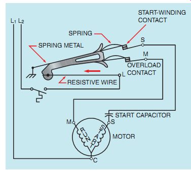
FGR. 8 Hot-wire relay connection.
==
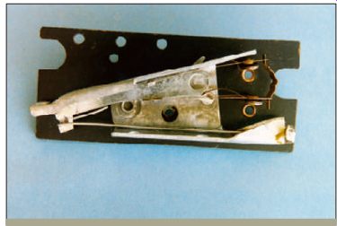
FGR. 9 Hot-wire type of starting relay.
==
STARTING RELAYS
Resistance-start induction-run and capacitor-start induction-run motors are sometimes hermetically sealed, such as with air conditioning and refrigeration compressors. When they are hermetically sealed, a centrifugal switch cannot be used to disconnect the start winding. A device that can be mounted externally is needed to disconnect the start windings from the circuit. Starting relays per form this function.
There are three basic types of starting relays used with the resistance-start and capacitor-start motors:
1 Hot-wire relay.
2 Current relay.
3 Solid state starting relay.
The hot-wire relay functions as both a starting relay and an overload relay. In the circuit shown in FGR. 8, it is assumed that a thermostat controls the operation of the motor. When the thermostat closes, current flows through a resistive wire and through two normally closed contacts connected to the start and run windings of the motor. The high starting current of the motor rapidly heats the resistive wire, causing it to expand. The expansion of the wire causes the spring-loaded start winding contact to open and disconnect the start winding from the circuit, reducing motor current. If the motor is not over loaded, the resistive wire never becomes hot enough to cause the overload contact to open, and the motor continues to run. If the motor becomes overloaded, however, the resistive wire expands enough to open the overload contact and disconnect the motor from the line. A photograph of a hot-wire starting relay is shown in FGR. 9.
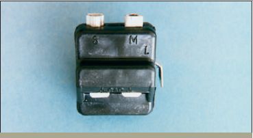
The current relay also operates by sensing the amount of current flow in the circuit. This type of relay operates on the principle of a magnetic field instead of expanding metal. The current relay contains a coil with a few turns of large wire and a set of normally open contacts, FGR. 10. The coil of the relay is connected in series with the run winding of the motor, and the contacts are connected in series with the start winding, as shown in FGR. 11. When the thermostat contact closes, power is applied to the run winding of the motor. Because the start winding is open, the motor cannot start, causing a high current to flow in the run winding circuit. This high current flow produces a strong magnetic field in the coil of the relay, causing the normally open contacts to close and connect the start winding to the circuit.
When the motor starts, the run-winding current is greatly reduced, permitting the start contacts to reopen and disconnect the start winding from the circuit.
===
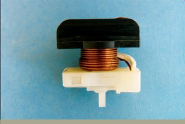
FGR. 10 Current type of starting relay.
===
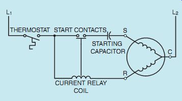
FGR. 11 Current relay connection.
===
FGR. 12 Solid state starting relay.
===
FGR. 13 Solid state starting relay connection.
===
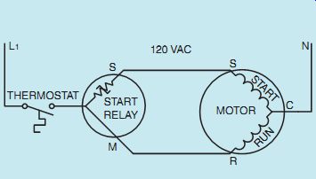
The solid state starting relay, FGR. 12, per forms the same basic function as the current relay and in many cases is replacing both the current relay and the centrifugal switch. The solid state starting relay is generally more reliable and less expensive than the current relay or the centrifugal switch. The solid state starting relay is actually an electronic component known as a thermistor. A thermistor is a device that exhibits a change of resistance with a change of temperature. This particular thermistor has a positive coefficient of temperature, which means that when its temperature increases, its resistance increases also. The schematic diagram in FGR. 13 illustrates the connection of the solid state starting relay. The thermistor is connected in series with the start winding of the motor. When the motor is not in operation, the thermistor is at a low temperature and its resistance is low, typically 3 or 4 ohms.
When the thermostat contact closes, current flows to both the run and start windings of the motor. The current flowing through the thermistor causes an increase in temperature. This increased temperature causes the resistance of the thermistor to suddenly change to a high value of several thou sand ohms. The change of temperature is so sudden that it has the effect of opening a set of contacts.
Although the start winding is never completely disconnected from the power line, the amount of cur rent flow through it is very small, typically 0.03 to 0.05 amperes, and does not affect the operation of the motor. This small amount of leakage current maintains the temperature of the thermistor and pre vents it from returning to a low value of resistance.
After the motor is disconnected from the power line, a cooldown time of 2 to 3 minutes should be allowed to permit the thermistor to return to a low resistance before the motor is restarted.
RELATIONSHIP OF STATOR AND ROTOR FIELDS
The split-phase motor contains a squirrel-cage rotor, (FGR. 14). When power is connected to the stator windings, the rotating magnetic field induces a voltage into the bars of the squirrel cage rotor. The induced voltage causes current to flow in the rotor, and a magnetic field is produced around the rotor bars. The magnetic field of the rotor is attracted to the stator field, and the rotor begins to turn in the direction of the rotating magnetic field. After the centrifugal switch opens, only the run winding induces voltage into the rotor. This induced voltage is in phase with the stator current.
The inductive reactance of the rotor is high, causing the rotor current to be almost 90° out of phase with the induced voltage. This causes the pulsating magnetic field of the rotor to lag the pulsating magnetic field of the stator by 90°. Magnetic poles, located midway between the stator poles, are created in the rotor (FGR. 15). These two pulsating magnetic fields produce a rotating magnetic field of their own, and the rotor continues to rotate.
===
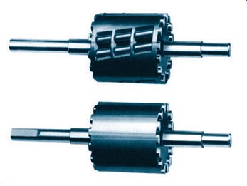
FGR. 14 Squirrel-cage rotor used in a split phase motor.
===
FGR. 15 A rotating magnetic field is produced by the stator and rotor
flux.
===
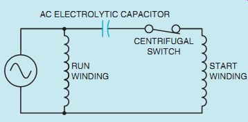
FGR. 16 An AC electrolytic capacitor is connected in series with the start
winding.
===
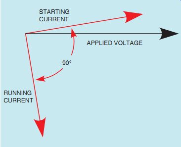
FGR. 17 Run winding current and start winding current are 90° out of phase
with each other.
===
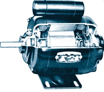
FGR. 18 Capacitor-start induction-run motor.
===
DIRECTION OF ROTATION
The direction of rotation for the motor is determined by the direction of rotation of the rotating magnetic field created by the run and start windings when the motor is first started. The direction of motor rotation can be changed by reversing the connection of either the start winding or the run winding, but not both. If the start winding is disconnected, the motor can be operated in either direction by manually turning the rotor shaft in the desired direction of rotation.
CAPACITOR-START INDUCTION-RUN MOTORS
The capacitor-start induction-run motor is very similar in construction and operation to the resistance-start induction-run motor. The capacitor start induction-run motor, however, has an AC electrolytic capacitor connected in series with the centrifugal switch and start winding (FGR. 16).
Although the running characteristics of the capacitor-start induction-run motor and the resistance-start induction-run motor are identical, the starting characteristics are not. The capacitor start induction-run motor produces a starting torque that is substantially higher than that of the resistance-start induction-run motor. Recall that one of the factors that determines the starting torque for a split-phase motor is the phase angle difference between start winding current and run winding current. The starting torque of a resistance-start induction-run motor is low because the phase angle difference between these two cur rents is only about 40° (FGR. 16).
When a capacitor of the proper size is connected in series with the start winding, it causes the start winding current to lead the applied volt age. This leading current produces a 90° phase shift between run winding current and start winding current (FGR. 17). Maximum starting torque is developed at this point.
Although the capacitor-start induction-run motor has a high starting torque, the motor should not be started more than about eight times per hour.
Frequent starting can damage the start capacitor due to overheating. If the capacitor must be replaced, care should be taken to use a capacitor of the correct microfarad rating. If a capacitor with too little capacitance is used, the starting current will be less than 90° out of phase with the running current, and the starting torque will be reduced. If the capacitance value is too great, the starting current will be more than 90° out of phase with the running current, and the starting torque will again be reduced. A capacitor-start induction-run motor is shown in FGR. 18.
DUAL-VOLTAGE SPLIT-PHASE MOTORS
==
FGR. 19 Dual-voltage windings for a split phase motor.
==
FGR. 20 High-voltage connection for a split phase motor with two run
and two start windings. START WINDINGS
==
FGR. 21 Low-voltage connection for a split phase motor with two run and
two start windings.
==
FGR. 22 Dual-voltage motor with one start winding labeled T5 and T6.
==
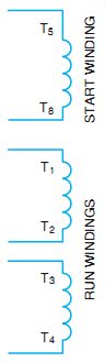
FGR. 23 Dual-voltage motor with one start winding labeled T5 and T8.
==
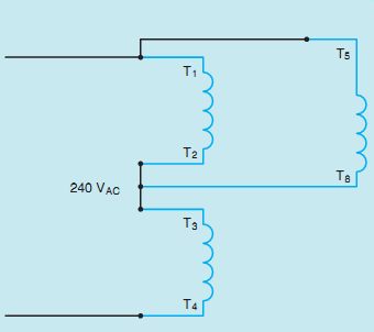
FGR. 24 High-voltage connection with one start winding.
==
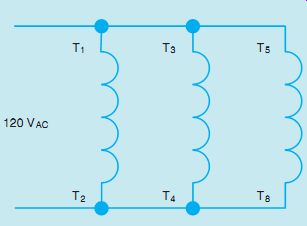
FGR. 25 Low-voltage connection for a split phase motor with one start
winding.
==
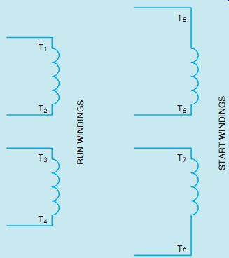
Many split-phase motors are designed for operation on 120 or 240 V. FGR. 19 shows the schematic diagram of a split-phase motor designed for dual-voltage operation. This particular motor contains two run windings and two start windings.
The lead numbers for single-phase motors are numbered in a standard manner. One of the run windings has lead numbers of T1 and T2. The other run winding has its leads numbered T3 and T4. This motor uses two different sets of start winding leads. One set is labeled T5 and T6, and the other set is labeled T7 and T8.
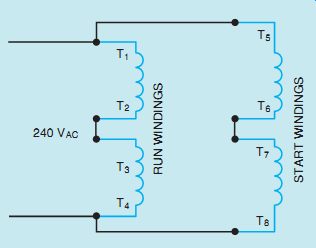
If the motor is to be connected for high-voltage operation, the run windings and start windings will be connected in series as shown in FGR. 20.
The start windings are then connected in parallel with the run windings. If the opposite direction of rotation is desired, T5 and T8 will be changed.
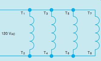
For low-voltage operation, the windings must be connected in parallel as shown in FGR. 21.
This connection is made by first connecting the run windings in parallel by hooking T1 and T3 together and T2 and T4 together. The start windings are paralleled by connecting T5 and T7 together and T6 and T8 together. The start windings are then connected in parallel with the run windings. If the opposite direction of rotation is desired, T5 and T6 should be reversed along with T7 and T8.
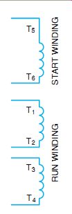
Not all dual-voltage single-phase motors contain two sets of start windings. FGR. 22 shows the schematic diagram of a motor that contains two sets of run windings and only one start winding.
In this illustration, the start winding is labeled T5 and T6. Some motors, however, identify the start winding by labeling it T5 and T8 as shown in FGR. 23.
Regardless of which method is used to label the terminal leads of the start winding, the connection will be the same. If the motor is to be connected for high-voltage operation, the run windings will be connected in series and the start winding will be connected in parallel with one of the run windings, as shown in FGR. 24. In this type of motor, each winding is rated at 120 V. If the run windings are connected in series across 240 V, each winding will have a voltage drop of 120 V. By connecting the start winding in parallel across only one run winding, it will receive only 120 V when power is applied to the motor. If the opposite direction of rotation is desired, T5 and T8 should be changed.
If the motor is to be operated on low voltage, the windings are connected in parallel as shown in FGR. 25. Since all windings are connected in parallel, each will receive 120 V when power is applied to the motor.