AMAZON multi-meters discounts AMAZON oscilloscope discounts
OBJECTIVES:
• discuss the relationship of voltage and current in circuits that contain resistance, inductance, and capacitance.
• compute circuit values for RLC series circuits.
• compute circuit values for RLC parallel circuits.
• connect an RLC series circuit and measure circuit values with electrical instruments.
• connect an RLC parallel circuit and measure circuit values with electrical instruments.
RESISTIVE-INDUCTIVE-CAPACITIVE CIRCUIT TERMS:
- current flow through the capacitor (IC)--the amount of current flowing through the capacitor
- current flow through the resistor (IR)--the amount of current flowing through the resistor
-------------------------------
This Section discusses circuits that contain resistance, inductance, and capacitance. Mathematical calculations will be used to illustrate the relation ship of voltage and current in both series and parallel circuits. It will be seen that values of voltage in an RLC series circuit can be higher across a particular component than the voltage applied to the circuit. In parallel circuits, the current through a single branch can be greater than the total current applied to the circuit. This is because inductive and capacitive values cancel each other, but both are still very real values.
RLC SERIES CIRCUITS
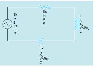
When an alternating-current circuit contains elements of resistance, inductance, and capacitance connected in series, the current will be the same through all components, but the voltages that are dropped across each element will be out of phase with each other. The voltage dropped across the resistance will be in phase with the current, the voltage dropped across the inductor will lead the current by 90°, and the voltage dropped across the capacitor will lag the current by 90° (FIG. 1). An RLC series circuit is shown in FIG. 2. The ratio of resistance, inductance, and capacitance will determine how much the applied voltage will lead or lag the circuit current.
If the circuit contains more inductance VARs than capacitive VARs, the current will lag the applied voltage and the power factor will be a lagging power factor. If there are more capacitive VARs than inductive VARs, the current will lead the voltage and the power factor will be a leading power factor.
Since inductive reactance and capacitive reactance are 180° out of phase with each other, they cancel each other in an AC circuit. This can permit the impedance of the circuit to become less than either or both of the reactances, producing a high amount of current flow through the circuit.
When Ohm's law is applied to the circuit values, it will be seen that the voltage drops developed across these components can be higher than the applied voltage.
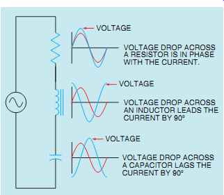
FIG. 1 The current and voltage relationships in an RLC series circuit.
EXAMPLE: CIRCUIT 1
It is assumed that the circuit shown in FIG. 2 has an applied voltage of 240 volts at 60 Hz and the resistor has a value of 12 Ohm, the inductor has an inductive reactance of 24 Ohm, and the capacitor has a capacitive reactance of 8 Ohm. The following unknown values will be found:
Z - Impedance of the circuit
I - Circuit current
ER - Voltage drop across the resistor
P - True power (watts)
L - Inductance of the inductor
EL - Voltage drop across the inductor
VARsL - Reactive power of the inductor
C - Capacitance of the capacitor
EC - Voltage drop across the capacitor
VARsC - Reactive power of the capacitor
VA - Volt-amps (apparent power)
PF - Power factor
θu - Angle theta
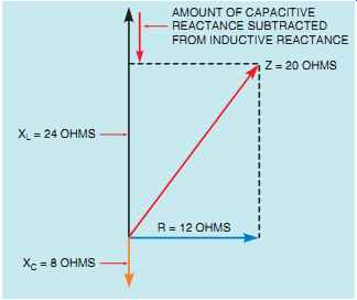
FIG. 3 Inductive and capacitive values subtract from each other.
COMPUTING IMPEDANCE
The impedance of the circuit is the sum of resistance, inductive reactance, and capacitive reactance. Since inductive reactance and capacitive reactance are 180° out of phase with each other, vector addition must be used to find their sum.
This results in the smaller of the two reactive values being subtracted from the larger (FIG. 3). When this is done, the smaller value is eliminated and the larger value is reduced by the amount of the smaller value. The total impedance will be the hypotenuse formed by the resulting right triangle. The impedance will be computed by using the formula:

In the above formula, the capacitive reactance is subtracted from the inductive reactance, and then the difference is squared. If the capacitive reactance should be a larger value than inductive reactance, the difference will be a negative number. This will have no effect on the answer, however, because the square of a negative or positive number will always be positive.
TOTAL CIRCUIT CURRENT
The total current flow through the circuit can now be computed using the formula:
I = ET Z I = 240 20
I = 12 Amps
In a series circuit, the current flow is the same at any point in the circuit. Therefore, 12 amps will flow through each of the circuit components.
RESISTIVE VOLTAGE DROP (ER)
The voltage drop across the resistor can be computed using the formula:
ER = I x R
ER = 12 x 12
ER = 144 volts
TRUE POWER ( WATTS)
The true power of the circuit can be computed using any of the pure resistive values. In this example, true power will be found using the formula:
P = ER x I
P = 144 x 12
P = 1728 watts
INDUCTANCE (L)
The amount of inductance in the circuit can be computed using the formula:
L = XL 2pF
L = 24 377
L = 0.0637 Henry
VOLTAGE DROP ACROSS THE INDUCTOR (EL)
The amount of voltage drop across the inductor can be computed using the formula:
EL = I x XL
EL = 12 x 24
EL = 288 volts
Notice that the voltage drop across the inductor is greater than the applied voltage.
INDUCTIVE VARs (VARsL)
The amount of reactive power of the inductor can be computed by using inductive values.
VARsL = EL x I
VARsL = 288 x 12
VARsL = 3456
CAPACITANCE (C)
The amount of capacitance in the circuit can be computed by using the formula:
C = 1 2pFXC C = 1 377 x 8
C = 0.00033156 F or 331.56 µF
VOLTAGE DROP ACROSS THE CAPACITOR (EC)
The voltage dropped across the capacitor can be computed using the formula:
EC = I x XC EC = 12 x 8 EC = 96 volts
CAPACITIVE VARs (VARsC)
The amount of capacitive VARs can be computed using the formula:
VARsC = EC x I VARsC = 96 x 12 VARsC = 1152
APPARENT POWER (VA)
The volt-amps (apparent power) can be computed by multiplying the applied voltage and the circuit current.
VA = ET x I
VA = 240 x 12
VA = 2880
The apparent power can also be found by vector addition of true power, inductive VARs, and capacitive VARs. As with the addition of resistance, inductive reactance, and capacitive reactance, inductive VARs, VARsL, and capacitive VARs, VARsC, are 180° out of phase with each other. This will result in the elimination of the smaller and a reduction of the larger. The following formula can be used to determine apparent power:

POWER FACTOR (PF)
The power factor can be computed by dividing the true power of the circuit by the apparent power.
The answer is then multiplied by 100 to change the decimal into a percent.
PF = P VA x 100
PF = 1728 2880
_ 100 PF = 0:6 x 100 or 60%
ANGLE THETA (θu)
The power factor is the cosine of angle theta.
COS PF =θu COS 0:6 = 53:13°
The circuit, with all computed values, is shown in FIG. 4.
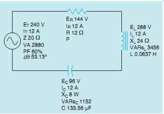
FIG. 4 RLC series circuit with all computed values.
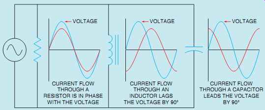
FIG. 5 The voltage is the same across any branch of a parallel circuit.
RLC PARALLEL CIRCUITS
When an alternating-current circuit contains elements of resistance, inductance, and capacitance connected in parallel, the voltage dropped across each element will be the same. The current flowing through each branch, however, will be out of phase with each other (FIG. 5). The current flowing through a pure resistive element will be in phase with the applied voltage. The current flowing through a pure inductive element lags the applied voltage by 90 electrical degrees, and the current flowing through a pure capacitive element will lead the voltage by 90 electrical degrees. The phase angle difference between the applied voltage and the total current is determined by the ratio of resistance, inductance, and capacitance connected in parallel. As with RLC series circuits, if the inductive VARs are greater than the capacitive VARs, the current will lag the voltage and the power factor will be lagging. If the capacitive VARs are greater, the current will lead the voltage and the power factor will be leading.
EXAMPLE CIRCUIT 2
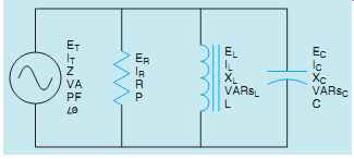
FIG. 6 An RLC parallel circuit.
An RLC parallel circuit is shown in FIG. 6.
It is assumed that the circuit is connected to a 240-volt 60-Hz line. The resistor has a resistance of 12 Ohm, the inductor has an inductive reactance of 8 Ohm, and the capacitor has a capacitive reactance of 16 Ohm. The following unknown values will be computed:
Z - Impedance of the circuit
IT - Total circuit current
IR - Current flow through the resistor
P - True power (watts)
L - Inductance of the inductor
IL - Current flow through the inductor
VARsL - Reactive power of the inductor
C - Capacitance
IC - Current flow through the capacitor
VARsC - Reactive power of the capacitor
VA - Volt-amps (apparent power)
PF - Power factor
θu - Angle theta
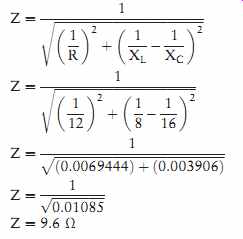
COMPUTING THE IMPEDANCE
The impedance of the circuit is the reciprocal of the sum of the reciprocals of each leg. Since these values are out of phase with each other, vector addition must be used.
RESISTIVE CURRENT (IR)
The first unknown value to be found will be the current flow through the resistor (IR). This can be computed by using the formula:
IR = E R
IR = 240 12
IR = 20 Amps
TRUE POWER (WATTS)
The true power, or watts, can be computed using the formula:
P = E x IR
P = 240 x 20
P = 4800 watts
INDUCTIVE CURRENT (IL)
The amount of current flow through the inductor can be computed using the formula:
IL = E XL
IL = 240/8
IL = 30 Amps
INDUCTIVE VARs (VARsL)
The amount of reactive power or VARs produced by the inductor can be computed using the formula:
VARsL = E x IL
VARsL = 240 x 30
VARsL = 7200
INDUCTANCE (L)
The amount of inductance in the circuit can be computed using the formula:
L = XL 2pF
L = 8 377
L = 0.021 Henry
CAPACITIVE CURRENT (IC)
The current flow through the capacitor (IC) can be computed using the formula:
IC = E XC
IC = 240 16
IC = 15 Amps
CAPACITANCE (C)
The amount of circuit capacitance can be computed using the formula:
C = 1 2pFXC C = 1 377 x 16 C = 0:00016578 F or 165:78 µF
CAPACITIVE VARs (VARsC)
The capacitive VARs can be computed using the formula:
VARsC = E x IC
VARsC = 240 x 15
VARsC = 2400
TOTAL CURRENT (IT)
The amount of total current flow in the circuit can be computed by vector addition of the currents flowing through each leg of the circuit (FIG. 7). The inductive current is 180° out of phase with the capacitive current. These two currents will tend to cancel each other, resulting in the elimination of the smaller and the reduction of the larger. The total circuit is the hypotenuse of the resulting right triangle (FIG. 8). The formula shown below can be used to find total circuit current.
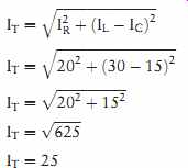
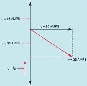
FIG. 7 Relationship of currents in an RLC parallel circuit.
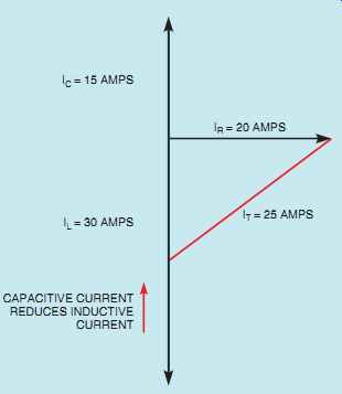
FIG. 8 The total current is the hypotenuse of a right triangle formed
by the resistive current, capacitive current, and inductive current.
The total current could also be computed by using the value of impedance found earlier in the problem.
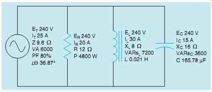
FIG. 9 RLC parallel circuit with all values.
IT = E Z
IT = 240 9.6
IT = 25 Amps
APPARENT POWER (VA)
Now that the total circuit current has been computed, the apparent power or volt-amps can be found using the formula:
VA = E x IT
VA = 240 x 25
VA = 6000
The apparent power can also be found by vector addition of the true power and reactive power:

POWER FACTOR (PF)
The power factor can now be computed using the formula:
PF = P VA x 100
PF = 4800 6000
_ 100 PF = 0.80 x 100 or 80%
ANGLE THETA (θu)
The power factor is the cosine of angle theta.
Therefore, angle theta is:
COSθu = PF
COSθu = 0.80
θu = 36:87
The circuit, with all completed values, is shown in FIG. 9.
SUMMARY
RLC SERIES CIRCUITS
• The voltage drop across the resistive part of an RLC series circuit will be in phase with the current.
• The voltage drop across the inductive part of an RLC series circuit will lead the current by 90°.
• The voltage drop across the capacitive part of an RLC series circuit will lag the current by 90°.
• Vector addition can be used in an RLC series circuit to find values of total voltage, impedance, and apparent power.
• In an RLC circuit, inductive and capacitive values are 180° out of phase with each other.
Adding them results in the elimination of the smaller value and reduction of the larger value.
RLC PARALLEL CIRCUITS
• The voltage is the same across all branches of a parallel circuit.
• The current flow in the resistive branch of an RLC parallel circuit will be in phase with the voltage.
• The current flow in the inductive branch of an RLC parallel circuit will lag the voltage by 90°.
• The current flow in the capacitive branch of an RLC parallel circuit will lead the voltage by 90°.
• Angle theta is determined by the ratio of resistance, inductance, and capacitance.
