AMAZON multi-meters discounts AMAZON oscilloscope discounts
OBJECTIVES:
• discuss the relationship of voltage and current in circuits that contain both resistance and capacitance.
• compute circuit values for R-C series circuits.
• compute circuit values for R-C parallel circuits.
• connect an R-C series circuit and measure circuit values with electrical instruments.
• connect an R-C parallel circuit and measure circuit values with electrical instruments.
RESISTIVE-CAPACITIVE CIRCUIT TERMS:
- voltage drop across the capacitor (EC)--the amount of voltage drop across the capacitor
- voltage drop across the resistor (ER)--the amount of voltage drop across the resistor
--------------------
This Section discusses circuits that contain both resistance and capacitance. Mathematical calculations will be used to illustrate the relationship of voltage and current in both series and parallel circuits.
Circuits that contain both resistance and capacitance are very similar to the circuits that contain resistance and inductance that were discussed in previous Sections. The primary difference between them is the relationship of voltage and current in the circuit. A pure inductive circuit causes current to lag the applied voltage by 90°.
A pure capacitive circuit causes the current to lead the applied voltage by 90°. In a circuit that contains both resistance and inductance, the current will lag the voltage by some amount between 0° and 90°, depending on the ratio of resistance and inductance. Resistive-inductive circuits produce a lagging power factor. Circuits that contain both resistance and capacitance will cause the current to lead the voltage by some amount between 0° and 90°, depending on the ratio of resistance and capacitance. Resistive-capacitive circuits pro duce a leading power factor. The mathematical formulas used to determine values in a resistive capacitive circuit are very similar to those used in a resistive-inductive circuit.
R-C SERIES CIRCUITS
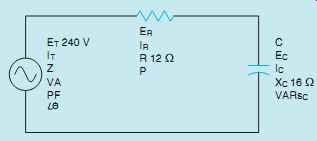
The circuit shown in FIG. 1 contains a resistor and a capacitor connected in series with each other.
The resistor has a resistance of 12 ohms and the capacitor has a capacitive reactance of 16 ohms.
A voltage of 240 V at 60 Hz is connected to the circuit. The following unknown values will be determined:
Z - Total circuit impedance
I - Circuit current
ER - Voltage drop across the resistor
P - Watts (true power)
C - Capacitance of the capacitor
EC - Voltage drop across the capacitor
VARsC - Reactive power
VA - Apparent power
PF - Power factor
θu - Angle theta (phase angle difference between the voltage and current)
IMPEDANCE
Impedance is the total current-limiting effect in the circuit. It is a combination of resistance and capacitive reactance. Since these two elements are connected in series, their ohmic values must be added.
However, these two current-limiting elements are 90° out of phase with each other, which means that vector addition must be used. Impedance can be determined using the formula:

TOTAL CURRENT
Now that the circuit impedance has been determined, the circuit current can be calculated using the formula:
I = ET/Z
I = 240/20
I = 12 Amps
VOLTAGE DROP ACROSS THE RESISTOR
In any series circuit, the current is the same in all parts of the circuit. In this circuit, 12 amperes of current flows through both the resistor and capacitor. The voltage drop across the resistor (ER) can be computed using the formula:
ER = I x R
ER = 12 x 12
ER = 144 Volts
TRUE POWER
The true power (P) can be determined using any of the formulas for determining watts, provided that values that apply to only resistive parts of the circuit are used. The only time that true power, or watts, is produced is when both voltage and current are in phase with each other. This occurs only in the resistive elements of the circuit. The true power in this circuit will be determined using the formula:
P = I^2 _ R
P = 12 A x 12 A x 12 Ohm
P = 1728 Watts
CAPACITANCE
The value of the capacitor can be determined using the formula:
C = 1 2pF
XC C = 1 377 x 16
C = 0:0001658 F or 165:8 µF
VOLTAGE DROP ACROSS THE CAPACITOR
The voltage drop across the capacitor (EC) can be determined using values that apply to the capacitor. The formula used to determine voltage drop across the capacitor will be:
EC = I x XC EC = 12 x 16 EC = 192 Volts
TOTAL VOLTAGE
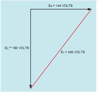
Although the total voltage applied to this circuit is given as 240 volts, it is possible to compute the total voltage by adding the voltage drops across the different elements in the circuit. One of the rules concerning series circuits is that the applied voltage is equal to the sum of the voltage drops in the circuit. In a circuit of this type, how ever, the vector addition must be employed because the voltage across the resistive element is in phase with the current and the voltage across the capacitive element lags the current by 90° (FIG. 2). The total voltage can be determined using the formula:


FIG. 2 The total voltage is the vector sum of the voltage across
the resistor and the voltage across the capacitor.
REACTIVE POWER
The reactive power (VARs) can be determined using the values that apply to the reactive circuit components. The formulas for determining VARs are very similar to those used to determine watts, except that reactive values of voltage, current, and reactance are used. In this example, the formula for determining the reactive power will be:
VARsC = EC x I
VARsC = 192 x 12
VARsC = 2304
APPARENT POWER
The apparent power is generally referred to as the volt-amps. It can be computed using formulas similar to those for determining watts and VARs, except that total circuit values are used. In this circuit, the apparent power will be determined using the formula:
VA = E^2 T/Z
VA = 240^2/20
VA = 2880
POWER
The power factor is the ratio of the true power, or watts, as compared to the apparent power, or volt amps. In this circuit, the current leads the applied voltage, producing a leading power factor. The power factor can be computed by dividing any resistive value by its like total value. In this example, the formula will be:
PF = ER ET
PF = 144 240
PF = 0.6 or 60%
ANGLE THETA
Angle theta indicates how many degrees out of phase the current is with the applied voltage.
The decimal equivalent of the power factor is the cosine of angle theta.
COS θu = PF COS θu = 0.6
θu = 53.13°
In this circuit, the voltage and current are 53.13° out of phase with each other.

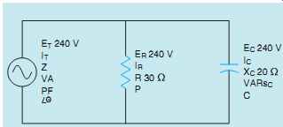
FIG. 3 An R-C parallel circuit.
R-C PARALLEL CIRCUITS
In any parallel circuit, the voltage is the same across all branches of the circuit. The voltage across the resistor and the voltage across the capacitor are, therefore, in phase with each other. In the branch containing resistance, the voltage and current are in phase with each other.
In the branch containing capacitance, the voltage and current are 90° out of phase with each other.
A circuit containing a resistor and capacitor connected in parallel is shown in FIG. 3. The circuit has an applied voltage of 240 volts at a frequency of 60 Hz. The resistor has a resistance of 30 Ohm, and the capacitor has a capacitive reactance of 20 Ohm. The following values will be determined for this circuit:
IR - Current flow through the resistor
P - Watts (true power)
IC - Current flow through the capacitor
VARsC - Reactive power
C - Capacitance of the capacitor
IT - Total circuit current
Z – Impedance
VA - Apparent power
PF - Power factor
θu - Angle theta (phase angle difference between voltage and current)
RESISTIVE CURRENT
The amount of current flow through the resistor can be determined using the values that apply to the resistor. The formula for determining the resistive current will be:
IR = ER R IR = 240 30 IR = 8 Amps
TRUE POWER
The true power, or watts, for this circuit can be determined using the values that pertain to the resistive part of the circuit. The true power will be calculated using the formula:
P = E x IR P = 240 x 8 P = 1920 Watts
CAPACITIVE CURRENT
The amount of current flow through the capacitor (IC) can be computed using values that apply to the capacitive part of the circuit. The formula used will be:
IC = EC XC IC = 240 20 IC = 12 Amps
REACTIVE POWER (VARs)
The reactive power can be found using any of the capacitive values. In this example, the formula used will be:
VARsC = E2 C XC VARsC = 2402 20 VARsC = 2880
CAPACITANCE
The capacitance of the capacitor can be determined using the formula:
C = 1 2pF XC C = 1 377 x 20 C = 0.0001326 F or 132.6 µF
TOTAL CURRENT
As stated previously, the current in the resistive part of the circuit is in phase with the voltage, and the current in the capacitive part of the circuit leads the voltage by 90°. In a parallel circuit, the sum of the currents through each branch will equal the total current. Because these two currents are out of phase with each other, vector addition must be used. The formula for determining the total circuit current is:

IMPEDANCE
The impedance can be determined in several ways.
One is to use the total circuit value, as shown in this formula:
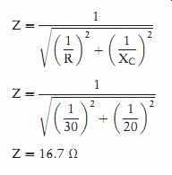
Z = ET IT Z = 240 14:4 Z = 16.7 Ohm
The impedance can also be found by adding the reciprocals of the resistance and capacitive reactance. Because these two values are 90° out of phase with each other, vector addition must be used.

APPARENT POWER
The apparent power (VA) can be computed by multiplying the circuit voltage and the total current together.
VA = E x IT VA = 240 x 14.4 VA = 3456
POWER FACTOR
The power factor is the ratio of the true power to the apparent power. The circuit power factor can be computed using any pure resistive value and total value. The power factor in this example will be determined using the formula:
PF = P VA
PF = 1920 3456
PF = 0.555 or 55.5%
ANGLE THETA
The cosine of angle theta is equal to the decimal equivalent of the power factor.
COS θu = 0.555
θu = 56.3° The voltage and current are 56.3° out of phase with each other in this circuit.
SUMMARY
R-C SERIES CIRCUITS
• In a pure resistive circuit, the voltage and current are in phase with each other.
• In a pure capacitive circuit, the current leads the voltage by 90°.
• In a circuit that contains both resistance and capacitance, the voltage and current will be out of phase with each other by some amount between 0° and 90°.
• The amount of phase angle shift between voltage and current in an R-C series is determined by the ratio of resistance and capacitance.
• In any series circuit, the current is the same through all components. Therefore, the voltage drops across the components are out of phase with each other.
• True power can be produced by the resistive parts of the circuit only.
• Power factor is the ratio of true power to apparent power.
R-C PARALLEL CIRCUITS
• The current flow through the resistive part of the circuit is in phase with the voltage.
• The current flow through the capacitive part of the circuit leads the voltage by 90°.
• Vector addition must be used to calculate the total circuit current when the resistive and capacitive currents are known.
• The voltage is the same across all branches of a parallel circuit.
• The power factor of any circuit containing resistance and capacitance will be a leading power factor.
QUIZ
1. In a pure capacitive circuit, does the current lead or lag the voltage?
2. A series circuit contains a 20-Ohm resistor and a capacitor with a capacitance of 110.5 µF. If the circuit has a frequency of 60 Hz, what is the total impedance of the circuit?
3. An R-C series circuit has a power factor of 76%. By how many degrees are the voltage and current out of phase with each other?
4. An R-C series circuit has a total impedance of 84 Ohm. The resistor has a value of 32 Ohm. What is the capacitive reactance of the capacitor?
XC = __/ Z2 _R2
5. A capacitor has a capacitive reactance of 50 Ohm when connected to 60 Hz. What will be the capacitive reactance if the capacitor is connected to 1000 Hz?
6. A capacitor and resistor are connected in parallel to a 120-V, 60-Hz line. The resistor has a resistance of 40 Ohm, and the capacitor has a capacitance of 132.6 µF. What is the total current flow in the circuit?
7. What is the impedance of the circuit in question 6?
8. What is the power factor of the circuit in question 6?
9. How many degrees out of phase are the voltage and current in question 6?
10. An R-C parallel circuit has a current flow of 3.2 A when connected to 120 V at 60 Hz. What is the impedance of this circuit?
PRACTICE PROBLEMS: R-C SERIES CIRCUITS
Refer to the Resistive-Capacitive Series Circuit formula section in Appendix C and to FIG. 1 to answer the following questions.
1. Assume that the circuit shown in FIG. 1 is connected to a 480-V, 60-Hz line. The capacitor has a capacitance of 165.782 µF, and the resistor has a resistance of 12 Ohm.
Find all the missing values.
ET 480 V ER EC IT IR IC Z R12 O XC VA P VARsC PF θu C 165.782 µF
2. Assume that the circuit shown in FIG. 1 has a voltage drop across the resistor (ER) of 78 volts, the voltage drop across the capacitor (EC) is 104 volts. The circuit has a total impedance of 20 Ohm. The frequency of the AC voltage is 60 Hz.
Find all the missing values.
ET ER =78V EC = 104 V IT IR IC Z=20 O R XC VA P VARsC PF θu C
3. Assume that the circuit shown in FIG. 1 has an apparent power of 432 VA and a true power of 345.6 W.
The capacitor has a capacitance of 15.8919 µF, and the frequency is 60 Hz. Find all the missing values.
ET ER EC IT IR IC Z R XC VA = 432 P = 345.6 W VARsC PF θu C = 15.8919 µF
R-C PARALLEL CIRCUITS
Refer to the formulas in the Resistive-Capacitive Parallel Circuits section of Appendix C. Also refer to the circuit shown in FIG. 3.
4. Assume that the circuit shown in FIG. 3 is connected to a 60-Hz line and has a total current flow of 10.463 A. The capacitor has a capacitance of 132.626 µF, and the resistor has a resistance of 14 Ohm.
Find all the missing values.
ET ER EC IT = 10.463 A IR IC Z R=14 Ohm XC VA P VARsC PF θu C = 132.626 µF
5. Assume that the circuit shown in FIG. 3 is connected to 400 Hz and has a total impedance of 21.6 Ohm.
The resistor has a resistance of 36 Ohm, and the capacitor has a current of 2 A flowing through it. Find all the missing values.
ET ER EC IT IR IC =2A
Z = 21.6 Ohm
R=36 Ohm
XC VA P VARsC PF θu C
6. Assume that the circuit shown in FIG. 3 is connected to a 600 Hz line and has a current flow through the resistor of 65.6 A and a current flow through the capacitor of 124.8 A. The total impedance of the circuit is 2.17888 Ohm. Find all the missing values.
ET ER EC IT IR = 56.6 A IC = 124.8 A Z = 2.17888 Ohm
R XC VA P VARsC PF θu C
REAL-WORLD APPLICATIONS
1. A 120-V incandescent pilot lamp must be connected to 480 V. A capacitor is to be connected in series to limit the current to prevent damage to the lamp. The lamp is rated at 3 W. What size capacitor should be connected in series with the lamp, and what is the minimum voltage rating of the capacitor?
2. A single-phase, 240-V, 60-Hz AC motor has a current draw of 14 A when operating. A wattmeter indicates a true power of 1500 W.
Now assume that a 50 µF capacitor is connected in parallel with the motor.
Determine the following:
1 The power factor of the circuit before the capacitor is connected.
2 The circuit current after the capacitor has been connected.
3 The power factor circuit after the capacitor has been connected.
