AMAZON multi-meters discounts AMAZON oscilloscope discounts
LEARNING OBJECTIVES:
• list the three factors that determine the capacitance of a capacitor.
• discuss the electrostatic charge.
• discuss the differences between nonpolarized and polarized capacitors.
• compute values for series and parallel connections of capacitors.
• compute an RC time constant.
• explain why current appears to flow through a capacitor when it is connected to an alternating current circuit.
• discuss capacitive reactance.
• compute the value of capacitive reactance in an AC circuit.
• compute the value of capacitance in an AC circuit.
• discuss the relationship of voltage and current in a pure capacitive circuit.
GLOSSARY OF CAPACITOR TERMS
- appear to flow the charging and discharging of a capacitor will cause current to appear to flow through a capacitor when it is connected to an AC circuit
- capacitive reactance (Xc) the current-limiting effect of a capacitor
- dielectric the insulation between the plates of a capacitor
- dielectric stress the stretching of the molecular structure of the dielectric
- electrolytic a type of capacitor that is polarity sensitive
- electrostatic charge the charge of a capacitor produced by the stressing of the molecules in the dielectric
- exponential the rate at which a capacitor charges and discharges
- farad the unit measure of capacitance
- frequency the number of times per second that the current changes direction in an alternating current circuit
- HIPOT an instrument that develops a high potential or high voltage for testing the dielectric of a capacitor
- leakage current the amount of current that flows through the dielectric of a capacitor
- nonpolarized capacitors capacitors that are not sensitive to voltage polarity
- out of phase a condition that occurs between the voltage and current in a capacitive circuit
- plates thin, flat metal used in the construction of a capacitor
- polarized capacitors capacitors that are sensitive to voltage polarity
- reactive power (VARs) volt amps reactive; often called wattless power, VARs is the product of the current and voltage in a pure reactive load
- RC time constant the time required for a capacitor to charge or discharge when it is connected in series with a resistance
- surface area one of the factors that determines the amount of capacitance a capacitor will have
- variable capacitors capacitors that can be adjusted for different values of capacitance
- voltage rating the amount of voltage that can be safely applied to a capacitor without damaging the dielectric
- - - - - -
Capacitors perform a variety of jobs such as power factor correction, storing an electrical charge to produce a large current pulse, timing circuits, and electronic filters. Capacitors can be nonpolarized or polarized depending on the application.
Nonpolarized capacitors can be used in both AC and DC circuits, while polarized capacitors can be used in DC circuits only. Both types will be discussed in this unit.
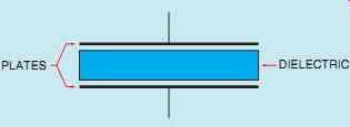
FIG. 1 A capacitor is made by separating two metal plates
by a dielectric.
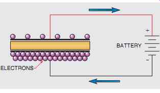
FIG. 2 A capacitor can be charged by removing electrons from one plate
and depositing them on the other plate.
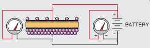
FIG. 3 Current flows until the voltage across the capacitor is equal
to the voltage of the battery.
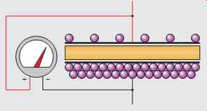
FIG. 4 The capacitor remains charged after the battery is removed from
the circuit.
CAPACITORS
CAUTION: It is the habit of some people to charge a capacitor to high voltage and then hand it to another person. While some people think this is comical, it is an extremely dangerous practice. Capacitors have the ability to supply an almost infinite amount of current.
Under some conditions, a capacitor can have enough energy to cause a person's heart to go into fibrillation.
This statement is not intended to strike fear in the heart of anyone working in the electrical field.
It is intended to make you realize the danger that capacitors can pose under certain conditions.
Capacitors are devices that oppose a change of voltage. The simplest type of capacitor is constructed by separating two metal plates by some type of insulating material called the dielectric (FIG. 1). Three factors determine the capacitance of a capacitor:
1. The area of the plates.
2. The distance between the plates.
3. The type of dielectric used.
The greater the surface area of the plates, the more capacitance a capacitor will have. If a capacitor is charged by connecting it to a source of direct current (FIG. 2), electrons are removed from the plate connected to the positive battery terminal and are deposited on the plate connected to the negative terminal. This flow of current will continue until a voltage equal to the battery voltage is established across the plates of the capacitor (FIG. 3).
When these two voltages become equal, the flow of electrons stops. The capacitor is now charged. If the battery is disconnected from the capacitor, the capacitor will remain charged as long as there is no path by which the electrons can move from one plate to the other (FIG. 4). A good rule to remember concerning a capacitor and current flow is that current can flow only during the period of time that a capacitor is either charging or discharging.
In theory, it should be possible for a capacitor to remain in a charged condition forever. In actual practice, however, it cannot. No dielectric is a perfect insulator, and electrons eventually move through the dielectric from the negative plate to the positive, causing the capacitor to discharge (FIG. 5). This current flow through the dielectric is called leakage current and is proportional to the resistance of the dielectric and the charge across the plates. If the dielectric of a capacitor becomes weak, it will permit an excessive amount of leakage current to flow. A capacitor in this condition is often referred to as a leaky capacitor.
FIG. 4 The capacitor remains charged after the battery is removed from
the circuit.
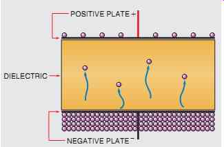
FIG. 5 Electrons eventually leak through the dielectric. This flow of
electrons is known as leakage current.
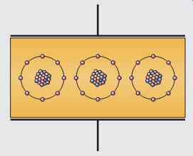
FIG. 6 Atoms of the dielectric in an uncharged capacitor.
ELECTROSTATIC CHARGE
Two other factors that determine capacitance are the type of dielectric used and the distance between the plates. To understand these concepts, it is necessary to understand how a capacitor stores energy. Previous chapters stated that an inductor stores energy in the form of an electro magnetic field. A capacitor stores energy in an electrostatic field.
The term electrostatic refers to electrical charges that are stationary, or not moving. They are very similar to the static electric charges that form on objects that are good insulators. The electrostatic field is formed when electrons are removed from one plate and deposited on the other.
DIELECTRIC STRESS
When a capacitor is not charged, the atoms of the dielectric are uniform, as shown in FIG. 6.
The valence electrons orbit the nucleus in a circular pattern. When the capacitor becomes charged, however, a potential exists between the plates of the capacitor. The plate with the lack of electrons has a positive charge, and the plate with the excess of electrons has a negative charge. Since electrons are negative particles, they are repelled away from the negative plate and attracted to the positive plate. This attraction causes the electron orbit to become stretched, as shown in FIG. 7. This stretching of the atoms of the dielectric is called dielectric stress. Placing the atoms of the dielectric under stress has the same effect as drawing back a bowstring with an arrow and holding it (FIG. 8); that is, it stores energy.
The amount of dielectric stress is proportional to the voltage difference between the plates. The greater the voltage, the greater the dielectric stress.
If the voltage becomes too great, the dielectric will break down and permit current to flow between the plates. At this point the capacitor becomes shorted. Capacitors have a voltage rating that should not be exceeded. The voltage rating indicates the maximum amount of voltage the dielectric is intended to withstand without breaking down. The amount of voltage applied to a capacitor is critical to its life span. Capacitors operated above their voltage rating will fail relatively quickly. Many years ago, the U.S. military made a study of the voltage rating of a capacitor relative to its life span. The results showed that a capacitor operated at one-half its rated voltage has a life span approximately eight times longer than a capacitor operated at the rated voltage.
The energy of the capacitor is stored in the dielectric in the form of an electrostatic charge. It is this electrostatic charge that permits the capacitor to produce extremely high currents under certain conditions. If the leads of a capacitor are shorted together, it has the effect of releasing the drawn-back bowstring (FIG. 8). When the bow string is released, the arrow is propelled forward at a high rate of speed. The same is true for the capacitor. When the leads are shorted, the atoms of the dielectric snap back to their normal position.
Shorting causes the electrons on the negative plate to be blown off and attracted to the positive plate.
Capacitors can produce currents of thousands of amperes for short periods of time.
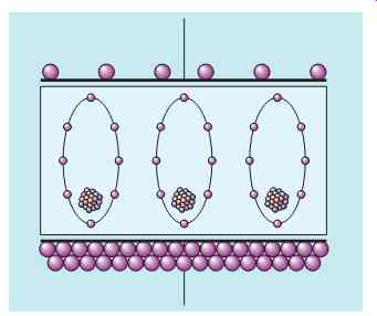
FIG. 7 Atoms of the dielectric in a charged capacitor.
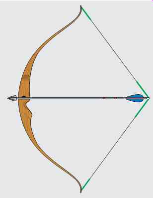
FIG. 8 Dielectric stress is similar to drawing back a bowstring with
an arrow and holding it.
This principle is used to operate the electronic flash of many cameras. Electronic flash attachments contain a small glass tube filled with a gas called xenon. Xenon produces a very bright white light similar to sunlight when the gas is ionized. A large amount of power is required, however, to produce a bright flash. A battery capable of directly ionizing the xenon would be very large and expensive, and would have a potential of about 500 V. The simple circuit shown in FIG. 9 can be used to overcome the problem. In this circuit, two small 1.5-V batteries are connected to an oscillator. The oscillator changes the direct current of the batteries into square wave alternating current. The alternating current is then connected to a transformer, and the voltage is increased to about 500 V peak.
A diode changes the AC voltage back into DC and charges a capacitor. The capacitor charges to the peak value of the voltage waveform. When the switch is closed, the capacitor suddenly discharges through the xenon tube and supplies the power needed to ionize the gas. It may take several seconds to store enough energy in the capacitor to ionize the gas in the tube, but the capacitor can release the stored energy in a fraction of a second.
To understand how the capacitor can supply the energy needed, consider the amount of gun powder contained in a 0.357 cartridge. If the powder were to be removed from the cartridge and burned in the open air, the actual amount of energy contained in the powder would be very small. This amount of energy would not even raise the temperature by a noticeable amount in a small enclosed room. If the same amount of energy is converted into heat in a fraction of a second, however, enough force is developed to propel a heavy projectile with great force. This same principle is at work when a capacitor is charged over some period of time and then discharged in a fraction of a second.
DIELECTRIC CONSTANTS
Since much of the capacitor's energy is stored in the dielectric, the type of dielectric used is extremely important in determining the amount of capacitance a capacitor will have. Different materials are assigned a number, called the dielectric constant. Air is assigned the number 1 and is used as a reference for comparison. For example, assume a capacitor uses air as the dielectric and its capacitance value is found to be 1 microfarad (µF).
Now assume that some dielectric material is placed between the plates without changing the spacing, and the capacitance value becomes 5 µF. This material has a dielectric constant of 5. A chart showing the dielectric constant of different materials is shown in FIG. 10.
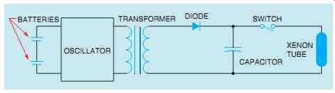
FIG. 9 Energy is stored in a capacitor.
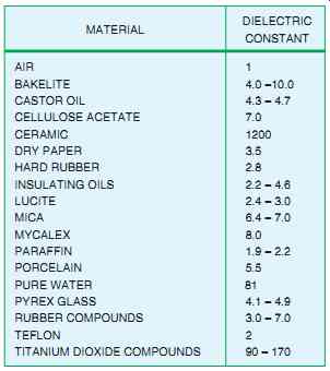
FIG. 10 Dielectric constant of different materials.
CAPACITOR RATINGS
The basic unit of capacitance is the farad, which is symbolized by the letter F. It receives its name from a famous scientist named Michael Faraday. A capacitor has a capacitance of one farad when a change of one volt across its plates results in a movement of one coulomb.
Q = C x V
where Q = charge in coulombs C = capacitance in farads V = charging voltage
Although the farad is the basic unit of capacitance, it is seldom used because it is an extremely large amount of capacitance. The following formula can be used to determine the capacitance of a capacitor when the area of the plates, the dielectric constant, and the distance between the plates are known.
C = K x A /4.45 D
where C = capacitance in pF (picofarads) K = dielectric constant A = area of one plate in square inches D = distance between the plates in inches
CAPACITORS CONNECTED IN PARALLEL
Connecting capacitors in parallel (FIG. 11) has the same effect as increasing the plate area of one capacitor. In the example shown, three capacitors having a capacitance of 20 µF, 30 µF, and 60 µF are connected in parallel. The total capacitance of this connection is:
CT = C1 + C2 + C3
CT = 20 + 30 + 60 CT = 110 µF
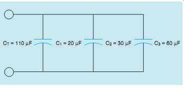
FIG. 11 Capacitors connected in parallel.
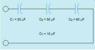
FIG. 12 Capacitors connected in series.
CAPACITORS CONNECTED IN SERIES
Connecting capacitors in series (FIG. 12) has the effect of increasing the distance between the plates, thus reducing the total capacitance of the circuit.
The total capacitance can be computed in a manner similar to computing parallel resistance. The following formulas can be used to find the total capacitance when capacitors are connected in series.
where
C = capacitance of one capacitor
N = number of capacitors connected in series (Note: The last formula can be used only when all the capacitors connected in series are of the same value.)
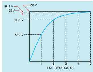
FIG. 13 Capacitors charge at an exponential rate.
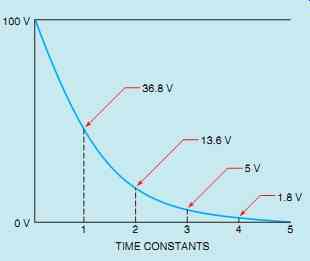
FIG. 14 Capacitor discharge curve.
CAPACITIVE CHARGE AND DISCHARGE RATES
Capacitors charge and discharge at an exponential rate. A charge curve for a capacitor is shown in FIG. 13. The curve is divided into five time constants, and each time constant is equal to 63.2% of the whole value. In FIG. 13,itis assumed that a capacitor is to be charged to a total of 100 V. At the end of the first time constant, the voltage has reached 63.2% of 100, or 63.2 V.
At the end of the second time constant, the voltage reaches 63.2% of the remaining voltage, or 86.4 V.
This pattern continues until the capacitor has been charged to 100 V.
The capacitor discharges in the same manner (FIG. 14). At the end of the first time constant, the voltage will decrease by 63.2% of its charged value. In this example, the voltage will decrease from 100 V to 36.8 V in the first time constant.
At the end of the second time constant the voltage will drop to 13.6 V, and by the end of the third time constant the voltage will drop to 5 V. The voltage will continue to drop at this rate until it reaches approximately 0 after five time constants.
RC TIME CONSTANTS
When a capacitor is connected in a circuit with a resistor, the amount of time needed to charge the capacitor (that is, the RC time constant) can be determined very accurately (FIG. 15). The formula for determining charge time is
t = R x C
where
t = the time for one time constant in seconds R = resistance in ohms C = capacitance in farads The Greek letter t (tau) is used to represent the time for one time constant. It is not unusual, however, for the letter T to be used to represent time.
APPLICATIONS FOR CAPACITORS
Capacitors are among the most used of electrical components. They are used for power factor correction in industrial applications, in the start windings of many single-phase AC motors, to produce phase shifts for SCR and Triac circuits, to filter pulsating DC, and in RC timing circuits. (SCRs and Triacs are solid state electronic devices used throughout industry to control high-current circuits.) Capacitors are used extensively in electronic circuits for control of frequency and pulse generation. The type of capacitor is dictated by the circuit application.
FIG. 13 Capacitors charge at an exponential rate.
FIG. 14 Capacitor discharge curve.
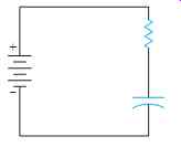
FIG. 15 The charge time of the capacitor can be determined very accurately.
METAL FOIL PAPER
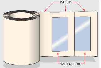
FIG. 18 Oil-filled paper capacitor.
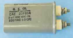
FIG. 17 Oil-filled paper capacitor.
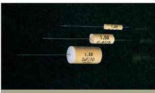
FIG. 16 Nonpolarized capacitors. Courtesy of Mallory Capacitor Co.
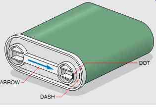
FIG. 19 Marks indicate plate nearest capacitor case.
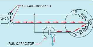
FIG. 20 Identified capacitor terminal connected to motor start winding
(incorrect connection).
NONPOLARIZED CAPACITORS
Capacitors can be divided into two basic groups, non polarized and polarized. Nonpolarized capacitors are often referred to as AC capacitors, because they are not sensitive to polarity connection. Nonpolarized capacitors can be connected to either DC or AC circuits without harm to the capacitor. Nonpolarized capacitors are constructed by separating metal plates with some type of dielectric (FIG. 1).
These capacitors come in many different styles and case types (FIG. 16).
A common type of AC capacitor called the paper capacitor or oil-filled capacitor is often used in motor circuits and for power factor correction (FIG. 17).
It derives its name from the type of dielectric used.
This capacitor is constructed by separating plates made of metal foil with thin sheets of paper soaked in a dielectric oil (FIG. 18). These capacitors are often used as the run or starting capacitor for single-phase motors. Many manufacturers of oil-filled capacitors will identify one terminal with an arrow or a painted dot, or by stamping a dash in the capacitor can (FIG. 19). This identified terminal marks the connection to the plate that is located nearer to the metal container or can. It has long been known that when a capacitor's dielectric breaks down and permits a short circuit to ground, the plate nearer to the outside case most often becomes grounded. For this reason, it is generally desirable to connect the identified capacitor terminal to the line side instead of to the motor start winding.
In FIG. 20, the run capacitor has been connected in such a manner that the identified terminal is connected to the start winding of a single phase motor. If the capacitor should become shorted to ground, a current path exists through the motor start winding. The start winding is an inductive type load, and inductive reactance will limit the value of current flow to ground. Since the flow of current is limited, it will take the circuit breaker or fuse some time to open the circuit and disconnect the motor from the power line. This time delay can permit the start winding to overheat and become damaged.
In FIG. 21, the run capacitor has been connected in the circuit so that the identified terminal is connected to the line side. If the capacitor should become shorted to ground, a current path exists directly to ground, bypassing the motor start winding. When the capacitor is connected in this manner, the start winding does not limit current flow and permits the fuse or circuit breaker to open the circuit almost immediately.
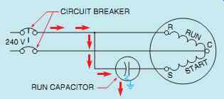
FIG. 21 Identified terminal connected to the line (correct connections).

FIG. 22 Polarized capacitors. Courtesy of Mallory Capacitor Co.
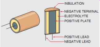
FIG. 23 Wet type electrolytic capacitor.
POLARIZED CAPACITORS
Polarized capacitors are generally referred to as electrolytic capacitors. These capacitors are sensitive to the polarity they are connected to and have one terminal identified as positive or negative (FIG. 22).
Polarized capacitors can be used in DC circuits only. If their polarity connection is reversed, the capacitor can be damaged and will sometimes explode. The advantage of electrolytic capacitors is that they can have very high capacitance in a small case.
There are two basic types of electrolytic capacitors, the wet type and the dry type. The wet type electrolytic (FIG. 23) has a positive plate made of aluminum foil. The negative plate is actually an electrolyte made from a borax solution. A second piece of aluminum foil is placed in contact with the electrolyte and becomes the negative terminal.
When a source of direct current is connected to the capacitor, the borax solution forms an insulating oxide film on the positive plate. This film is only a few molecules thick and acts as the insulator to separate the plates. The capacitance is very high because the distance between the plates is so small.
If the polarity of the wet type electrolytic capacitor becomes reversed, the oxide insulating film dissolves and the capacitor becomes shorted.
If the polarity connection is corrected, the film reforms and restores the capacitor.
FIG. 24 Two wet type electrolytic capacitors connect to form an AC electrolytic
capacitor.
AC ELECTROLYTIC CAPACITORS
The ability of the wet type electrolytic capacitor to be shorted and then reformed is the basis for a special type of nonpolarized AC electrolytic capacitor. It is used as the starting capacitor for many small single-phase motors, as the run capacitor in many ceiling fan motors, and for low-power electronic circuits when a nonpolarized capacitor with a high capacitance is required. The AC electrolytic capacitor is made by connecting two wet type electrolytic capacitors inside the same case (FIG. 24). In the example shown their negative terminals are connected. When alternating current is applied to the leads, one capacitor will be connected to reverse polarity and become shorted. The other capacitor will be connected to the correct polarity and will form. During the next half cycle, the polarity changes and forms the capacitor that was shorted and shorts the other capacitor. An AC electrolytic capacitor is shown in FIG. 25.
DRY TYPE ELECTROLYTIC CAPACITORS
The dry type electrolytic capacitor is very similar to the wet type except that gauze is used to hold the borax solution. This prevents the capacitor from leaking. Although the dry type electrolytic has the advantage of being relatively leak proof, it does have one disadvantage. If the polarity connection is reversed and the oxide film is broken down, it will not reform when connected to the proper polarity.
Reversing the polarity of a dry type electrolytic capacitor will permanently damage the capacitor.
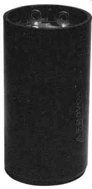
FIG. 25 An AC electrolytic capacitor.
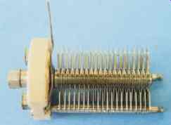
FIG. 26 A variable capacitor.
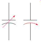
FIG. 28 Variable capacitor symbols.
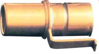
FIG. 27 A trimmer capacitor.
DC POWER SUPPLY MICROAMMETER CAPACITOR
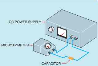
FIG. 29 Testing a capacitor for
leakage.
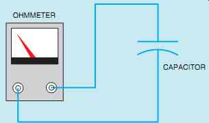
FIG. 30 Testing the capacitor with an ohmmeter.
VARIABLE CAPACITORS
Variable capacitors are constructed so their capacitance value can be changed over a certain range.
They generally contain a set of movable plates, which are connected to a shaft, and a set of stationary plates (FIG. 26). The movable plates can be interleaved with the stationary plates to increase or decrease the capacitance value.
Because air is used as the dielectric and the plate area is relatively small, variable capacitors are generally rated in picofarads. Another type of small variable capacitor is called the trimmer capacitor (FIG. 27). It has one movable plate and one stationary plate. The capacitance value is changed by turning an adjustment screw that moves the movable plate closer to or farther away from the stationary plate. FIG. 28 shows schematic symbols used to represent variable capacitors.
TESTING CAPACITORS
Testing capacitors is difficult at best. Small electrolytic capacitors are generally tested for shorts with an ohmmeter. If the capacitor is not shorted, it should be tested for leakage using a variable DC power sup ply and a microammeter (FIG. 29). When rated voltage is applied to the capacitor, the microammeter should indicate zero current flow.
Large AC oil-filled capacitors can be tested in a similar manner. To test the capacitor accurately, two measurements must be made. One is to mea sure the capacitance value of the capacitor to deter mine if it is the same or approximately the same as the rate value. The other is to test the strength of the dielectric.
The first test should be made with an ohmmeter.
With the power disconnected, connect the terminals of an ohmmeter directly across the capacitor terminals (FIG. 30). This test determines if the dielectric is shorted. When the ohmmeter is connected, the needle should swing up scale and return to infinity. The amount of needle swing is determined by the capacitance of the capacitor. Then reverse the ohmmeter connection, and the needle should move twice as far up scale and return to the infinity setting.
If the ohmmeter test is successful, the dielectric must be tested at its rated voltage with a dielectric strength test. To make this test, a dielectric test set must be used (FIG. 31). This device is often referred to as a HIPOT because of its ability to produce a high voltage or high potential. The dielectric test set contains a variable voltage control, a voltmeter, and a microammeter. To use the HIPOT, connect its terminal leads to the capacitor terminals. Increase the output voltage until rated voltage is applied to the capacitor. The micro ammeter indicates any current flow between the plates of the dielectric. If the capacitor is good, the microammeter should indicate zero cur rent flow.
The capacitance value must be measured to determine if there are any open plates in the capacitor. To measure the capacitance value of the capacitor, connect some value of AC voltage across the plates of the capacitor (FIG. 32). This volt age must not be greater than the rated capacitor voltage. Then measure the amount of current flow in the circuit. Now that the voltage and cur rent flow are known, the capacitive reactance of the capacitor can be computed using the formula
Xc = E x I
After the capacitive reactance has been deter mined, the capacitance can be computed using the formula
C = 1 2pFXc
(Note: Capacitive reactance is measured in ohms and limits current flow in a manner similar to inductive reactance. Capacitive reactance is covered fully in this chapter.)
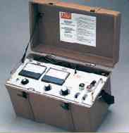
FIG. 31 A dielectric test set. Courtesy of Biddle Instruments.
PLATES DIELECTRIC
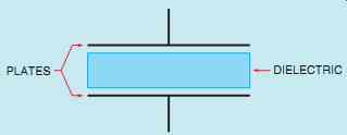
FIG. 33 A basic capacitor.
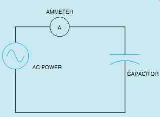
FIG. 32 Determining the capacitance value.
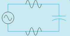
FIG. 35 A capacitor connected to an AC circuit.
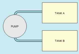
FIG. 34 Water can flow continuously, but not between the two tanks.
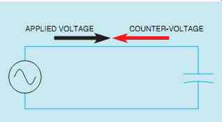
FIG. 36 Counter-voltage limits the flow of current.
CONNECTING THE CAPACITOR INTO AN AC CIRCUIT
When a capacitor (FIG. 33) is connected to an alternating current circuit, current will appear to flow through the capacitor. The reason is that in an AC circuit, the current continually changes direction and polarity. To understand this concept, consider the hydraulic circuit shown in FIG. 34.
Two tanks are connected to a common pump.
Assume tank A to be full and tank B to be empty.
Now assume that the pump pumps water from tank A to tank B. When tank B becomes full, the pump reverses and pumps the water from tank B back into tank A. Each time a tank is filled, the pump reverses and pumps water back into the other tank. Notice that water is continually flowing in this circuit, but there is no direct connection between the two tanks.
A similar action takes place when a capacitor is connected to an alternating current circuit (FIG. 35). In this circuit, the AC generator or alternator charges one plate of the capacitor positive and the other plate negative. During the next half cycle, the voltage will change polarity and the capacitor will discharge and recharge to the opposite polarity. As long as the voltage continues to increase, decrease, and change polarity, current will flow from one plate of the capacitor to the other. If an ammeter were placed in the circuit, it would indicate a continuous flow of current, giving the appearance that cur rent is flowing through the capacitor.
CAPACITIVE REACTANCE
As the capacitor is charged, an impressed voltage is developed across its plates as an electrostatic charge is built up (FIG. 36). The impressed voltage is the voltage provided by the electrostatic charge. It opposes the applied voltage and limits the flow of current in the circuit. This counter voltage is similar to the counter-voltage produced by an inductor. The counter-voltage developed by the capacitor is called reactance also. Because it is caused by capacitance, it is called capacitive reactance (Xc) and is measured in ohms. The formula for finding capacitive reactance is
XC = 1 2pFC
where XC = capacitive reactance
p = 3:1416
F = frequency in hertz
C = capacitance in farads
COMPUTING CAPACITANCE
If the value of capacitive reactance is known, the capacitance of the capacitor can be found using the formula
C = 1 2pFXC
VOLTAGE AND CURRENT RELATIONSHIPS IN A PURE CAPACITIVE CIRCUIT
Earlier in this text it was shown that the current in a pure resistive circuit is in phase with the applied voltage and that current in a pure inductive circuit lags the applied voltage by 90°. In this unit it will be shown that in a pure capacitive circuit the cur rent will lead the applied voltage by 90°.
When a capacitor is connected to an alternating current, the capacitor will charge and discharge at the same rate and time as the applied voltage. The charge in coulombs is equal to the capacitance of the capacitor times the applied voltage (Q = C x V).
When the applied voltage is zero, the charge in coulombs and impressed voltage will be zero also.
When the applied voltage reaches its maximum value-positive or negative-the charge in coulombs and impressed voltage will reach maximum also (FIG. 37). The impressed voltage will follow the same curve as the applied voltage.
In the waveform shown, voltage and charge are both zero at 0°. Since there is no charge on the capacitor, there is no opposition to current flow, which is shown to be maximum. As the applied voltage increases from zero toward its positive peak at 90°, the capacitor begins to charge at the same time. The charge produces an impressed voltage across the plates of the capacitor that opposes the flow of current. The impressed voltage is 180° out of phase with the applied voltage (FIG. 38).
When the applied voltage reaches 90° in the positive direction, the charge reaches maximum, the impressed voltage reaches peak in the negative direction, and the current flow is zero.
As the applied voltage begins to decrease, the capacitor begins to discharge, causing the current to flow in the opposite or negative direction. When the applied voltage and charge reach zero at 180°, the impressed voltage is zero also and the current flow is maximum in the negative direction. As the applied voltage and charge increase in the negative direction, the increase of the impressed voltage across the capacitor again causes the current to decrease. The applied voltage and charge reach maximum negative after 270° of rotation. The impressed voltage reaches maximum positive and the current has decreased to zero (FIG. 39). As the applied voltage decreases from its maximum negative value, the capacitor again begins to discharge. This causes the current to flow in the positive direction. The current again reaches its maximum positive value when the applied voltage and charge reach zero after 360° of rotation.
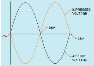
FIG. 38 The impressed voltage is 180° out of phase with the applied voltage.
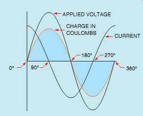
FIG. 37 Capacitive current leads the applied voltage by 90°.
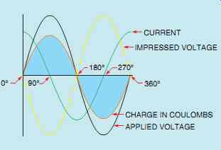
FIG. 39 Voltage, current, and charge relationships for a capacitive circuit.
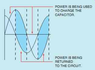
FIG. 40 A pure capacitive circuit has no true power (watts). The power
required to charge the capacitor is returned to the circuit when the capacitor
discharges.
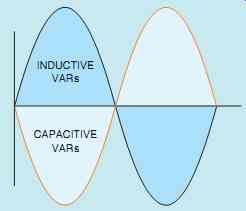
FIG. 41 Inductive VARs and capacitive VARs are 180° out of phase with
each other.
POWER IN A PURE CAPACITIVE CIRCUIT
Since the current flow in a pure capacitive circuit leads the applied voltage by 90°, the voltage and current have the same polarity for half of the time during one cycle and have opposite polarities the other half of the time (FIG. 40). During the period of time that the voltage and current have the same polarity, energy is being stored in the capacitor in the form of an electrostatic field.
When the voltage and current have opposite polarities, the capacitor is discharging, and the energy is returned to the circuit. When the values of current and voltage for one full cycle are added, the sum will equal zero just as it does with pure inductive circuits. Therefore, there is no true power, or watts, produced in a pure capacitive circuit.
The power value for a capacitor is reactive power and is measured in VARs, just as it is for an inductor. Inductive VARs and capacitive VARs are 180° out of phase with each other, however (FIG. 41). To distinguish between inductive and capacitive VARs, inductive VARs will be shown as VARsL and capacitive VARs as VARsC.
CAPACITOR VOLTAGE RATING
The voltage rating of a capacitor is actually the voltage rating of the dielectric. Voltage rating is extremely important concerning the life of the capacitor and should never be exceeded. Unfortunately, there are no set standards concerning how voltage ratings are marked. It is not unusual to see capacitors marked VOLTS AC, VOLTS DC, PEAK VOLTS, and WVDC (WORKING VOLTS DC).
The voltage rating of electrolytic or polarized capacitors will always be given in DC volts. The voltage rating of nonpolarized capacitors, however, can be given as AC or DC volts.
If a nonpolarized capacitor's voltage rating is given in AC volts, the voltage indicated is the RMS value. If the voltage rating is given as PEAK or as DC volts, it indicates the peak value of AC volts. If a capacitor is to be connected to an AC circuit, it is necessary to compute the peak value if the voltage rating is given as DC volts.
EFFECTS OF FREQUENCY IN A CAPACITIVE CIRCUIT
One of the factors that determine the capacitive reactance of a capacitor is the frequency. Capacitive reactance is inversely proportional to frequency. As the frequency increases, the capacitive reactance decreases. The chart in FIG. 42 shows the capacitive reactance for different values of capacitance at different frequencies. Frequency has an effect on capacitive reactance because the capacitor charges and discharges faster at a higher frequency. Recall that current is a rate of electron flow. A current of 1 A is one coulomb per second.
I = C t
where I = current C = charge in coulombs t = time in seconds
Assume that a capacitor is connected to a 30-Hz line, and 1 coulomb of charge flows each second.
If the frequency is doubled to 60 Hz, 1 coulomb of charge will flow in 0.5 s because the capacitor is being charged and discharged twice as fast (FIG. 43). This means that in a period of 1 s, 2 coulombs of charge will flow. Since the capacitor is being charged and discharged at a faster rate, the opposition to current flow is decreased.
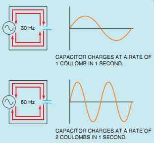
FIG. 43 The rate of charge increases with frequency.
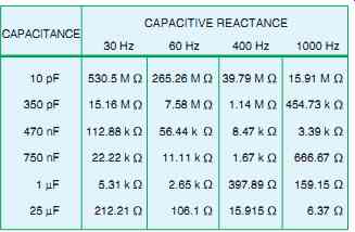
FIG. 42 Capacitive reactance is inversely proportional to frequency.
SUMMARY
• Capacitors are devices that oppose a change of voltage.
• Three factors that determine the capacitance of a capacitor are
A. The surface area of the plates.
B. The distance between the plates.
C. The type of dielectric.
• A capacitor stores energy in an electrostatic field.
• Current can flow only during the time a capacitor is charging or discharging.
• Capacitors charge and discharge at an exponential rate.
• The basic unit of capacitance is the farad.
• Capacitors are generally rated in microfarads, nanofarads, or picofarads.
• When capacitors are connected in parallel, their capacitance values add.
• When capacitors are connected in series, the reciprocal of the total capacitance is equal to the sum of the reciprocals of all the capacitors.
• The charge and discharge times of a capacitor are proportional to the amount of capacitance and resistance in the circuit.
• Five time constants are required to charge or discharge a capacitor.
• Nonpolarized capacitors are often called AC capacitors.
• Nonpolarized capacitors can be connected to direct or alternating current circuits.
• Polarized capacitors are often referred to as electrolytic capacitors.
• Polarized capacitors can be connected to direct current circuits only.
• There are two basic types of electrolytic capacitors, the wet type and the dry type.
• Wet type electrolytic capacitors can be reformed by reconnecting to the correct polarity.
• Dry type electrolytic capacitors will be permanently damaged if connected to the incorrect polarity.
• To test a capacitor for leakage, a microammeter should be connected in series with the capacitor and rated voltage applied to the circuit.
• When a capacitor is connected to an alternating current circuit, current will appear to flow through the capacitor.
• Current appears to flow through a capacitor because of the continuous increase and decrease of voltage and because of the continuous change of polarity in an AC circuit.
• The current flow in a pure capacitive circuit is limited by capacitive reactance.
• Capacitive reactance is proportional to the capacitance of the capacitor and the frequency of the AC line.
• Capacitive reactance is measured in ohms.
• In a pure capacitive circuit, the current leads the applied voltage by 90°.
• There is no true power, or watts, in a pure capacitive circuit.
• Capacitive power is reactive and is measured in VARs, as is inductance.
• Capacitive and inductive VARs are 180° out of phase with each other.
• Capacitor voltage ratings are given as volts AC, peak volts, and volts DC.
• A DC voltage rating for an AC capacitor indicates the peak value of voltage.
QUIZ
1. What is the dielectric?
2. List three factors that determine the capacitance of a capacitor.
3. A capacitor uses air as a dielectric and has a capacitance of 3 µF. A dielectric material is inserted between the plates without changing the spacing, and the capacitance becomes 15 µF. What is the dielectric constant of this material?
4. In what form is the energy of a capacitor stored?
5. Four capacitors having values of 20 µF, 50 µF, 40 µF, and 60 µF are connected in parallel. What is the total capacitance of this circuit?
6. If the four capacitors in question 5 were to be connected in series, what would be the total capacitance of the circuit?
7. A 22-µF capacitor is connected in series with a 90-kO resistor. How long will it take this capacitor to charge?
8. A 450-pF capacitor has a total charge time of 0.5 s. How much resistance is connected in series with the capacitor?
9. Can a nonpolarized capacitor be connected to a direct current circuit?
10. Explain how an AC electrolytic capacitor is constructed.
11. What type of electrolytic capacitor will be permanently damaged if connected to the incorrect polarity?
12. A 500-nF capacitor is connected to a 300-kO resistor. What is the total charge time of this capacitor?
13. Can current flow through a capacitor? 14. What two factors determine the capacitive reactance of a capacitor?
15. How many degrees are the current and voltage out of phase in a pure capacitive circuit?
16. Does the current in a pure capacitive circuit lead or lag the applied voltage?
17. A 30-µF capacitor is connected into a 240-V, 60-Hz circuit. What is the current flow in this circuit?
18. A capacitor is connected into a 1250-V, 1000-Hz circuit. The current flow is 80 A. What is the capacitance of the capacitor?
19. A capacitor is to be connected into a 480-V, 60-Hz line. If the capacitor has a voltage rating of 600 VDC, will the voltage rating of the capacitor be exceeded?
20. On the average, by what factor is the life expectancy of a capacitor increased if the capacitor is operated at half its voltage rating?
21. A capacitor is connected into a 277-V, 400-Hz circuit. The circuit current is 12 A. What is the capacitance of the capacitor?
22. A capacitor has a voltage rating of 350 VAC. Can this capacitor be connected into a 450-VDC circuit without exceeding the voltage rating of the capacitor?