AMAZON multi-meters discounts AMAZON oscilloscope discounts
OBJECTIVES
• discuss the operation of a parallel circuit containing resistance and inductance.
• compute circuit values of an R-L parallel circuit.
• connect an R-L parallel circuit and measure circuit values with test instruments.
RESISTIVE-INDUCTIVE PARALLEL CIRCUIT TERMS
- angle theta (θ u)--the phase angle difference between voltage and current in a circuit containing a reactive component such as an inductor or capacitor
- apparent power (VA) -- the value found by multiplying the applied voltage by the total current of an AC circuit. Apparent power is measured in volt-amps (VA) and should not be confused with true power, measured in watts
- current flow through the inductor (IL) --the amount of current flowing through the inductor
- current flow through the resistor (IR) --the amount of current flowing through the resistor
- power factor (PF) --the ratio of true power to apparent power reactive power VARs
- total current (IT) --the total current flow in an electric circuit; in an R-L parallel circuit it is determined by vector addition of the resistive current and inductive current
- total impedance (Z) --the total current-limiting effect in an AC circuit
- true power (P) --the amount of electrical energy that is converted into some other form of energy such as thermal or kinetic; also known as watts
- watts --the true power in a circuit; indicates the amount of electrical energy converted to some other form
----------------
This unit discusses circuits that contain resistance and inductance connected in parallel with each other.
Mathematical calculations will be used to show the relationship of current and voltage on the entire circuit, and the relationship of current through different branches of the circuit.
RESISTIVE-INDUCTIVE PARALLEL CIRCUITS
A circuit containing a resistor and an inductor connected in parallel is shown in FIG. 1.
Since the voltage applied to any device in parallel must be the same, the voltage applied to the resistor and inductor must be in phase and have the same value. The current flow through the inductor will be 90° out of phase with the volt age, and the current flow through the resistor will be in phase with the voltage (FIG. 2). This configuration produces a phase angle difference of 90° between the current flow through a pure inductive load and a pure resistive load (FIG. 3).
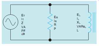
FIG. 1 A resistive-inductive parallel circuit.
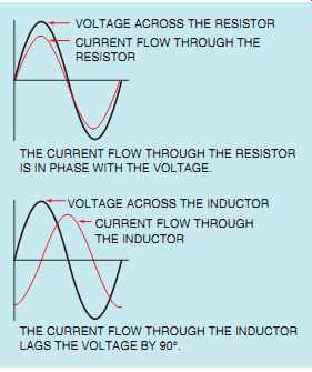
FIG. 2 Relationship of voltage and current in an R-L parallel circuit.
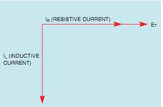
FIG. 3 Resistive and inductive currents are 90° out of phase with
each other in an R-L parallel circuit.
The amount of phase angle shift between the total circuit current and voltage is determined by the ratio of the amount of resistance to the amount of inductance. The circuit power factor is still determined by the ratio of apparent power to true power.
COMPUTING CIRCUIT VALUES
In the circuit shown in FIG. 4, a resistance of 15 Ohm is connected in parallel with an inductive reactance of 20 Ohm. The circuit is connected to a voltage of 240 V AC and a frequency of 60 Hz.
In this example problem, the following circuit values will be computed:
IR - current flow through the resistor
P - watts (true power)
IL - current flow through the inductor
VARs - reactive power
IT - total circuit current
Z - total circuit impedance
VA - apparent power
PF - power factor
θ u - the angle the voltage and current are out of phase with each other:
RESISTIVE CURRENT
In any parallel circuit, the voltage is the same across each component in the circuit. Therefore, 240 V are applied across both the resistor and the inductor.
Because the amount of voltage applied to the resistor is known, the amount of current flow through the resistor (IR) can be computed by using the formula:
IR = E/R
IR = 240/15
IR = 16 A
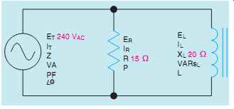
FIG. 4 Typical R-L parallel circuit.
WATTS
True power (P),or watts, can be computed using any of the watts formulas and pure resistive values.
The amount of true power in this circuit will be computed using the formula
P = ER x IR
P = 240 x 16
P = 3840 W
INDUCTIVE CURRENT
Because the voltage applied to the inductor is known, the current flow can be found by dividing the voltage by the inductive reactance. The amount of current flow through the inductor (IL) will be computed using the formula
IL = E/XL
IL = 240/20
IL = 12 A
VARS
The amount of reactive power, VARs, will be computed using the formula
VARs = EL x IL
VARs = 240 x 12
VARs = 2880
INDUCTANCE
The frequency and the inductive reactance are known, so the inductance of the coil can be found using the formula
L = XL 2pF
L = 20/377
L = 0.053H
TOTAL CURRENT
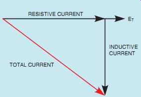
FIG. 5 Relationship of resistive, inductive, and total current in
an R-L parallel circuit.
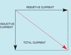
FIG. 6 Plotting total current using the parallelogram method.
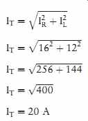
The total current (IT) flow through the circuit can be computed by adding the current flow through the resistor and the inductor. Since these two currents are 90° out of phase with each other, vector addition will be used. If these current values were plotted, they would form a right triangle similar to the one shown in FIG. 5. Notice that the current flow through the resistor and inductor form the legs of a right triangle, and the total current is the hypotenuse. Therefore, the Pythagorean theorem can be used to add these cur rents together.
The parallelogram method for plotting the total current is shown in FIG. 6.
IMPEDANCE
Now that the total current and total voltage are known, the total impedance (Z) can be computed by substituting Z for R in an Ohm's law formula.
The total impedance of the circuit can be computed using the formula

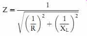
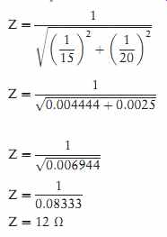
The value of impedance can also be found if total current and voltage are not known. In a parallel circuit, the reciprocal of the total resistance is equal to the sum of the reciprocals of each resistor. This same rule can be amended to permit a similar formula to be used in an R-L parallel circuit. Since resistance and inductive reactance are 90° out of phase with each other, vector addition must be used when the reciprocals are added. The initial formula is:

This formula states that the square of the reciprocal of the impedance is equal to the sum of the squares of the reciprocals of resistance and inductive reactance. To remove the square from the reciprocal of the impedance, take the square root of both sides of the equation.

Notice that the formula can now be used to find the reciprocal of the impedance, not the impedance. To change the formula so that it is equal to the impedance, take the reciprocal of both sides of the equation.
Numeric values can now be substituted in the formula to find the impedance of the circuit.
Another formula that can be used to determine the impedance of resistance and inductive reactance connected in parallel is
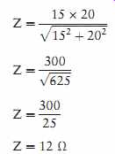
Substituting the same values for resistance and inductive reactance in this formula will result in the same answer.

APPARENT POWER
The apparent power (VA) can be computed by multiplying the circuit voltage by the total current flow. The relationship of volt-amps, watts, and VARs is the same for an R-L parallel circuit as it is for an R-L series circuit, because power adds in any type of circuit. Since the true power and reactive power are 90° out of phase with each other, they form a right triangle with apparent power as the hypotenuse (FIG. 7).
VA = ET x IT
VA = 240 x 20
VA = 4800
POWER FACTOR
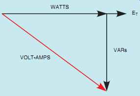
FIG. 7 Relationship of apparent power (volt amps), true power (watts),
and reactive power (VARs) in an R-L parallel circuit.
Power factor (PF) in an R-L parallel circuit is the relationship of apparent power to the true power just as it was in the R-L series circuit.
There are some differences in the formulas used to compute power factor in a parallel circuit, how ever. In an R-L series circuit, power factor could be computed by dividing the voltage dropped across the resistor by the total, or applied, voltage. In a parallel circuit, the voltage is the same, but the currents are different. Therefore, power factor can be computed by dividing the current flow through the resistive parts of the circuit by the total circuit current.
PF = IR/IT
Another formula that changes involves resistance and impedance. In a parallel circuit, the total circuit impedance will be less than the resistance. Therefore, if power factor is to be computed using impedance and resistance, the impedance must be divided by the resistance.
PF = Z/R
The circuit power factor in this example will be computed using the formula

ANGLE THETA
The cosine of angle theta (θ u) is equal to the power factor.
COSθ u = 0.80
θ u = 36.87°
A vector diagram using apparent power, true power, and reactive power is shown in FIG. 8.
Notice that angle theta is the angle produced by the apparent power and the true power. The relation ship of current and voltage for this circuit is shown in FIG. 9. The circuit with all values is shown in FIG. 10.
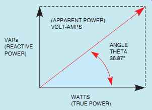
FIG. 8 Angle theta.
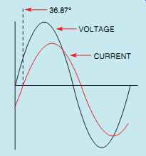
FIG. 9 The current is 36.87° out of phase with the voltage.
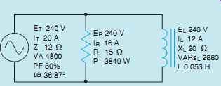
FIG. 10 All values have been found.
SUMMARY
• The voltage applied across components in a parallel circuit must be the same.
• The current flowing through resistive parts of the circuit will be in phase with the voltage.
• The current flowing through inductive parts of the circuit will lag the voltage by 90°.
• The total current in a parallel circuit is equal to the sum of the individual currents. Vector addition must be used because the current through the resistive parts of the circuit is 90°out of phase with the current flowing through the inductive parts.
• The impedance of an R-L parallel circuit can be computed using vector addition to add the reciprocals of the resistance and inductive reactance.
• Apparent power, true power, and reactive power add in any kind of circuit. Vector addition must be used, however, because true power and reactive power are 90° out of phase with each other.
QUIZ
1. When an inductor and resistor are connected in parallel, how many degrees out of phase are the current flow through the resistor and the current flow through the inductor?
2. An inductor and resistor are connected in parallel to a 120-V, 60-Hz line. The resistor has a resistance of 50 Ohm, and the inductor has an inductance of 0.2 H. What is the total current flow through the circuit?
3. What is the impedance of the circuit in question 2?
4. What is the power factor of the circuit in question 2?
5. How many degrees out of phase are the current and voltage in question 2?
6. In the circuit shown in FIG. 1, the resistor has a current flow of 6.5 A, and the inductor has a current flow of 8 A. What is the total cur rent in this circuit?
7. A resistor and inductor are connected in parallel. The resistor has a resistance of 24 Ohm, and the inductor has an inductive reactance of 20 Ohm. What is the impedance of this circuit?
8. The R-L parallel circuit shown in FIG. 1 has an apparent power of 325 VA. The circuit power factor is 66%. What is the true power in this circuit?
9. The R-L parallel circuit shown in FIG. 1 has an apparent power of 465 VA and a true power of 320 W. What is the reactive power?
10. How many degrees out of phase are the total current and voltage in question 9?
PRACTICE PROBLEMS
Refer to the circuit shown in FIG. 1.
Use the alternating current formulas in the Resistive-Inductive Parallel Circuits section of the appendix.
1. Assume that the circuit shown in FIG. 1 is connected to a 60-Hz line and has a total current flow of 34.553 A. The inductor has an inductance of 0.02122 H, and the resistor has a resistance of 14 Ohm.
ET ER EL IT 34.553 IR IL Z R14 XL VA P VARsL PF θ u L 0.02122
2. Assume that the current flow through the resistor, IR, is 15A; the current flow through the inductor, IL, is 36 A; and the circuit has an apparent power of 10,803 VA. The frequency of the AC voltage is 60 Hz.
ET ER EL IT IR 15 IL 36 Z R XL VA 10,803 P VARsL PF θ u L
3. Assume that the circuit in FIG. 1 has an apparent power of 144 VA and a true power of 115.2W. The inductor has an inductance of 0.15915 H, and the frequency is 60 Hz.
ET ER EL IT IR IL Z R XL VA 144 P 115.2 VARsL PF θ u L 0.15915
4. Assume that the circuit in FIG. 1 has a power factor of 78%, an apparent power of 374.817 VA, and a frequency of 400 Hz. The inductor has an inductance of 0.0382 H.
ET ER EL IT IR IL Z R XL VA 374.817 P VARsL PF 78% θ u L 0.0382
REAL-WORLD APPLICATIONS
1. Incandescent lighting of 500 W is connected in parallel with an inductive load. A clamp-on ammeter reveals a total circuit current of 7 A.
What is the inductance of the load connected in parallel with the incandescent lights? Assume a voltage of 120 V at 60 Hz.
2. You are working on a residential heat pump. The heat pump is connected to a 240-V, 60-Hz line. The compressor has a current draw of 34 A when operating. The compressor has a power factor of 70%. The back-up strip heat is rated at 10 kW. You need to know the amount of total current draw that will occur if the strip heat comes on while the compressor is operating.