AMAZON multi-meters discounts AMAZON oscilloscope discounts
OBJECTIVES
• discuss the relationship of resistance and inductance in an alternating current series circuit.
• define power factor.
• calculate values of voltage, current, apparent power, true power, reactive power, impedance, resistance, inductive reactance, and power factor in an R-L series circuit.
• compute the phase angle for current and voltage in an R-L series circuit.
• connect an R-L series circuit and make measurements using test instruments.
• discuss vectors and be able to plot electrical quantities using vectors.
RESISTIVE-INDUCTIVE SERIES CIRCUIT TERMS:
- angle theta (θ u) --the phase angle difference between voltage and current in a circuit containing a reactive component such as an inductor or capacitor
- apparent power volt amps (VA) --the product of the total applied voltage and the total current flow in an AC circuit
- parallelogram method --a method of obtaining values of voltage, current, impedance, and power with vectors
- power factor (PF) --the ratio of true power to apparent power
- quadrature power --often referred to as VARs, reactive power, or wattless power
- total current (IT) --the total current flow in an electric circuit
- total impedance (Z)-- the total current-limiting effect in an AC circuit
- true power-- the amount of electrical energy that is converted into some other form of energy such as thermal or kinetic; also known as watts
- vector --a line that indicates both magnitude and direction
- vector addition-- the process of using vectors to add like electrical values
- wattless power -- VARs; computed by using values that pertain only to reactive components such as inductors or capacitors
---------------------------
This unit will cover the relationship of resistance and inductance used in the same circuit. The resistors and inductors will be connected in series. Concepts such as circuit impedance, power factor, and vector addition will be introduced.
Although it is true that some circuits are basically purely resistive or purely inductive, many circuits contain a combination of both resistive and inductive elements.
R-L SERIES CIRCUITS
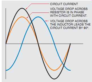
FIG. 1 Relationship of resistive and inductive current with voltage.
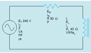
FIG. 2 R-L series circuit.
When a pure resistive load is connected to an alternating current circuit, the voltage and current are in phase with each other. When a pure inductive load is connected to an alternating current circuit, the voltage and current are 90° out of phase with each other (FIG. 1). When a circuit containing both resistance, R, and inductance, L, is connected to an alternating current circuit, the voltage and current will be out of phase with each other by an amount between 0° and 90°. The exact amount of phase angle difference is determined by the ratio of resistance as compared to inductance. In the following example, a series circuit containing 30 Ohm of resistance (R) and 40 Ohm of inductive reactance (XL) is connected to a 240-V, 60-Hz line (FIG. 2). It is assumed that the inductor has negligible resistance. The following unknown values will be computed:
Z - total circuit impedance
I - current flow
ER - voltage drop across the resistor
P - watts (true power)
L - inductance of the inductor
EL - voltage drop across the inductor
VARs - reactive power
VA - apparent power
PF - power factor
θ u - the angle the voltage and current are out of phase with each other
IMPEDANCE
In Section 12, impedance was defined as a mea sure of the part of the circuit that impedes, or hinders, the flow of current. It is measured in ohms and symbolized by the letter Z. In this circuit, impedance will be a combination of resistance and inductive reactance.
In a series circuit, the total resistance is equal to the sum of the individual resistors. In this instance, however, the total impedance (Z) will be the sum of the resistance and the inductive reactance. It would first appear that the sum of these two quantities should be 70 Ohm (30 Ohm + 40 Ohm = 70 Ohm). In practice, however, the resistive part of the circuit and the reactive part of the circuit are out of phase with each other by 90°. To find the sum of these two quantities, vector addition must be used.
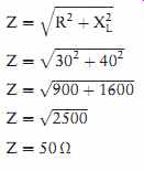
Because the quantities are 90° out of phase with each other, the resistive and inductive reactance form the two legs of a right triangle, and the impedance is the hypotenuse (FIG. 3).
The total impedance (Z) can be computed using the formula
VECTORS
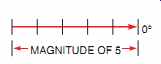
FIG. 4 A vector with a magnitude of 5 and an angle of 0°.
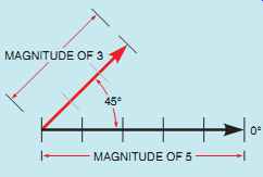
FIG. 5 A second vector with a magnitude of 3 and a direction of 45°.
Using the right triangle is just one method of graphically showing how out-of-phase quantities can be added. Another way is to use vectors. A vector is a line that indicates both magnitude and direction. The magnitude is indicated by its length, and the direction is indicated by its angle of rotation from 0°. Vectors should not be confused with scalars, which are used to represent magnitude only and do not take direction into consideration.
Imagine, for example, that you are in a strange city and you ask someone for directions to a certain building. If the person said to walk three blocks, that would be a scalar, because it contains only the magnitude, three blocks. If the person said to walk three blocks south, it would be a vector because it contains both the magnitude, three blocks, and the direction, south.
Zero degrees is indicated by a horizontal line. An arrow is placed at one end of the line to indicate direction. The magnitude can represent any quantity such as inches, meters, miles, volts, amps, ohms, or power.
A vector with a magnitude of 5 at an angle of 0° is shown in FIG. 4. Vectors rotate in a counter clockwise direction. Assume that a vector with a magnitude of 3 is to be drawn at a 45° angle from the first vector (FIG. 5). Now assume that a third vector with a magnitude of 4 is to be drawn in a direction of 120° (FIG. 6). Notice that the direction of the third vector is referenced from the horizontal 0° line and not from the second vector line, which was drawn at an angle of 45°.
ADDING VECTORS

FIG. 6 A third vector with a magnitude of 4 and a direction of 120°
is added.
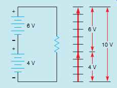
FIG. 7 Adding vectors in the same direction.
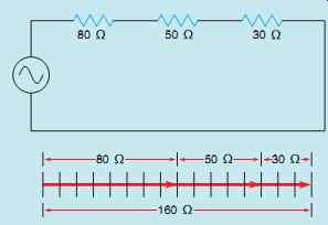
FIG. 8 Addition of series resistors.
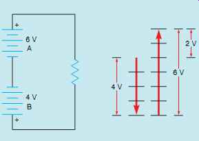
FIG. 9 Adding vectors with opposite directions.
Because vectors are used to represent quantities such as volts, amps, ohms, and power, they can be added, subtracted, multiplied, and divided. In electrical work, however, addition is the only function needed, so it will be the only one discussed.
Several methods can be used to add vectors.
Regardless of which is used, because vectors contain both magnitude and direction, they must be added with a combination of geometric and algebraic addition. This is often referred to as vector addition.
One method is to connect the starting point of one vector to the end point of another. This works especially well when all vectors are in the same direction. Consider the circuit shown in FIG. 7 in which two batteries, one rated at 6 V and the other at 4 V, are connected so that their voltages add. If vector addition is used, the starting point of one vector will be placed at the end point of the other. Notice that the sum of the two vector quantities is equal to the sum of the two voltages, 10 V.
Another example of this type of vector addition is shown in FIG. 8. In this example, three resistors are connected in series. The first resistor has a resistance of 80 Ohm, the second a resistance of 50 O, and the third a resistance of 30 Ohm. Because there is no phase angle shift of voltage or current, the impedance will be 160 Ohm, which is the sum of the resistances of the three resistors.
ADDING VECTORS WITH OPPOSITE DIRECTIONS
To add vectors that are exactly opposite in direction (180° apart), subtract the magnitude of the larger vector from the magnitude of the smaller.
The resultant is a vector with the same direction as the vector with the larger magnitude. If one of the batteries in FIG. 7 were reversed, the two voltages would oppose each other (FIG. 9). This means that 4 V of the 6-V battery A would have to be used to overcome the voltage of battery B. The resultant would be a vector with a magnitude of 2 V in the same direction as the 6-V battery. In algebra, this is the same operation as adding a positive number and a negative number (6 + [-4] = 2). When the -4 is brought out of brackets, the equation becomes 6 - 4 = 2.
ADDING VECTORS OF DIFFERENT DIRECTIONS
Vectors that have directions other than 180° from each other can also be added. FIG. 10 illustrates the addition of a vector with a magnitude of 4 and a direction of 15° to a vector with a magnitude of 3 and a direction of 60°. The addition is made by connecting the starting point of the second vector to the ending point of the first vector.
The resultant is drawn from the starting point of the first vector to the ending point of the second. It is possible to add several different vectors using this method. FIG. 11 illustrates the addition of several different vectors and the resultant.
To find the impedance of the circuit in FIG. 3 using this method of vector addition, connect the starting point of one vector to the ending point of the other. Since resistance and inductive reactance are 90° out of phase with each other, the two vectors must be placed at a 90° angle. If the resistive vector has a magnitude of 30 Ohm and the inductive vector has a magnitude of 40 Ohm, the resultant (impedance) will have a magnitude of 50 Ohm (FIG. 12). Notice that the result is the same as that found using the right triangle.
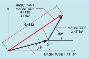
FIG. 10 Adding two vectors with different directions.
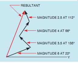
FIG. 11 Adding vectors with different magnitude and direction.
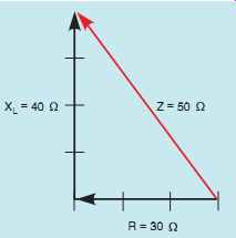
FIG. 12 Determining impedance using vector addition.
THE PARALLELOGRAM METHOD OF VECTOR ADDITION
The parallelogram method can be used to find the resultant of two vectors that originate at the same point. A parallelogram is a four-sided figure whose opposite sides form parallel lines. A rectangle, for example, is a parallelogram with 90° angles. Assume that a vector with a magnitude of 24 and a direction of 26° is to be added to a vector with a magnitude of 18 and a direction of 58°. Also assume that the two vectors originate from the same point (FIG. 13). To find the resultant of these two vectors, form a parallelogram using the vectors as two of the sides. The resultant is drawn from the corner of the parallelogram where the two vectors intersect to the opposite corner (FIG. 14).
Another example of the parallelogram method of vector addition is shown in FIG. 15. In this example, one vector has a magnitude of 50 and a direction of 32°. The second vector has a magnitude of 60 and a direction of 120°. The resultant is found by using the two vectors as two sides of a parallelogram.
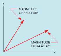
FIG. 13 Vectors that originate from the same point.
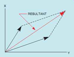
FIG. 14 The parallelogram method of vector addition.
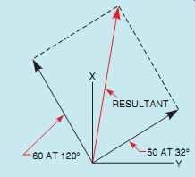
FIG. 15 The parallelogram method of vector addition, Example 2.
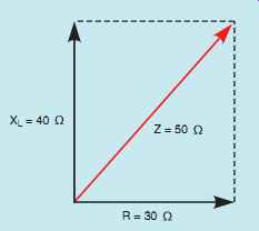
FIG. 16 Finding the impedance of the circuit using the parallelogram
method of vector addition.
FIG. 17 Total voltage divided by impedance equals total current.
The parallelogram method of vector addition can also be used to find the total impedance of the circuit shown in FIG. 2. The resistance forms a vector with a magnitude of 30 Ohm and a direction of 0°. The inductive reactance forms a vector with a magnitude of 40 Ohm and a direction of 90°.
When lines are extended to form a parallelogram and a resultant is drawn, the resultant will have a magnitude of 50 Ohm, which is the impedance of the circuit (FIG. 16). Some students of electricity find the right triangle concept easier to understand, and others find vectors more helpful. For this reason, this text will use both methods to help explain the relationship of voltage, current, and power in alternating current circuits.
TOTAL CURRENT
One of the primary laws for series circuits is that the current must be the same in any part of the circuit. This law holds true of R-L series circuits also. Since the impedance is the total current limiting component of the circuit, it can replace R in an Ohm's law formula. The total current (I) flow through the circuit can be computed by dividing the total applied voltage by the total current-limiting factor. Total current can be found with the formula
IT = ET/Z
The total current for the circuit in FIG. 2, then, is
IT = 240/50
IT = 4.8A
In a series circuit, the current is the same at any point in the circuit. Therefore, 4.8 A of current flow through both the resistor and the inductor.
These values can be added to the circuit as shown in FIG. 17.
VOLTAGE DROP ACROSS THE RESISTOR
Now that the amount of current flow through the resistor is known, the voltage drop across the resistor (ER) can be computed using the formula
ER = IR x R
The voltage drop across the resistor in our circuit is
ER = 4.8 x 30 ER = 144 V
Notice that the amount of voltage dropped across the resistor was found using quantities that pertained only to the resistive part of the circuit.
The amount of voltage dropped across the resistor could not be found using a formula such as ER = IR x XL or ER = IR x Z Inductive reactance (XL) is an inductive quantity and impedance (Z) is a circuit total quantity.
These quantities cannot be used with Ohm's law to find resistive quantities. They can, however, be used with vector addition to find like resistive quantities. For example, both inductive reactance and impedance are measured in ohms.
The resistive quantity measured in ohms is resistance (R). If the impedance and inductive reactance of a circuit were known, they could be used with the following formula to find the circuit resistance.
R= √Z^2- X^2 L
(Note: Refer to the Resistive-Inductive Series Circuits section of the alternating current formulas listed in the appendix.)
WATTS
True power (P) for the circuit can be computed by using any of the watts formulas with pure resistive parts of the circuit. Watts (W) can be computed, for example, by multiplying the volt age dropped across the resistor (ER) by the current flow through the resistor (IR); by squaring the voltage dropped across the resistor and dividing by the resistance of the resistor; or by squaring the current flow through the resistor and multiplying by the resistance of the resistor. Watts cannot be computed by multiplying the total voltage (ET) by the current flow through the resistor or by multiplying the square of the current by the inductive reactance. Recall that true power, or watts, can be produced only during periods of time when the voltage and current are both positive or both negative.
In an R-L series circuit, the current is the same through both the resistor and the inductor. The voltage dropped across the resistor, however, is in phase with the current, and the voltage dropped across the inductor is 90° out of phase with the current (FIG. 18). Since true power, or watts, can be produced only when the current and voltage are both positive or both negative, only resistive parts of the circuit can produce watts.
The formula used in this example will be


FIG. 18 Relationship of current and voltage in an R-L series circuit.
COMPUTING THE INDUCTANCE
The amount of inductance can be computed using the formula

VOLTAGE DROP ACROSS THE INDUCTOR
The voltage drop across the inductor (EL) can be computed using the formula

Notice that only inductive quantities were used to find the voltage drop across the inductor.
TOTAL VOLTAGE
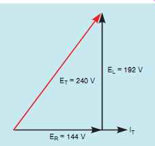
FIG. 19 Relationship of resistive and inductive voltage drops in
an R-L series circuit.
Although the total applied voltage in this circuit is known (240 V), the total voltage is also equal to the sum of the voltage drops, just as it is in any other series circuit. Since the voltage dropped across the resistor is in phase with the current and the voltage dropped across the inductor is 90° out of phase with the current, vector addition must be used. The total voltage will be the hypotenuse of a right triangle, and the resistive and inductive voltage drops will form the legs of the triangle (FIG. 19). This relationship of voltage drops can also be represented using the parallelogram method of vector addition as shown in FIG. 20. The following formulas can be used to find total volt age or the voltage drops across the resistor or inductor if the other two voltage values are known.

Note: Refer to the Resistive-Inductive Series Circuits section of the alternating current formulas listed in the appendix.
COMPUTING THE REACTIVE POWER
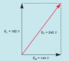
FIG. 20 Graphic representation of voltage drops using the parallelogram
method of vector addition.
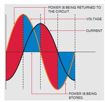
FIG. 21 Power is stored and then returned to the circuit.
VARs is an abbreviation for volt-amps-reactive and is the amount of reactive power (VARs) in the circuit. VARs should not be confused with watts, which is true power. VARs represents the product of the volts and amps that are 90° out of phase with each other, such as the voltage dropped across the inductor and the current flowing through the inductor. Recall that true power can be produced only during periods of time that the voltage and current are both positive or both negative (FIG. 21). During these periods, the power is being stored in the form of a magnetic field. During the periods that voltage and current have opposite signs, the power is returned to the circuit. For this reason, VARs is often referred to as quadrature power, or wattless power. It can be computed in a similar manner as watts except that reactive values of voltage and current are used instead of resistive values. In this example, the formula used is

COMPUTING THE APPARENT POWER
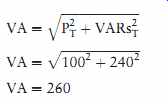
Volt-amperes (VA) is the apparent power of the circuit. It can be computed in a similar manner as watts or VARs, except that total values of voltage and current are used. It is called apparent power (VA) because it is the value found if a voltmeter and ammeter are used to measure the circuit volt age and current and these measured values are multiplied together (FIG. 22). In this example, the formula used is

FIG. 22 Apparent power is the product of measured values (240 V × 4.8 A = 1152 VA).
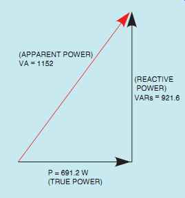
FIG. 23 Relationship of true power (watts), reactive power (VARs),
and apparent power (volt-amps) in an R-L series circuit.
The apparent power can also be found using vector addition in a similar manner as impedance or total voltage. Since true power, or watts, is a pure resistive component and VARs is a pure reactive component, they form the legs of a right triangle. The apparent power is the hypotenuse of the triangle (FIG. 23). This relationship of the three power components can also be plotted using the parallelogram method (FIG. 24). The following formulas can be used to compute the values of apparent power, true power, and reactive power when the other two values are known.
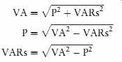
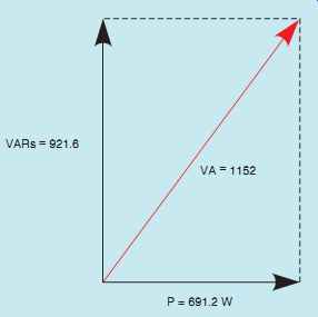
FIG. 24 Using the parallelogram method to plot the relationship of
volt-amps, watts, and VARs.
POWER FACTOR
Power factor (PF) is a ratio of the true power to the apparent power. It can be computed by dividing any resistive value by its like total value. For example, power factor can be computed by dividing the voltage drop across the resistor by the total circuit voltage; by resistance divided by impedance; or by watts divided by volt-amperes.

Power factor is generally expressed as a percentage. The decimal fraction computed from the division will, therefore, be changed to a percent by multiplying it by 100. In this circuit the formula will be

Note that in a series circuit, the power factor cannot be computed using current because current is the same in all parts of the circuit.
Power factor can become very important in an industrial application. Most power companies charge a substantial surcharge when the power factor drops below a certain percent. The reason for this is that electric power is sold on the basis of true power, or watts, consumed. The power company, however, must supply the apparent power. Assume that an industrial plant has a power factor of 60% and is consuming 5 MW (megawatts) of power per hour. At a power factor of 60%, the power company must actually supply 8.33 MVA (megavolt amps) (5 MW/0.6 = 8.33 MVA) per hour. If the power factor were to be corrected to 95%, the power company would have to supply only 5.26 MVA per hour to furnish the same amount of power to the plant.
ANGLE THETA
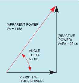
FIG. 25 The angle theta is the relationship of true power to apparent
power.
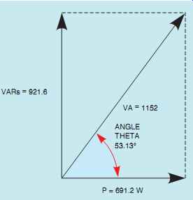
FIG. 26 The angle theta can be found using vectors provided by the
parallelogram method.
The angular displacement by which the voltage and current are out of phase with each other is called angle theta (θ u). Since the power factor is the ratio of true power to apparent power, the phase angle of voltage and current is formed between the resistive leg of the right triangle and the hypotenuse (FIG. 25). The resistive leg of the triangle is adjacent to the angle, and the total leg is the hypotenuse. The trigonometric function that corresponds to the adjacent side and the hypotenuse is the cosine. Angle theta will be the cosine of watts divided by volt-amps. Watts divided by volt-amps is also the power factor.
Therefore, the cosine of angle theta (θ u) is the power factor (PF).
COS θ u = PF
COS θ u = 0.6
θ u = 53.13°
The vectors formed using the parallelogram method of vector addition can also be used to find angle theta as shown in FIG. 26. Notice that the total quantity, volt-amps, and the resistive quantity, watts, again determine angle theta.
Since this circuit contains both resistance and inductance, the current is lagging the voltage by 53.13° (FIG. 27). Angle theta can also be determined by using any of the other trigonometric functions.


FIG. 27 Current and voltage are 53.13° out of phase with each other.
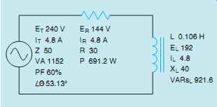
FIG. 28 Filling in all unknown values.
Now that all the unknown values have been computed, they can be filled in as shown in FIG. 28.
APPARENT POWER
Now that the total amount of true power and the total amount of reactive power are known, the apparent power (VA) can be computed using vector addition.
The parallelogram method of vector addition is shown in FIG. 32 for this calculation.
TOTAL CIRCUIT CURRENT
Now that the apparent power is known, the total circuit current can be found using the applied volt age and Ohm's law.

Since this is a series circuit, the current must be the same at all points in the circuit. The known values added to the circuit are shown in FIG. 33.
OTHER CIRCUIT VALUES
Now that the total circuit current has been found, other values can be computed using Ohm's law.
IMPEDANCE

POWER FACTOR

ANGLE THETA
Angle theta is the cosine of the power factor. A vector diagram showing this relationship is shown in FIG. 34.
=================
EXAMPLE 1
Two resistors and two inductors are connected in series (FIG. 29). The circuit is connected to a 130-V, 60-Hz line. The first resistor has a power dissipation of 56 W, and the second resistor has a power dissipation of 44 W. One inductor has a reactive power of 152 VARs and the second a reactive power of 88 VARs. Find the unknown values in this circuit.
Solution The first step is to find the total amount of true power and the total amount of reactive power. The total amount of true power can be computed by adding the values of the resistors together. A vector diagram of these two values would reveal that they both have a direction of 0° (FIG. 30).
PT 5P1 1P4 PT 556144 PT 5100 W
The total reactive power in the circuit can be found in the same manner. Like watts, the VARs are both inductive and are, therefore, in the same direction (FIG. 31). The total reactive power will be the sum of the two reactive power ratings.
VARsT 5VARsL2 1VARsL3 VARsT 5152188 VARsT 5240

FIG. 29 An R-L series circuit containing wo resistors and two inductors.

FIG. 30 The two true power (watts) vectors are in the same direction.

FIG. 31 The two reactive power (VARs) vectors are in the same direction.
=================
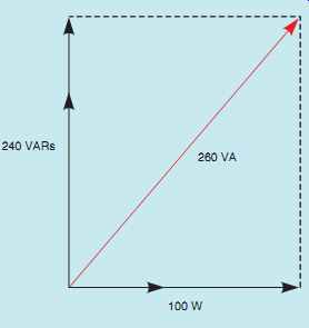
FIG. 32 Power vector for the circuit.
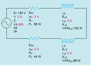
FIG. 33 Adding circuit values.
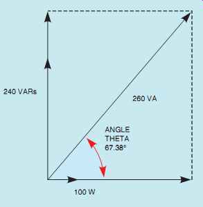
FIG. 34 Angle theta for the circuit.
FIG. 35 Voltage and current are 67.38° out of phase with each other.
COSθ u = PF COSθ u = 0.3846
θ u = 67.38°
The relationship of voltage and current for this circuit is shown in FIG. 35.
ER1
ER1 = P1 IR1 ER1 = 56 2 ER1 = 28 V

The complete circuit with all values is shown in FIG. 36.
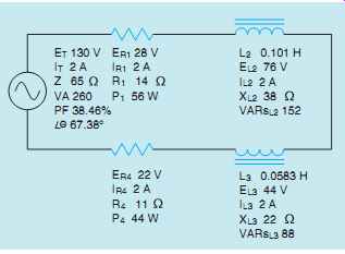
FIG. 36 All values for the circuit.
SUMMARY
• In a pure resistive circuit, the voltage and current are in phase with each other.
• In a pure inductive circuit, the voltage and cur rent are 90° out of phase with each other.
• In an R-L series circuit, the voltage and current will be out of phase with each other by some value between 0° and 90°.
• The amount the voltage and current are out of phase with each other is determined by the ratio of resistance to inductance.
• Total circuit values include total voltage, ET; total current, IT; volt-amps, VA; and impedance, Z.
• Pure resistive values include voltage drop across the resistor, ER; current flow through the resistor, IR; resistance, R; and watts, P.
• Pure inductive values include inductance of the inductor, L; voltage drop across the inductor, EL; current through the inductor, IL; inductive reactance, XL; and inductive VARs, VARsL.
• Angle theta measures the phase angle difference between the applied voltage and total circuit current.
• The cosine of angle theta is equal to the power factor.
• Power factor is a ratio of true power to apparent power.
• Vectors are lines that indicate both magnitude and direction.
QUIZ
1. What is the relationship of voltage and current (concerning phase angle) in a pure resistive circuit?
2. What is the relationship of voltage and current (concerning phase angle) in a pure inductive circuit?
3. What is power factor?
4. A circuit contains a 20-Ohm resistor and an inductor with an inductance of 0.093 H. If the circuit has a frequency of 60 Hz, what is the total impedance of the circuit?
5. An R-L series circuit has a power factor of 86%. How many degrees are the voltage and current out of phase with each other?
6. An R-L series circuit has an apparent power of 230 VA and a true power of 180 W. What is the reactive power?
7. The resistor in an R-L series circuit has a voltage drop of 53 V, and the inductor has a voltage drop of 28 V. What is the applied voltage of the circuit?
8. An R-L series circuit has a reactive power of 1234 VARs and an apparent power of 4329 VA. How many degrees are voltage and current out of phase with each other?
9. An R-L series circuit contains a resistor and an inductor. The resistor has a value of 6.5 Ohm. The circuit is connected to 120 V and has a current flow of 12 A. What is the inductive reactance of this circuit?
10. What is the voltage drop across the resistor in the circuit in question 9?
PRACTICE PROBLEMS
Refer to the circuit shown in FIG. 2 and the Resistive-Inductive Series Circuits section of the alternating current formulas listed in the appendix.
1. Assume that the circuit shown in FIG. 2 is connected to a 480-V, 60-Hz line. The inductor has an inductance of 0.053 H, and the resistor has a resistance of 12 Ohm.
ET 480 ER EL IT IR IL Z R12 XL VA P VARs PF θ u L 0.053 H
2. Assume that the voltage drop across the resistor, ER, is 78 V; that the voltage drop across the inductor, EL, is 104 V; and the circuit has a total impedance, Z, of 20 O. The frequency of the AC voltage is 60 Hz.
ET ER 78 EL104 V IT IR IL Z20 R XL VA P VARsL PF θ u L
3. Assume the above circuit has an apparent power of 144 VA and a true power of 115.2 W. The inductor has an inductance of 0.15915 H, and the frequency is 60 Hz.
ET ER EL IT IR IL Z R XL VA 144 P 115.2 W VARsL PF θ u L 0.15915 H
4. Assume the above circuit has a power factor of 78%, an apparent power of 374.817 VA, and a frequency of 400 Hz. The inductor has an inductance of 0.0382 H.
ET ER EL IT IR IL Z R XL VA 374.817 P VARsL PF 78% θ u L 0. 0382 H
REAL-WORLD APPLICATIONS
1. An AC single-phase motor is connected to a 240-V, 60-Hz circuit.
A clamp-on ammeter with a peak hold function reveals that the motor has an inrush current of 34 A when the motor is first started. Your job is to reduce the inrush current to a value of 20 A by connecting a resistor in series with the motor. The resistor will be shunted out of the circuit after the motor has started. Using an ohmmeter, you find that the motor has a wire resistance of 3 Ohm. How much resistance should be connected in series with the motor to reduce the starting current to 20 A?
2. You are a journeyman electrician working in an industrial plant. Your task is to connect an inductor to a 480-V, 60-Hz line. To determine the proper conductor and fuse size for this installation, you need to know the amount of current the inductor will draw from the line. The nameplate on the inductor indicates that the inductor has an inductance of 0.1 H. An ohmmeter reveals that it has a wire resistance of 10 Ohm. How much current should the inductor draw when power is applied?