AMAZON multi-meters discounts AMAZON oscilloscope discounts
OBJECTIVES:
• discuss the properties of inductance in an alternating current circuit.
• discuss inductive reactance.
• compute values of inductive reactance and inductance.
• discuss the relationship of voltage and current in a pure inductive circuit.
• be able to compute values for inductors connected in series or parallel.
• discuss reactive power (VARs).
• determine the Q of a coil.
INDUCTANCE IN ALTERNATING CURRENT CIRCUITS TERMS
- current lags voltage--the relationship of current and voltage in a pure inductive circuit
- impedance (Z) --the total current-limiting effect in an AC circuit
- induced voltage--voltage that is supplied to a conductor by cutting lines of magnetic flux
- inductance (L) --the property of an electric circuit whereby voltage is produced by cutting magnetic flux lines
- inductive reactance (XL) -- the current-limiting effect of a pure inductor
- quality (Q) --the ratio of inductive reactance as compared with resistance
- reactance --the property of a circuit that limits current by means other than resistance
- reactive power (VARs) -- Volt Amps Reactive; often referred to as wattless power
--------------------------------
This unit discusses the effects of inductance on alternating current circuits. The unit explains how cur rent is limited in an inductive circuit as well as the effect inductance has on the relation ship of voltage and current.
INDUCTANCE
Inductance (L) is one of the primary types of loads in alternating current circuits. Some amount of inductance is present in all alternating current circuits because of the continually changing magnetic field (FIG. 1). The amount of inductance of a single conductor is extremely small, and in most instances it is not considered in circuit calculations.
Circuits are generally considered to contain inductance when any type of load that contains a coil is used. For circuits that contain a coil, inductance is considered in circuit calculations. Loads such as motors, transformers, lighting ballast, and chokes all contain coils of wire.
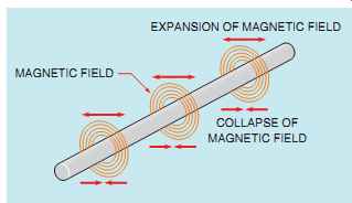
FIG. 1 A continually changing magnetic field induces a voltage into
any conductor.
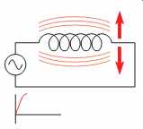
FIG. 2 As current flows through a coil, a magnetic field is created
around the coil.
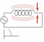
FIG. 3 As current flow decreases, the magnetic field collapses.
In Section 10, it was discussed that whenever current flows through a coil of wire a magnetic field is created around the wire (FIG. 2). If the amount of current decreases, the magnetic field will collapse (FIG. 3). Recall from Section 10 several facts concerning inductance:
1. When magnetic lines of flux cut through a coil, a voltage is induced in the coil.
2. An induced voltage is always opposite in polarity to the applied voltage. This is often referred to as counter EMF (CEMF).
3. The amount of induced voltage is proportional to the rate of change of current.
4. An inductor opposes a change of current.
The inductors in FIGs. 2 and 3 are connected to an alternating voltage. Therefore the magnetic field continually increases, decreases, and reverses polarity. Since the magnetic field continually changes magnitude and direction, a voltage is continually being induced in the coil. This induced voltage is 180° out of phase with the applied voltage and is always in opposition to the applied voltage (FIG. 4). Since the induced voltage is always in opposition to the applied volt age, the applied voltage must overcome the induced voltage before current can flow through the circuit. For example, assume an inductor is connected to a 120-V AC line. Now assume that the inductor has an induced voltage of 116 V. Since an equal amount of applied voltage must be used to overcome the induced voltage, there will be only 4 V to push current through the wire resistance of the coil (120 - 116 = 4).
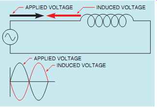
FIG. 4 The applied voltage and induced voltage are 180° out of phase
with each other.
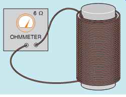
FIG. 5 Measuring the resistance of a coil.
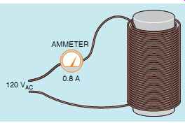
FIG. 6 Measuring circuit current with an ammeter.
COMPUTING THE INDUCED VOLTAGE
The amount of induced voltage in an inductor can be computed if the resistance of the wire in the coil and the amount of circuit current are known. For example, assume that an ohmmeter is used to measure the actual amount of resistance in a coil, and the coil is found to contain 6 O of wire resistance (FIG. 5).
Now assume that the coil is connected to a 120-V AC circuit and an ammeter measures a current flow of 0.8 A (FIG. 6). Ohm's law can now be used to determine the amount of voltage necessary to push 0.8 A of current through 6 Ohm of resistance.
E = I x R
E = 0.8 x 6
E = 4.8V
Since only 4.8 V is needed to push the current through the wire resistance of the inductor, the remainder of the 120 V is used to overcome the coil's induced voltage of 119.9 V (√[120^2 - 4.8^2] = 119:9V). Refer to vectors in Section 13.
INDUCTIVE REACTANCE
Notice that the induced voltage is able to limit the flow of current through the circuit in a manner similar to resistance. This induced voltage is not resistance, but it can limit the flow of current just as resistance does. This current-limiting property of the inductor is called reactance and is symbolized by the letter X. This reactance is caused by inductance, so it is called inductive reactance and is symbolized by XL, pronounced "X sub L." Inductive reactance is measured in ohms just as resistance is and can be computed when the values of inductance and frequency are known. The following formula can be used to find inductive reactance.
XL = 2πFL
where:
XL = inductive reactance
2 = a constant
pi or π = 3.1416
F = frequency in hertz (Hz)
L = inductance in henrys (H)
Inductive reactance is an induced voltage and is, therefore, proportional to the three factors that determine induced voltage:
1. The number of turns of wire
2. The strength of the magnetic field
3. The speed of the cutting action (relative motion between the inductor and the magnetic lines of flux)
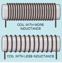
FIG. 7 Coils with turns closer together produce more inductance than
coils with turns far apart.
The number of turns of wire and strength of the magnetic field are determined by the physical construction of the inductor. Factors such as the size of wire used, the number of turns, how close the turns are to each other, and the type of core material determine the amount of inductance (in henrys, H) of the coil (FIG. 7). The speed of the cutting action is proportional to the frequency (Hz). An increase of frequency will cause the magnetic lines of flux to cut the conductors at a faster rate, and thus will produce a higher induced volt age or more inductive reactance.

FIG. 9 Schematic symbols for inductors.
SCHEMATIC SYMBOLS
The schematic symbol used to represent an inductor depicts a coil of wire. Several symbols for inductors are shown in FIG. 9. The symbols shown with the two parallel lines represent iron core inductors, and the symbols without the parallel lines represent air core inductors.
INDUCTORS CONNECTED IN SERIES
When inductors are connected in series (FIG. 10), the total inductance of the circuit (LT) equals the sum of the inductances of all the inductors.
LT = L1 + L2 + L3
The total inductive reactance (XLT) of inductors connected in series equals the sum of the inductive reactances for all the inductors.
XLT = XL1 + XL2 + XL3
INDUCTORS CONNECTED IN PARALLEL
When inductors are connected in parallel (FIG. 11), the total inductance can be found in a similar manner to finding the total resistance of a parallel circuit. The reciprocal of the total inductance is equal to the sum of the reciprocals of all the inductors.

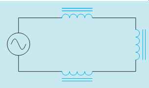
FIG. 10 Inductors connected in series.
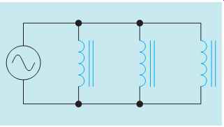
FIG. 11 Inductors connected in parallel.
The product over sum formula can be used also to find the total inductance of parallel inductors.
LT = L1 x L2/L1 + L2
If the values of all the inductors are the same, total inductance can be found by dividing the inductance of one inductor by the total number of inductors.
LT = L/N
Similar formulas can be used to find the total inductive reactance of inductors connected in parallel.
1/XLT = 1/XL1 + 1/XL2 + 1/XL3

VOLTAGE AND CURRENT RELATIONSHIPS IN AN INDUCTIVE CIRCUIT
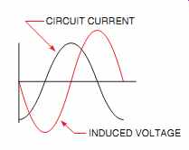
FIG. 12 Induced voltage is proportional to the rate of change of
current.
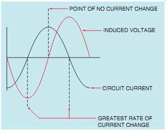
FIG. 13 No voltage is induced when the current does not change.
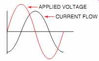
FIG. 14 The current lags the applied voltage by 90°.
In Section 11, it was discussed that when current flows through a pure resistive circuit, the current and voltage are in phase with each other. In a pure inductive circuit, the current lags the voltage by 90°. At first this may seem to be an impossible condition until the relationship of applied voltage and induced voltage is considered. How the current and applied voltage can become 90° out of phase with each other can best be explained by comparing the relationship of the current and induced voltage (FIG. 12). Recall that the induced voltage is proportional to the rate of change of the current (speed of cutting action). At the beginning of the waveform, the current is shown at its maximum value in the negative direction. At this time, the current is not changing, so induced voltage is zero. As the current begins to decrease in value, the magnetic field produced by the flow of current decreases or collapses and begins to induce a voltage into the coil as it cuts through the conductors (FIG. 13).
The greatest rate of current change occurs when the current passes from negative, through zero, and begins to increase in the positive direction (FIG. 13). Since the current is changing at the greatest rate, the induced voltage is maximum.
As current approaches its peak value in the positive direction, the rate of change decreases, causing a decrease in the induced voltage. The induced volt age will again be zero when the current reaches its peak value and the magnetic field stops expanding.
It can be seen that the current flowing through the inductor is leading the induced voltage by 90°.
Since the induced voltage is 180° out of phase with the applied voltage, the current will lag the applied voltage by 90° (FIG. 14).
POWER IN AN INDUCTIVE CIRCUIT
In a pure resistive circuit, the true power, or watts, is equal to the product of the voltage and current.
In a pure inductive circuit, however, no true power, or watts, is produced. Recall that voltage and cur rent must both be either positive or negative before true power can be produced. Since the voltage and current are 90° out of phase with each other in a pure inductive circuit, the current and voltage will be at different polarities 50% of the time and at the same polarity 50% of the time. During the period of time that the current and voltage have the same polarity, power is being given to the circuit in the form of creating a magnetic field. When the current and voltage are opposite in polarity, power is being given back to the circuit as the magnetic field collapses and induces a voltage back into the circuit.
Since power is stored in the form of a magnetic field and then given back, no power is used by the inductor. Any power used in an inductor is caused by losses such as the resistance of the wire used to construct the inductor, generally referred to as I^2 R losses, eddy current losses, and hysteresis losses.
FIG. 15 Voltage and current relationships during different parts of a cycle.
The current and voltage waveform in FIG. 15 has been divided into four sections:
A, B, C, and D. During the first time period, indicated by A, the current is negative and the voltage is positive. During this period, energy is being given to the circuit as the magnetic field collapses. During the second time period, section B, both the voltage and current are positive. Power is being used to produce the magnetic field. In the third time period, C, the current is positive and the voltage is negative. Power is again being given back to the circuit as the field collapses. During the fourth time period, D, both the voltage and current are negative. Power is again being used to produce the magnetic field. If the amount of power used to produce the magnetic field is subtracted from the power given back, the result will be zero.
REACTIVE POWER
Although essentially no true power is being used, except by previously mentioned losses, an electrical measurement called VARs is used to measure the reactive power in a pure inductive circuit. VARs is an abbreviation for volt-amps-reactive. VARs can be computed like watts except that inductive values are substituted for resistive values in the formulas.
VARs is equal to the amount of current flowing through an inductive circuit times the voltage applied to the inductive part of the circuit. Several formulas for computing VARs are
VARs = EL x IL
VARs = E^2 L XL
VARs = I^2 L x XL
where
EL = voltage applied to an inductor
IL = current flow through an inductor
XL = inductive reactance
Q OF AN INDUCTOR
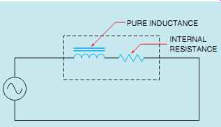
FIG. 16 Inductors contain internal resistance.
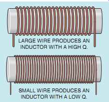
FIG. 17 The Q of an inductor is a ratio of inductive reactance as
compared with resistance. The letter Q stands for quality.
So far in this Section, it has been generally assumed that an inductor has no resistance and that inductive reactance is the only current-limiting factor. In reality, that is not true. Since inductors are actually coils of wire, they all contain some amount of internal resistance. Inductors actually appear to be a coil connected in series with some amount of resistance (FIG. 16). The amount of resistance compared with the inductive reactance determines the Q of the coil. The letter Q stands for quality.
Inductors that have a higher ratio of inductive reactance to resistance are considered to be inductors of higher quality. An inductor constructed with a large wire will have a low wire resistance and, therefore, a higher Q (FIG. 17). Inductors constructed with many turns of small wire have a much higher resistance, and, therefore, a lower Q.
To determine the Q of an inductor, divide the inductive reactance by the resistance.
Q = XL/R
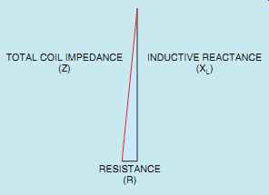
FIG. 18 Coil impedance is a combination of wire resistance and inductive
reactance.
Although inductors have some amount of resistance, inductors that have a Q of 10 or greater are generally considered to be pure inductors. Once the ratio of inductive reactance becomes 10 times as great as resistance, the amount of resistance is considered negligible. For example, assume an inductor has an inductive reactance of 100 Ohm and a wire resistance of 10 Ohm. The inductive reactive component in the circuit is 90° out of phase with the resistive component. This relationship produces a right triangle (FIG. 18). The total current limiting effect of the inductor is a combination of the inductive reactance and resistance. This total current-limiting effect is called impedance and is symbolized by the letter Z. The impedance of the circuit is represented by the hypotenuse of the right triangle formed by the inductive reactance and the resistance. To compute the value of impedance for the coil, the inductive reactance and resistance must be added. Since these two components form the legs of a right triangle and the impedance forms the hypotenuse, vector addition must be employed.

Notice that the value of total impedance for the inductor is only 0.5 O greater than the value of inductive reactance.
SUMMARY
• Induced voltage is proportional to the rate of change of current.
• Induced voltage is always opposite in polarity to the applied voltage.
• Inductive reactance is a counter voltage that limits the flow of current, as does resistance.
• Inductive reactance is measured in ohms.
• Inductive reactance is proportional to the inductance of the coil and the frequency of the line.
• Inductive reactance is symbolized by XL.
• Inductance is measured in henrys (H) and is symbolized by the letter L.
• When inductors are connected in series, the total inductance is equal to the sum of all the inductors.
• When inductors are connected in parallel, the reciprocal of the total inductance is equal to the sum of the reciprocals of all the inductors.
• The current lags the applied voltage by 90° in a pure inductive circuit.
• All inductors contain some amount of resistance.
• The Q of an inductor is the ratio of the inductive reactance to the resistance.
• Inductors with a Q of 10 are generally considered to be "pure" inductors.
• Pure inductive circuits contain no true power, or watts.
• Reactive power is measured in VARs.
• VARs is an abbreviation for volt-amps-reactive.
QUIZ
1. How many degrees are the current and voltage out of phase with each other in a pure resistive circuit?
2. How many degrees are the current and voltage out of phase with each other in a pure inductive circuit?
3. To what is inductive reactance proportional?
4. Four inductors, each having an inductance of 0.6 H, are connected in series. What is the total inductance of the circuit?
5. Three inductors are connected in parallel. Inductor 1 has an inductance of 0.06 H; inductor 2 has an inductance of 0.05 H; and inductor 3 has an inductance of 0.1H.What is the total inductance of this circuit?
6. If the three inductors in question 5 were connected in series, what would be the inductive reactance of the circuit? Assume the inductors are connected to a 60-Hz line.
7. An inductor is connected to a 240-V, 1000-Hz line. The circuit current is 0.6 A. What is the inductance of the inductor?
8. An inductor with an inductance of 3.6 H is connected to a 480-V, 60-Hz line. How much current will flow in this circuit?
9. If the frequency in question 8 is reduced to 50 Hz, how much current will flow in the circuit?
10. An inductor has an inductive reactance of 250 O when connected to a 60-Hz line. What will be the inductive reactance if the inductor is connected to a 400-Hz line?
REAL-WORLD APPLICATIONS
1. You are working as an electrician installing fluorescent lights. You notice that the lights were made in Europe and that the ballasts are rated for operation on a 50-Hz system. Will these ballasts be harmed by over current if they are connected to 60 Hz? If there is a problem with these lights, what will be the most likely cause of the trouble?
2. You have the task of ordering a replacement inductor for one that has become defective. The information on the nameplate has been painted over and cannot be read. The machine that contains the inductor operates on 480 V at a frequency of 60 Hz. Another machine has an identical inductor in it, but its nameplate has been painted over also. A clamp-on ammeter indicates a current of 18 A, and a voltmeter indicates a voltage drop of 324 V across the inductor in the machine that is still in operation. After turning off the power and locking out the panel, you disconnect the inductor in the operating machine and measure a wire resistance of 1.2 Ohm with an ohmmeter. Using the identical inductor in the operating machine as an example, what inductance value should you order, and what would be the minimum VAR rating of the inductor? Should you be concerned with the amount of wire resistance in the inductor when ordering? Explain your answer.