AMAZON multi-meters discounts AMAZON oscilloscope discounts
Cont. from part a
Solid-State Relays
Operation
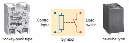
Ill.8 Typical solid-state relay (SSR). Control input; Symbol Ice-cube
type; Hockey-puck type Load switch
A solid-state relay (SSR) is an electronic switch that, unlike an electromechanical relay, contains no moving parts. Although EMRs and solid-state relays are designed to perform similar functions, each accomplishes the final results in different ways. Unlike electromechanical relays, SSRs don’t have actual coils and contacts. Instead, they use semiconductor switching devices such as bipolar transistors, MOSFETs, silicon-controlled rectifiers (SCRs), or triacs mounted on a printed circuit board. All SSRs are constructed to operate as two separate sections: input and output. The input side receives a voltage signal from the control circuit and the output side switches the load.
SSRs are manufactured in a variety of configurations that include both "hockey-puck" and "ice-cube" types (Ill.8). Most often a square or rectangle will be used on the schematic to represent the relay. The internal circuitry won’t be shown, and only the input and output connections to the box will be given.
Like electromechanical relays, solid-state relays provide electrical isolation between the input control circuit and the switched load circuit. A common method used to provide isolation is to have the input section illuminate a light-emitting diode (LED) that activates a photodetector device connected to the output section. The photodetector device triggers the output side, actuating the load. Relays that use this method of coupling the two circuits are said to be optoisolated.
Solid-state relays are constructed with different main switching devices depending on the type of load being switched. If the relay is designed to control an AC load, a triac is commonly used as the main switching semiconductor. A simplified diagram of an optically coupled solid-state relay used to switch an AC load is shown in Ill. 9. The operation of the circuit can be summarized as follows.
• A current flow is established through the LED connected to the input when conditions call for the relay to be actuated.
• The LED conducts and shines light on the phototransistor.
• The phototransistor conducts switching on the triac and AC power to the load.
• The output is isolated from the input by the simple LED and phototransistor arrangement.
• Since a light beam is used as the control medium, no voltage spikes or electrical noise produced on the load side of the relay can be transmitted to the control side of the relay.
Solid-state relays intended for use with DC loads have a power transistor rather than a triac connected to the load circuit as shown in Ill.10. The operation of the circuit can be summarized as follows:
• When the input voltage turns the LED on, the photodetector connected to the base of the transistor turns the transistor on, allowing current flow to the load.
• The LED section of the relay acts like the coil of the electromechanical relay and requires a DC voltage for its operation.
• The transistor section of the optocoupler inside the SSR is equivalent to the contacts in a relay.
• Because solid-state relays have no moving parts, their switching response time is many times faster than that of electromechanical relays. For this reason, when loads are to be switched continually and quickly, the SSR is the relay of choice.
Specifications
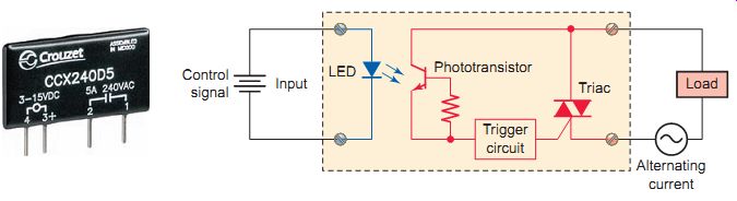
Ill.9 Optically coupled SSR used for AC loads. Alternating current; Control
signal; Input; LED Phototransistor; Triac
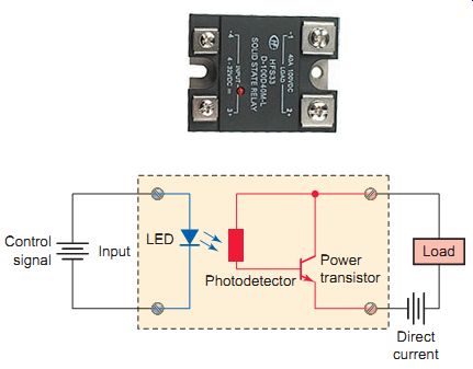
Ill. 10 Optically coupled SSR used for DC loads. Control signal; Power
transistor; Photodetector Input LED Direct current
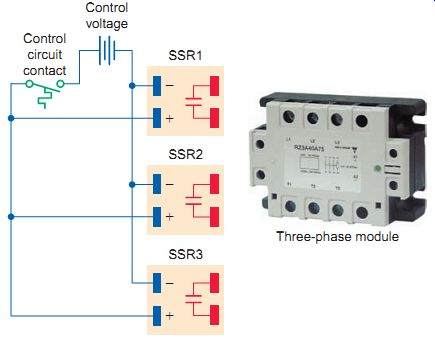
Ill. 11 Multiple-pole solid-state relay connections.
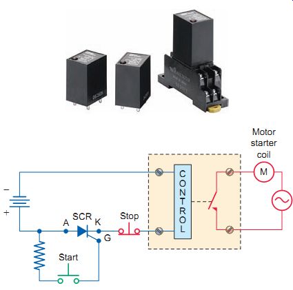
Ill. 12 Three-wire control utilizing a solid-state relay and an SCR.
Applying the specified amount of pickup voltage activates the SSR input control circuit of an SSR. Most SSRs have a variable input voltage range, such as 5 V DC to 24 V DC. This voltage range makes the SSR compatible with a variety of electronic input devices. Output voltage ratings range from 5 V DC up to 480 V AC. Although most SSRs are designed for a rated output current of under 10 A, relays mounted on heat sinks are capable of controlling up to 40 A.
The majority of SSRs are single-pole devices, as multi-pole relays pose a greater power dissipation problem.
When multiple poles are required, a multipole solid state module can be used. Another solution is to wire several SSR control circuits in parallel, as illustrated in Ill.11, to provide the equivalent function as a multipole electromagnetic relay. In this application, three single-pole solid-state relays are used to switch current to a three-phase load. The input section may receive a signal from a variety of sources such as device contacts or sensor signals. When the control circuit contact closes, all three relays actuate to complete the current path to the load.
The standard single-pole SSR configuration works fine with two-wire control; however, when it becomes necessary for it to be used in a three-wire control scheme, the problem of the holding circuit arises. An additional relay can be wired in parallel to the SSR to act as the holding contact. Another solution is to use a DC control circuit with a silicon-controlled rectifier (SCR) for latching the load. Ill.12 shows a three-wire motor control circuit utilizing a solid-state relay and an SCR. The operation of the circuit can be summarized as follows.
• The SCR won’t allow current flow from anode (A) to cathode (K) until current is applied to the gate (G).
• When the start push button is pressed, current flows through the gate, which triggers the anode-to-cathode section of the SCR and relay control circuit into conduction.
• The SCR remains latched on after the start push button is released, and the circuit must be opened to stop the anode-to-cathode current flow. This is accomplished by pressing the stop push button. Switching Methods SSRs operate with several different switching methods.
The type of load is an important factor in the selection of the switching method.
• Zero-switching relay. A zero-switching relay is designed to turn on an AC load when the control voltage is applied and the voltage at the load passes through zero. The relay turns off the load when the control voltage is removed and the current in the load crosses zero. This allows resistive loads such as lamp filaments to last longer because they are not subjected to high-voltage transients from switching AC voltage and current when the sine wave is at a peak. Ill.13 shows a simplified diagram of a zero-switching SSR.
• Peak-switching relay. A peak-switching relay is an SSR that turns the load on when the control volt age is present and the voltage at the load is at its peak. The relay turns off when the control voltage is removed and the current in the load crosses zero.
Peak switching is preferred when the output circuit's mostly inductive or capacitive and the voltage and current are approximately 90 degrees out of phase.
In this case, when the voltage is at or near its peak value, the current will be at or near its zero value.
• Instant-on relay. Instant-on relays are typically specified when the controlled load is a combination of resistance and reactance. In this case the voltage and current phase angle vary, so there is no advantage to disconnecting the load at any specific time on the sine wave.
Solid-state relays have several advantages over electro mechanical types:
• The SSR is more reliable and has a longer life because it has no moving parts.
• It’s compatible with transistor and IC circuitry and does not generate as much electromagnetic interference.
• The SSR is more resistant to shock and vibration, has a much faster response time, and does not exhibit contact bounce.
Like every device, SSRs do have some disadvantages.
The SSR contains semiconductors that are susceptible to damage from voltage and current spikes. In addition, unlike the EMR contacts, the SSR switching semiconductor has a significant on-state resistance and off-state leak age current. As a result, compared to electromechanical relays they produce more heat during normal operation, and if they are not properly cooled, this prolonged heat can reduce the life of the relay.
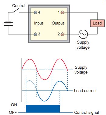
Ill.13 Zero-switching SSR.
QUIZ:
1. What is the fundamental difference between an electromechanical and a solid-state relay?
2. A common method employed in SSRs to provide isolation between input and output circuits is opto isolation. Give a brief explanation of how this works.
3. State the type of SSR main switching semiconductor used to control
a. AC loads.
b. DC loads.
4. A given SSR has an input control voltage rating of 3 to 32 V DC. What does this imply as far as actuation of the relay is concerned?
5. Why are the majority of solid-state relays constructed as single-pole devices?
6. List three common switching modes for SSRs.
7. Explain the advantage gained by using a zero switching relay to control a resistive load.
8. List three advantages SSRs have compared to electromechanical types.
9. Why do solid-state relays generate more heat during normal operation than electromechanical types?
Cont. to part c