AMAZON multi-meters discounts AMAZON oscilloscope discounts
GOALS:
1. Compare electromagnetic, solid-state, timing and latching relays in terms of construction and operation.
2. Recognize relay symbols used on schematic diagrams.
3. Identify different types of relay applications.
4. Explain how relays are rated.
5. Describe the operation of on-delay and off-delay timer relays.
6. Discuss the use of relays as control elements in motor circuits.
Many motor applications in industry and in process control require relays as critical control elements. Relays are used primarily as switching devices in a circuit. This section explains the operation of different types of relays and the advantages and limitations of each type.
Relay specifications are also presented to show how to determine the correct relay type for different applications.
Electromechanical Control Relays
Relay Operation
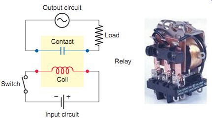
Ill. 1 Electromechanical control relay. Input circuit; Output circuit;
Contact
An electromechanical relay (EMR) is best defined as a switch that's operated by an electromagnet. The relay turns a load circuit on or off by energizing an electromagnet, which opens or closes contacts connected in series with a load. A relay is made up of two circuits: the coil input or control circuit and the contact output or load circuit, as illustrated in Ill.1. Relays are used to control small loads of 15 A or less. In motor circuits electromechanical relays are often used to control coils in motor contactors and starters. Other applications include switching of solenoids, pilot lights, audible alarms and small motors ( 1/8 hp or less).
Operation of a relay is very similar to that of a contactor. The main difference between a control relay and a contactor is the size and number of contacts. Control relay contacts are relatively small because they need to handle only the small currents used in control circuits. The small size of control relay contacts allows control relays to contain multiple isolated contacts.
A relay will usually have only one coil, but it may have any number of different contacts. Electromechanical relays contain both stationary and moving contacts, as illustrated in Ill. 2. The moving contacts are attached to the armature. Contacts are referred to as normally open (NO) and normally closed (NC). When the coil is energized, it produces an electromagnetic field. Action of this field, in turn, causes the armature to move, closing the NO contacts and opening the NC contacts. The distance that the plunger moves is generally short-about ¼ inch or less. A letter is used in most diagrams to designate the coil. The letter M frequently indicates a motor starter, while CR is used for control relays. The associated contacts will have the same identifying letters.
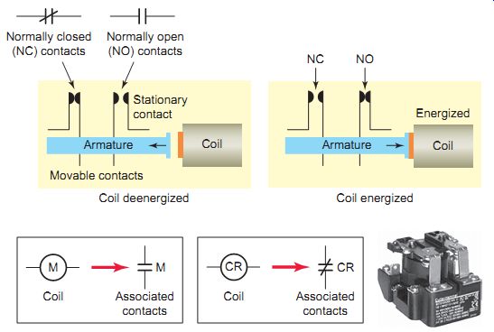
Ill. 2 Relay coil and contacts. Normally closed (NC) contacts; Normally
open (NO) contacts; Movable contacts Coil deenergized Coil energized;
Associated contacts
Normally open contacts are open when no current flows through the coil but closed as soon as the coil conducts a current or is energized. Normally closed contacts are closed when the coil is deenergized and open when the coil is energized. Each contact is normally drawn as it would appear with the coil deenergized. Some control relays have some provision for changing contacts from normally open to normally closed types, or vice versa. The provisions range from a simple flip-over contact to removing the contacts and relocating with spring location changes.
Relays are used to control several switching operations by a single, separate current. One relay coil/armature assembly may be used to actuate more than one set of contacts. Those contacts may be normally open, normally closed, or any combination of the two. A simple example of this type of application is the relay control with two pilot lights illustrated in Ill. 3. The operation of the circuit can be summarized as follows:
• With the switch open, coil CR1 is deenergized.
• The circuit to the green pilot light is completed through normally closed contact CR1-2, so this light will be on.
• At the same time, the circuit to the red pilot light is opened through normally open contact CR1-1, so this light will be off.
• With the switch closed, the coil is energized.
• The normally open contact CR1-1 closes to switch the red pilot light on.
• At the same time, the normally closed CR1-2 opens to switch the green pilot light off.
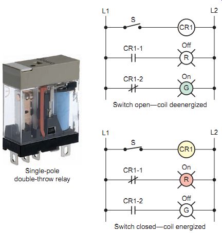
Ill.3 Relay switching operation. Single-pole double-throw relay; Switch
open-coil deenergized; Switch closed-coil energized
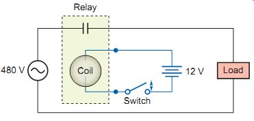
Ill.4 Relay used to control a high-voltage circuit with a low-voltage
circuit.
Relay Applications
Relays are extremely useful when we need to control a large amount of current and /or voltage with a small electrical signal. The relay coil, which produces the magnetic field, may consume only a fraction of a watt of power, while the contacts closed or opened by that magnetic field may be able to conduct hundreds of times that amount of power to a load.
You can use a relay to control a high-voltage load circuit with a low-voltage control circuit as illustrated in the circuit of Ill.4. This is possible because the coil and contacts of the relay are electrically insulated from each other. The relay's coil is energized by the low- voltage (12-V) source, while the contact interrupts the high-voltage (480-V) circuit. Closing and opening the switch energizes and de-energizes the coil. This, in turn, closes and opens the contacts to switch the load on and off.
You can also use a relay to control a high-current load circuit with a low-current control circuit. This is possible because the current that can be handled by the contacts can be much greater than what is required to operate the relay coil. Relay coils are capable of being controlled by low-current signals from integrated circuits and transistors, as illustrated in Ill. 5. The operation of the circuit can be summarized as follows.
• The electronic control signal switches the transistor on or off, which in turn causes the relay coil to energize or deenergize.
• The current in the transistor control circuit and relay coil is quite small in comparison to that of the solenoid load.
• Transistors and integrated circuits (ICs, or chips) must be protected from the brief high-voltage spike produced when the relay coil is switched off.
• In this circuit a diode is connected across the relay coil to provide this protection.
• Note that the diode is connected backward so that it will normally not conduct. Conduction occurs only when the relay coil is switched off; at this moment current tries to continue flowing through the coil and it’s harmlessly diverted through the diode.
Relay Styles and Specifications
Control relays are available in a variety of styles and types. One popular type is the general-purpose "ice cube" relay, so named because of its size and shape and the clear plastic enclosure surrounding the contacts. Although the contacts are non-replaceable, this relay is designed to plug into a socket, making replacement fast and simple in the event of failure. An eight-pin plug-in-style ice cube relay is shown in Ill.6. This relay contains two separate single-pole double-throw contacts. Because the relay plugs into a socket, the wiring is connected to the socket, not the relay. The numbering on the socket base designates a terminal with the corresponding pin position. Care must be taken not to confuse the base numbers with the wire reference numbers used to label control wires.
Relay options that aid in troubleshooting are also available. An on/off indicator is installed to indicate the state (energized or deenergized) of the relay coil. A manual override button, mechanically connected to the contact assembly, may be used to move the contacts into their energized position for testing purposes. Use caution when exercising this feature, as the circuit controlling the coil is bypassed and loads may be energized or deenergized without warning.
Like contactors, relay coils and contacts have separate ratings. Relay coils are usually rated for type of operating current (DC or AC), normal operating voltage or current, permissible coil voltage variation (pickup and dropout), resistance, and power. Coil voltages of 12 V DC, 24 V DC, 24 V AC, and 120 V AC are most common. Sensitive relay coils that require as little as 4 mA at 5 V DC are used in relay circuits operated by transistor or integrated circuit chips.
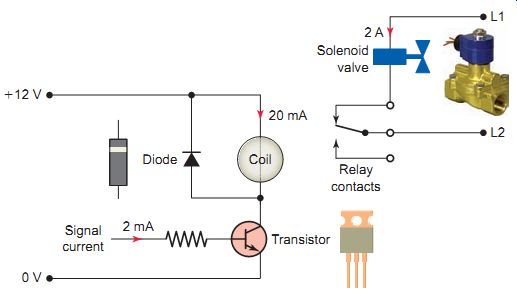
Ill.5 Using a relay to control a high-current load circuit with a low-current
control circuit.
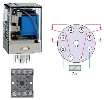
Ill.6 Plug-in style ice cube relay.
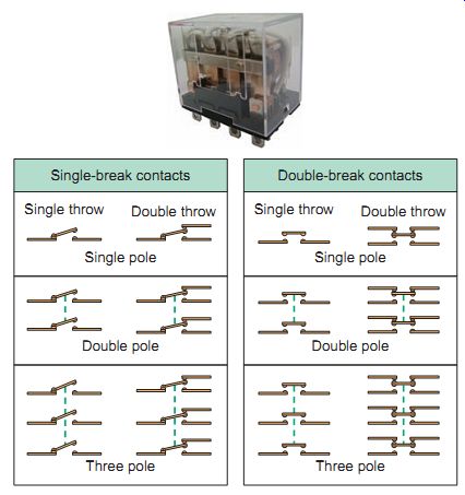
Ill.7 Common relay contact switching arrangements
Relays are available in a wide range of switching configurations. Ill.7 illustrates common relay contact switching arrangements. Like switch contacts, relay contacts are classified by their number of poles, throws, and breaks.
• The number of poles indicates the number of completely isolated circuits that a relay contact can switch. The single-pole contact can conduct current through only one circuit at a time while a double pole contact can conduct current through two circuits simultaneously.
• A throw is the number of closed contact positions per pole (single or double). The single-throw con tact can control current in only one circuit while the double-throw contact can control two circuits.
• The term break designates the number of points in a set of contacts where the current will be interrupted during opening of the contacts. All relay contacts are constructed as single break or double break.
Single-break contacts have lower current ratings because they break the current at only one point.
In general, relay contact ratings are rated in terms of the maximum amount of current the contacts are capable of handling at a specified voltage level and type (AC or DC). Current ratings specified may include:
• Inrush or make-contact capacity
• Normal or continuous carrying capacity
• Opening or break capacity
The load-carrying capacity of contacts is normally given as a current value for a resistive load. Lamp filaments are resistive, but change in value by a large factor from their cold state to their operating state resistance. This effect is so great that the inrush current can be expected to be 10 to 15 times greater than the steady-state value. Normal practice is to de-rate contacts to 20 percent of their resistive load capabilities for a lamp load. Inductive loads, such as transformers, act as energy storage devices and can cause excessive contact arcing when the relay breaks the circuit. For inductive type loads contacts are normally derated to 50 percent of their resistive load capacity.
Relay contacts often have two ratings: AC and DC. These ratings indicate how much power can be switched through the contacts. One way to determine the maximum power capacity of relay contacts is to multiply the rated volts times the rated amperes. This will give you the total watts a relay can switch. For instance, a 5-A relay rated at 125 V AC can also switch 2.5 A at 250 V AC. Similarly, a 5-A relay rated at 24 V DC can switch 2.5 A at 48 V DC, or even 10 A at 12 V DC.
QUIZ:
1. What exactly is an electromechanical control relay?
2. A relay involves two circuits. Name the two circuits and explain how they interact with each other.
3. Compare control relays with contactors.
4. Describe the switching action of normally open and normally closed relay contacts.
5. Outline three basic ways in which control relays are put to use in electric and electronic circuits.
6. An eight-pin octal-base ice-cube-style relay is to be wired into a control circuit that requires a set of NO and NC contacts electrically isolated from one another. State the number of the pin connections you would use for each contact.
7. How many breaks can relay contacts have?
8. What does SPDT stand for?
9. List three types of current ratings that may be specified for relay contacts.
10. The load-carrying capacity of contacts is normally given as a current value for a resistive load. Name two types of load devices that require this value to be derated.
11. How many amperes of current can a relay contact rated for 10 A at 250 V AC safely switch at 125 V AC?
Cont. to part b