AMAZON multi-meters discounts AMAZON oscilloscope discounts
Cont. from part b
Timing Relays
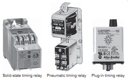
Ill.14 Timing relays. Solid-state timing relay Plug-in timing relay Pneumatic
timing relay
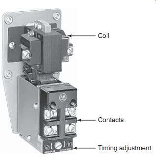
Ill.16 Pneumatic timer. Coil; Contacts; Timing adjustment
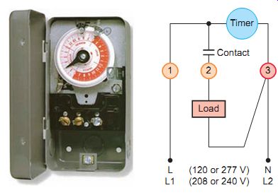
Ill.15 Synchronous clock timer.
Timing relays are a variation of the standard instantaneous control relay in which a fixed or adjustable time delay occurs after a change in the control signal before the switching action occurs. Typical types of timing relays are shown in Ill.14. Timers allow a multitude of operations in a control circuit to be automatically started and stopped at different time intervals. The use of timers can eliminate the labor-intensive process of trying to manually control each step of a process.
Motor-Driven Timers
Timer functions include timing a cycle of operation, delaying the starting or stopping of an operation, and con trolling time intervals within an operation. Motor-driven timers are used to time a cycle of operations. Synchro nous clock types, such as shown in Ill.15, use a small electric clock motor driven from the AC power line to maintain sync with standard time. A mechanical connection to the clock mechanism controls the contacts. The operation of the device can be summarized as follows.
• The motor turns the mechanism and actuates normally open or normally closed contacts.
• Adjustable on/off tabs set along the clock's timing wheel trip the contact open or closed.
• The timer motor is supplied with continuous power.
If power is lost, the timing will be delayed by an amount of time the power was off, and the correct time must be manually reset.
• These types of timers are best suited for applications such as lighting and water sprinkler control where precise timing isn't critical.
Dashpot Timers
Dashpot timers manage their timing function by control ling fluid flow or airflow through a small orifice. The pneumatic (air) timing relay shown in Ill.16 uses an air-bellows system to achieve its timing cycle. The operation of the device can be summarized as follows.
• The bellows design allows air to enter through an orifice at a predetermined rate to provide time-delay increments.
• As soon as the coil is energized or deenergized, the timing process begins and the rate of airflow deter mines the length of the time delay.
• Smaller orifice openings restrict the flow rate, resulting in longer time delays.
• Pneumatic timers have relatively small adjustable range settings. The timing range for the timer shown is adjustable from 0.05 to 180 seconds with an accuracy of approximately +10 percent.
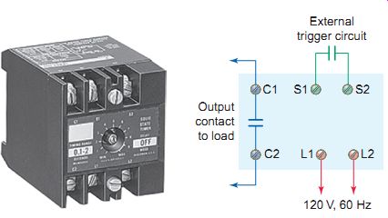
Ill.17 Solid-state timing relay connections. Output contact to load;
External trigger circuit
Solid-State Timing Relays
Solid-state timing relays use electronic circuitry to provide their timing functions. The two broad categories of solid state timers are analog and digital. Different methods are used to control the time-delay period. Some use a resistor/ capacitor ( RC ) charge and discharge circuit to obtain the time base, while others use quartz clocks as the time base.
These electronics-based timers are much more accurate than their dashpot counterparts and can control timing functions ranging from a fraction of a second to hundreds of hours. In order to maintain their timing operations, solid-state timers are normally constantly powered. Some are equipped with batteries or internal memory to retain their settings during power failures.
The timing functions of dashpot timers are initiated when the electromagnetic coil is energized or deenergized.
In comparison, solid-state timing functions are initiated when the electronic circuit of the timer is energized or a triggering signal is received or removed. Electronic timers are available in a variety of rated input operating voltages.
Ill.17 shows a typical solid-state timing relay. The operation of the device can be summarized as follows.
• Connections provided include timed contacts (C1, C2), voltage input (L1, L2), and external trigger switch (S1, S2).
• A timing-delay period of from 0.1 to 2 seconds is set by the adjustment of an internal potentiometer located on the front panel of the timer.
• The timer is energized continuously, and timing is initiated when the external trigger circuit's closed.
• The timed contact is convertible to on-delay or off delay.
Timing Functions
There are four basic timing functions: on-delay, off-delay, one-shot, and recycle.
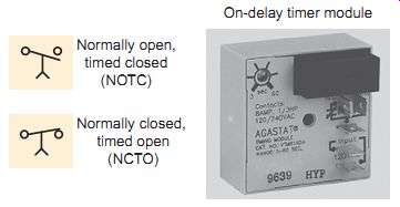
Ill.18 On-delay timer contacts. On-delay timer module; Normally open,
timed closed (NOTC); Normally closed, timed open (NCTO)
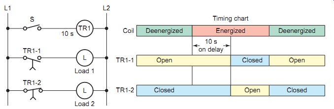
Ill.19 On-delay relay timer circuit.
ON-DELAY TIMER
The on-delay timer is sometimes referred to as DOE, which stands for delay on energize. The time delay of the contacts begins once the timer is switched on; hence the term on-delay timing. Ill.18 shows the NEMA symbols for the on-delay timer normally open (NO) and normally closed (NC) contacts. The operation of the timed contacts can be summarized as follows.
• Once initiated, DOE timed contacts change state after a set time period has passed.
• After that time has passed, all normally open timed contacts close and all normally closed contacts open.
• Once the timed contacts change state, they will remain in this position until the power is removed from the coil or electronic circuit.
The circuit shown in Ill.19 illustrates the timing function of an on-delay timing relay. In this example a simple dashpot timer with a time delay setting of 10 seconds can be assumed. The same operation applies to electronic timers that perform a similar function. The operation of the circuit can be summarized as follows.
• When the switch is closed, power is applied to the coil but the contacts are delayed from changing position.
• With the switch still closed, after the 10-second timing period the normally open contacts (TR1-1) close to energize load 1 and the normally closed contacts (TR1-2) open to deenergize load 2.
• If the switch is then opened, the coil de-energizes immediately, returning both timed contacts to their normal state, switching load 1 on and load 2 off.
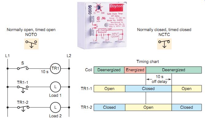
Ill.20 Off-delay relay timer. Normally open, timed open NOTO; Normally
closed, timed closed NCTC;
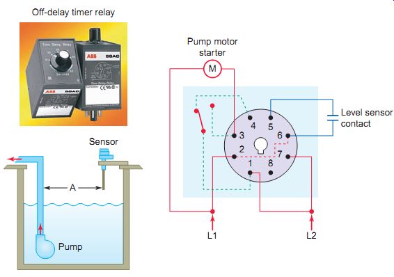
Ill.21 Off-delay timer automatic pumping circuit. Sensor; Off-delay timer
relay; Pump; Pump motor starter; Level sensor contact
OFF-DELAY TIMER
The off-delay timer is sometimes referred to as DODE, which stands for delay on deenergize. The operation of the off-delay timer is the exact opposite of that of the on-delay timer. When power is applied to the coil or electronic circuit, the timed contacts will change state immediately. When power is removed, however, there is a time delay before the timed contacts change to their normal deenergized positions. Ill.20 shows the standard NEMA symbols and illustrates the timing function of an off-delay timing relay.
Ill.21 shows the wiring diagram for the automatic pumping down of a sump using a level sensor switch and plug-in cube-type off-delay timer. A solid-state timing circuit drives an internal electromechanical relay within the timer. The operation of the circuit can be summarized as follows.
• When the level rises to point A, the level sensor contact closes to energize the relay timer coil and close the NO contacts to the pump motor starter.
• This immediately turns the pump on to initiate the pumping action.
• When the height of the vessel level decreases the sensor contacts open and timing begins.
• The pump continues to run and empty the tank for the length of the time-delay period.
• At time-out the relay coil de-energizes and the normally open relay contact reopens, turning the pump off.
• The timer has a built-in time adjustment potentiometer that's adjusted to empty the tank to a desired level before the pump shuts off.
ONE-SHOT TIMER
With a one-shot timer, momentary or continuous closure of the initiate circuit results in a single timed pulse being delivered to the output. The one-shot causes this action to happen only once, and then must be reinitiated if it’s to continue to operate. The circuit of Ill.22 illustrates the wiring and timing function of a typical one-shot timer. The operation of the circuit can be summarized as follows.
• Input voltage must be applied before and during timing.
• Upon momentary or maintained closure of the initiate button, the output load is energized.
• The load remains energized for the duration of the time-delay period and then is return to its normal deenergized state ready to be initiated for another cycle of operation.
• Opening or reclosing the initiate button during timing has no effect on the time delay. Reset occurs when the time delay is complete and the initiate button is open.
• If power is interrupted to a one-shot timer during the time-delay operation, the time delay is canceled.
When power is restored to the timer, the time-delay function won’t begin again until the one-shot has been reinitiated.
• One-shot timers don’t have dedicated contact symbols. Instead, the standard NO and NC contact symbols are used and referenced to the timer that controls them.
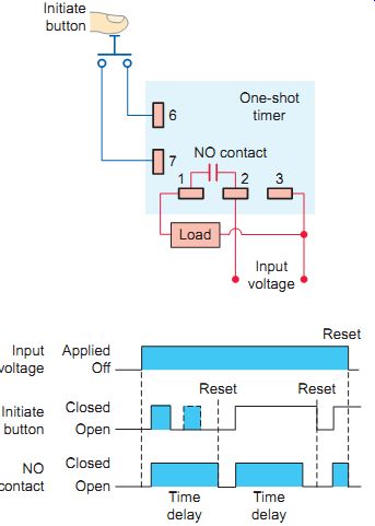
Ill.22 One-shot timer. Open NO contact Initiate button Input voltage
Applied Off Closed Open Closed
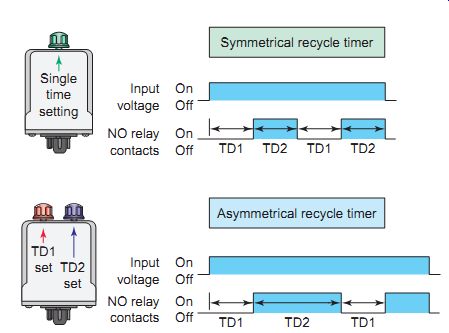
Ill.23 Recycle timers. Single time setting; Asymmetrical recycle timer;
Symmetrical recycle timer; TD1 TD2 TD1 TD2
RECYCLE TIMER
The contacts of a recycle timer alternate between the on and off states when the timer is initiated. Solid-state circuits within the device drive an internal electromagnetic relay. The operation of the recycle timers shown in Ill.23 can be summarized as follows.
• Upon application of input voltage, the first delay period (TD1) begins and the output remains deenergized, or off.
• At the end of the first delay, or off period, the relay coil will energize and the second delay (TD2), or on period, begins.
• When the second delay period ends, the relay de-energizes.
• This recycling sequence will continue until input voltage is removed.
• In some recycling timers the on time may be con figured for the first delay. Removing input voltage resets the output and time delays, and returns the sequence to the first delay.
• Recycle timers are available in two configurations: symmetrical and asymmetrical.
• In symmetrical timing, the on and off periods are equal. The length of the timing period is adjust able but the time between the on and off operations remains constant. Flashers are an example of sym metrical timing.
• Asymmetrical timers allow independent adjustments for the on and off periods. They come equipped with individual on and off time adjustment knobs and use standard NO and NC contact symbols referenced to the timer that controls them.
Multifunction and PLC Timers
MULTIFUNCTION TIMER
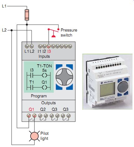
Ill.25 PLC programmed on-delay timer. Pressure switch
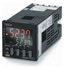
Ill.24 Multifunction digital timer.
The term multifunction timer refers to timers that perform more than one timing function. Multifunction timers are more versatile in that they can perform many different timing functions and therefore are more common. Ill.24 shows a multifunction digital timer that's capable of performing all of the basic timing functions.
PLC TIMERS
Programmable logic controllers (PLCs) can be programmed to operate like conventional timing relays.
The PLC timer instruction can be used to activate or deactivate a device after a preset interval of time. One advantage of the PLC timer is that its timer accuracy and repeatability are extremely high. The most common types of PLC timer instructions are the on-delay timer (TON), off-delay timer (TOF), and retentive timer on (RTO).
Ill.25 illustrates how an Allen-Bradley Pico programmable logic controller is wired and programmed to implement an on-delay timer function. This application calls for the pilot light to turn on any time the pres sure switch closes for a sustained period of 5 seconds or more. The procedure followed can be summarized as follows.
• The pressure switch is hard-wired to input I3 and the pilot light output to Q1 according to the wiring diagram.
• Next the ladder logic program is entered, using the front keypad and LCD display.
• When the pressure switch contacts close, the programmed timing coil T1 energizes, initiating the time-delay period.
• After 5 seconds have passed, programmed timer contact T1 closes to energize output relay coil Q1 and turn the pilot light on.
• Opening of the pressure switch contacts at any time resets the timed value to zero.
QUIZ:
1. In what way is a timing relay different from a standard control relay?
2. Explain how contacts are closed and opened in a synchronous clock timer.
3. What types of applications are synchronous clock timers best suited for?
4. Assume power is lost and later returned to a synchronous clock timer. In what way would this affect its operation?
5. Explain how timing is achieved in a dashpot timer.
6. Compare the manner in which the instantaneous and timed contacts of a dashpot timer operate.
7. Compare the accuracy and timing range of solid state and dashpot timers.
8. Dashpot timers rely on an electromagnetic coil to initiate their timing functions. How is this accomplished with solid-state relays?
9. List four basic types of timing functions.
10. State what the timer abbreviations DOE and DODE stand for.
11. Outline the switching operation of the NOTC and NCTO contacts of an on-delay timer.
12. Outline the switching operation of the NOTC and NCTO contacts of an off-delay timer.
13. The normally open contacts of a one-shot timer are used to control a solenoid valve. Explain what happens when the timing function is momentarily initiated.
14. Assume power is lost and later returned to a one-shot timer. In what way will this affect its operation?
15. Explain the switching operation of the timed contacts of a recycle timer.
16. Compare the manner in which the timed contacts of a symmetrical and an asymmetrical recycle timer can be set to operate.
17. To what general classification of timers do multi function timers belong?
18. List the three most common PLC timer instructions.
Cont. to part d