AMAZON multi-meters discounts AMAZON oscilloscope discounts
Goals:
1. Identify manually operated switches commonly found in motor control circuits and explain their operation.
2. Identify mechanically operated switches commonly found in motor control circuits and explain their operation.
3. Identify different types of sensors and explain how they detect and measure the presence of something.
4. Describe the operating characteristics of a relay, solenoid, solenoid valve, stepper motor, and brushless DC motor.
Control devices are components that govern the power delivered to an electrical load. Motor control systems make use of a wide variety of control devices. The motor control devices introduced in this section range from simple pushbutton switches to more complex solid-state sensors.
The terms and practical applications presented here illustrate how selection of a control device depends on the specific application.
Manually-Operated Switches
Primary and Pilot Control Devices
A control device is a component that governs the power delivered to an electrical load. All components used in motor control circuits may be classed as either primary control devices or pilot control devices. A primary control device , such as a motor contactor, starter, or controller, connects the load to the line. A pilot control device, such as a relay or switch contact, is used to activate the primary control device. Pilot-duty devices shouldn't be used to switch horsepower loads unless they are specifically rated to do so. Contacts selected for both primary and pilot control devices must be capable of handling the voltage and current to be switched. Ill. 1 shows a typical motor control circuit that includes both primary and pilot control devices. In the application shown, the closing of the toggle switch contact completes the circuit to energize contactor coil M. This in turn closes the contacts of the contactor to complete the main power circuit to the motor.
Toggle Switches
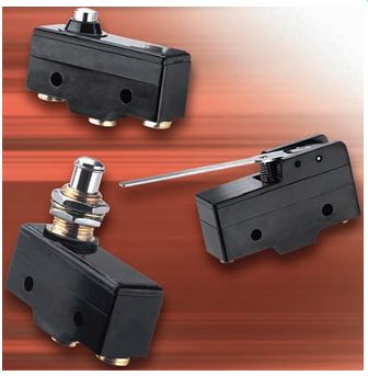
A manually operated switch is one that's controlled by hand. The toggle switches illustrated in Ill. 2 are examples of manually operated switches. A toggle switch uses a mechanical lever mechanism to implement a positive snap action for switching of electrical contacts. This type of switching or contact arrangement is specified by the appropriate abbreviation as follows:
- SPST-Single pole, single throw
- SPDT-Single pole, double throw
- DPST-Double pole, single throw
- DPDT-Double pole, double throw
Electrical ratings for switches are expressed in terms of the maximum interrupting voltage and current they can safely handle. AC and DC contact current ratings are not the same for a given switch. The AC current rating will be higher than its DC rating for an equivalent amount of volt age. The reason for this is that AC current is at zero level twice during each cycle, which reduces the likelihood of an electric arc forming across the contacts. Also, higher decaying voltages are generated in DC circuits that contain inductive type load devices. Switch voltage and cur rent ratings represent maximum values and may be used in circuits with voltages and currents below these levels but never above.
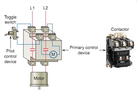
Ill. 1 Primary and pilot control devices.
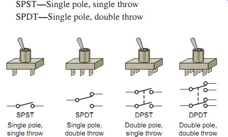
Ill. 2 Toggle switches.
Double pole, single throw Double pole, double throw Single pole, single throw Single pole, double throw DPST DPDT
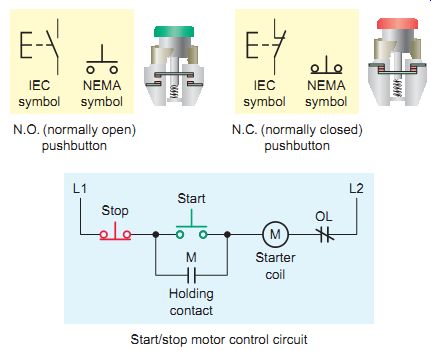
Ill. 3 Pushbutton symbols and switching action. N.O. (normally open)
pushbutton N.C. (normally closed) pushbutton; Start/stop motor control
circuit
Pushbutton Switches
Pushbutton switches are commonly used in motor control applications to start and stop motors, as well as to control and override process functions. A push button operates by pressing a button that opens or closes contacts. Ill. 3 shows commonly used types of pushbutton symbols and switching action. Abbreviations N.O. (normally open) and N.C. (normally closed) represent the state of the switch contacts when the switch isn't activated. The N.O. push button makes a circuit when it’s pressed and returns to its open position when the button is released. The N.C. push button opens the circuit when it’s pressed and returns to the closed position when the button is released.
With a break-make push button, the top section contacts are N.C. and the bottom section contacts are N.O. When the button is pressed, the bottom contacts are closed after the top contacts open. Ill. 4 shows a break make push button used in a jog-start-stop motor control circuit. The operation of the circuit can be summarized as follows:
• Pressing the start push button completes a circuit for the M coil, causing the motor to start, and the M contact holds in the M coil circuit.
• With the M coil deenergized and the jog push button then pressed, a circuit's completed for the M coil around the M contact. The M contact closes, but the holding circuit's incomplete, as the N.C. contact of the jog button is open.
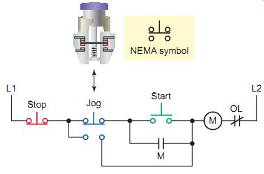
Ill. 4 Break-make push button and typical motor control circuit.
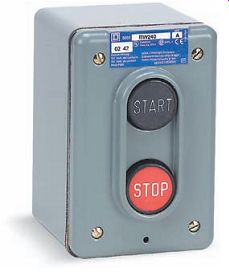
Ill. 5 Pushbutton station-NEMA Type1.
When you have one or more push buttons in a common enclosure, it’s referred to as a pushbutton station ( Ill. 5). Electrical enclosures are designed to protect their contents from troublesome operating environmental conditions such as dust, dirt, oil, water, corrosive materials, and extreme variations in temperature. The types of enclosures are standardized by the National Electrical Manufacturers Association (NEMA). NEMA enclosure types are selected according to the environment in which the equipment is installed. A partial listing of specific enclosure types is given below.
Nema Enclosure Types
Type Use Service Conditions
1. Indoor No unusual; 3. Outdoor Windblown dust, rain, sleet, and ice on enclosure 3R Outdoor Falling rain and ice on enclosure 4 Indoor/outdoor Windblown dust and rain, splashing water, hose-directed water, and ice on enclosure 4X Indoor/outdoor Corrosion, windblown dust and rain, splashing water, hose directed water, and ice on enclosure 6 Indoor/outdoor Occasional temporary submersion at a limited depth 6P Indoor/outdoor Prolonged submersion at a limited depth 7 Indoor locations classified as Class I, Groups A, B, C, or D, as defined in the NEC Withstand and contain an internal explosion sufficiently so an explosive gas-air mixture in the atmosphere isn't ignited 9 Indoor locations classified as Class II, Groups E or G, as defined in the NEC Dust 12 Indoor Dust, falling dirt, and dripping noncorrosive liquids 13 Indoor Dust, spraying water, oil, and noncorrosive coolant
Pushbutton assemblies are manufactured in both 30-mm NEMA and smaller 22-mm IEC types, as illustrated in Ill. 6. The size is related to the diameter of the circular hole the push button is mounted in-either 30 millimeters or 22 millimeters in diameter. Pushbutton assemblies basically consist of an operator legend plate and contact block.
Operator--The operator is the part of the pushbutton assembly that's pressed, pulled, or rotated to activate the push button's contacts. Operators come in many different colors, shapes, and sizes designed for specific control applications. Flush push buttons have the actuator flush with the mounting ring and are often used for start buttons that need to be protected from accidental initiation. Extended push buttons have the actuator protruding about ¼ inch beyond the mounting ring and allow easier activation because the machine operator does not need to place a finger squarely on the actuator to operate the push button. Mushroom head push buttons have an actuator that extends over the edges of the mounting ring and have a diameter larger than a standard push button. Because of their size and shape, mushroom-head push buttons are more easily seen and actuated and for these reasons are used as emergency stop buttons. Half-shrouded push button operators contain a guard ring, which extends over the top half of the button. This helps prevent accidental operation while allowing easy access, particularly with the thumb. Machine operators wearing gloves find half-shrouded push buttons easier to activate than flush push buttons. Illuminated pushbutton operator units often use integrated light-emitting diodes (LED) to provide the desired illumination.
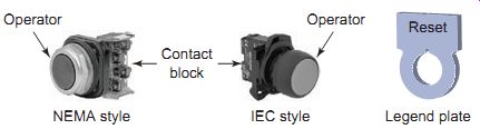
Ill. 6 Typical pushbutton assembly. Legend plate IEC style NEMA style;
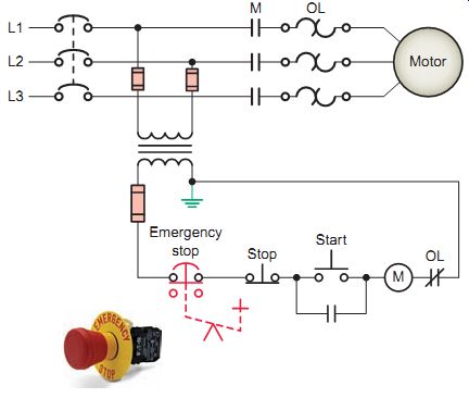
Ill. 7 Emergency stop pushbutton.
Legend plate--Legend plates are the labels that are installed around a push button and identify its purpose. They come in many sizes, colors, and languages.
Examples of label text include START, STOP, FWD, REV, JOG, UP, DOWN, ON, OFF, RESET, and RUN.
Contact block -The contact block is the part of the pushbutton assembly that's activated when the button is pressed. The contact block may house many sets of contacts that open and close when you operate the push button. The normal contact configuration allows for one normally open and one normally closed set of contacts within a contact block. A push button may contain stacked contacts that change state with a single push of a single button.
The contacts of the contact block itself are spring loaded and return to their normal on or off state when the operator is released. However, when contact blocks are attached to a pushbutton operator, their switching action is determined in part by that of the operator. Pushbutton operators are avail able for momentary or maintained operation. Momentary type pushbutton operators return to their normal on or off state as soon as the operator is released. Unlike momentary pushbutton operators, maintained types require you to press and release the operator to switch the contacts to their on state and to press and release the operator a second time to return the contacts to their off state.
Standard three-wire motor control circuits use a holding circuit in conjunction with momentary start/stop pushbutton operators for starting and stopping a motor. Emergency stop switches are devices that users manipulate to initiate the complete shutdown of a machine, system, or process. Emergency stop push buttons installed in motor control circuits are normally maintained-contact types with mushroom-type heads. Using maintained contacts in emergency stop push buttons prevents a motor control process from restarting until the maintained push button is physically reset. The Occupational Safety and Health Administration (OSHA) regulations require that once the emergency stop switch has activated, the control process cannot be started again until the actuating stop switch has been reset to the on position. Ill. 7 shows a typical motor control circuit that includes an emergency stop push button. The normally closed maintained contacts of the emergency stop push button will open when the push button is pressed and remain open until it’s manually reset. Since the emergency stop contacts are held open by the pushbutton operator mechanism, the motor won’t operate if the start button is pressed. In order to restart the motor after the emergency stop push button has been activated you must first reset the emergency stop push button and then press the start button.
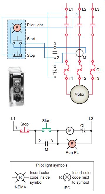
Ill. 8 Remote start/stop station with run pilot light.
Ill. 9 Transformer pilot light.
Ill. 10 Push-to-test pilot light.
Ill. 11 Three-position selector switch.
Ill. 12 Drum switch used for reversing the direction of rotation of
a three-phase motor.
Pilot Lights
Pilot lights provide visual indication of the status for many motor-controlled processes permitting personnel at remote locations to observe the current state of the operation. They are commonly used to indicate whether or not a motor is operating. Ill. 8 shows the circuit for a start/stop push button station with a pilot light connected to indicate when the starter is energized. For this application the red pilot light is energized to show when the motor is operating, as the motor and drive are located at some remote location not within view of the pushbutton station.
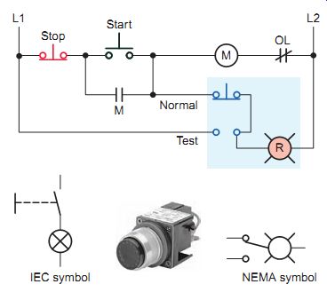
Pilot lights are available in both full-voltage and low voltage types. A transformer pilot light, such as shown in Ill. 9, uses a step-down transformer to reduce the operating voltage supplied to the lamp. The primary voltage of the transformer is matched to the input voltage of L1 and L2, while the secondary voltage is matched to that of the lamp. The lower lamp voltage can provide a margin of safety if the lamp requires replacement while the control circuit's energized. Also available are illuminated units utilizing integrated LEDs, which operate at 6 to 24 V, AC or DC.
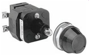
Dual input "push-to-test" pilot lights are designed to reduce the time required to troubleshoot a suspected faulty lamp. Push-to-test pilot lights can be energized from two separate input signals of the same voltage. This is done by wiring the "test" terminal to the second input signal as illustrated in the push-to-test circuits of Ill. 10.
Pressing the push-to-test pilot light opens the normal signal input to the light while at the same time completing a path directly to L1 and illuminating the lamp if the unit's not at fault.
Selector Switch
The difference between a push button and selector switch is the operator mechanism. A selector switch operator is rotated (instead of pushed) to open and close contacts of the attached contact block. Switch positions are established by turning the operator knob right or left. These switches may have two or more selector positions, with either maintained contact position or spring return to give momentary contact operation.
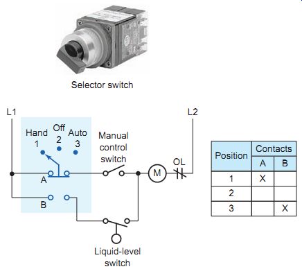
The circuit of Ill. 11 is an example of a three-position selector switch used to select three different operating modes for control of a pump motor. The operation of the circuit can be summarized as follows:
• In the HAND position, the pump can be started by closing the manual control switch. It can be stopped by opening the manual control switch or selecting the OFF position of the selector switch. The liquid level switch has no effect in either the HAND or OFF position.
• When AUTO is selected, the liquid-level switch controls the pump. At a predetermined level the liquid level switch will close, starting the pump. At another predetermined level, the liquid level switch will open, stopping the pump.
• The selector switch contact position and resultant state are identified by means of the table shown.
Contacts are marked as A and B, while positions are marked as 1, 2, and 3. An X in the table indicates the contact is closed at that particular position.
Drum Switch
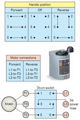
A drum switch consists of a set of moving contacts and a set of stationary contacts that open and close as the shaft is rotated. Reversing drum switches are designed to start and reverse motors by connecting them directly across the line. The drum switch may be used with squirrel-cage motors; single-phase motors designed for reversing service; and series, shunt, and compound DC motors. Ill. 12 shows how a drum switch is wired to reverse the direction of rotation of a three-phase motor.
Reversal of the direction of rotation is accomplished by interchanging two of the three main power lines to the motor. The internal switching arrangements and resulting motor connections, for forward and reverse, are shown in the tables. Note that the drum switch is used only as a means for controlling the direction of rotation of the motor and does not provide overcurrent or over load protection. A good rule for most motors is that they should be allowed to come to a complete stop before you reverse their direction.
Ill. 11 Three-position selector switch.
Ill. 12 Drum switch used for reversing the direction of rotation of
a three-phase motor.
QUIZ:
1. List three examples of primary motor control devices.
2. List three examples of pilot motor control devices.
3. What do the terms normally open and normally closed refer to when used in defining the switching action of a pushbutton switch?
4. The types of enclosures used to house motor control devices have been standardized by NEMA. What criteria are used to classify NEMA enclosure types?
5. Name the three basic parts of a standard pushbutton assembly.
6. Compare the operation of momentary and maintained pushbutton operators.
7. What is the OSHA requirement for resetting emergency stop switches?
8. A pilot light is to be connected to indicate when a magnetic starter is energized. Across what component of the circuit should the pilot light be connected?
9. Explain how a push-to-test pilot light operates.
10. Compare the way in which pushbutton and selector switch operators actuate contacts.
11. When a drum switch is used for starting and reversing a three-phase squirrel-cage motor, how is the reversing action accomplished?
Mechanically Operated Switches
Limit Switches
A mechanically operated switch is one that's controlled automatically by factors such as pressure, position, and temperature. The limit switch, illustrated in Ill. 13, is a very common type of mechanically operated motor control device. Limit switches are designed to operate only when a predetermined limit's reached, and they are usually actuated by contact with an object such as a cam.
These devices take the place of human operators. They are often used in the control circuits of machine processes to govern the starting, stopping, or reversal of motors.
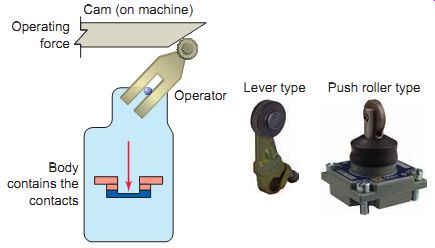
Ill. 13 Limit switch. Body contains the contacts; Operator; Lever type;
Push roller type; Cam (on machine); Operating force
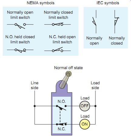
Ill. 14 Limit switch symbols and configuration. NEMA symbols IEC symbols;
Normally open limit switch; Normally closed limit switch;
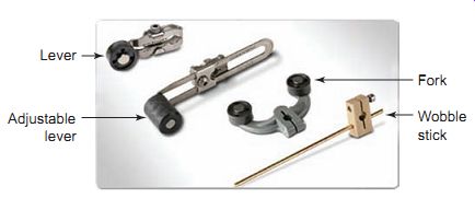
Ill. 15 Limit switch operators. Adjustable lever; Wobble stick
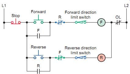
Ill. 16 Limit switches providing overtravel protection. Reverse direction
limit switch; Forward direction limit switch
Ill. 17 Snap-action micro limit switch.
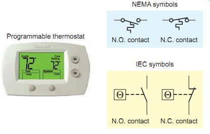
Ill. 19 Temperature switch symbols. Programmable thermostat; NEMA symbols;
IEC symbols N.O. contact N.C. contact N.O. contact N.C. contact
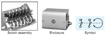
Ill. 18 Rotating cam limit switch. Symbol Enclosure Switch assembly
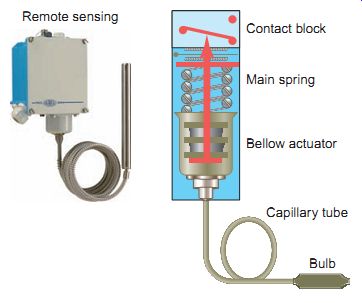
Ill. 20 Capillary tube temperature switch. Remote sensing; Capillary
tube, Bulb, Contact block, Main spring, Bellow actuator.
Limit switches are constructed of two main parts: the body and the operator head (also called the actuator). The body houses the contacts that are opened or closed in response to the movement of the actuator. Contacts may consist of the normally open, normally closed, momentary (spring-returned), or maintained-contact types. The terms normally open and normally closed refer to the state of the contacts when the switch is in its normally deactivated state. Ill. 14 shows the standard symbols used to represent limit switch contacts as follows:
• The N.O. held closed symbol indicates that the contact is wired as an N.O. contact, but when the circuit's in its normal off state, some part of the machine holds the contact closed.
• The N.C. held open symbol indicates that the con tact is wired as an N.C. contact, and some part of the machine in its normal off state holds the contact open.
• A contact block with one N.O. and one N.C. set of contacts is the most common configuration. When you have two or more sets of contacts in a limit switch that are electrically isolated, one must wire the loads that these contacts are controlling on the same side of the line.
Limit switches come with a wide variety of operators designed for a broad range of applications.
These include:
• Lever type, which consists of a single arm with a roller attached at the end to help prevent wear. The length of the lever may be fixed or adjustable. Adjustable types are used in applications that require adjustment of the actuator length or travel.
• Fork lever, which is designed for applications where the actuating object travels in two directions. A typical application is a machine bed that automatically alternates back and forth.
• Wobble stick, which is used in applications that require detection of a moving object from any direction rather in one or two directions along a single plane. They may be constructed of steel, plastic, Teflon, or nylon and are connected to the limit switch by a flexible spring attachment.
• Push roller type, which operates by a direct forward movement into the limit switch. This type has the least amount of travel compared to other types and is commonly used to prevent overtravel of a machine part or object. The limit switch contacts are connected so as to stop the forward movement of the object when it makes contact with it.
A common application for limit switches is to limit the travel of electrically operated doors, conveyors, hoists, machine tool worktables, and similar devices. Ill. 16 shows the control circuit for starting and stopping a motor in the forward and reverse directions with two limit switches providing overtravel protection. The operation of the circuit can be summarized as follows:
- • Pressing the momentary forward push button completes the circuit for the F coil, closing the normally open maintaining contact and sealing in the circuit for the forward starter coil.
- • At the same instant, the normally closed interlock contact F opens to prevent the reverse direction of the motor.
- • To reverse the motor direction the operator must first press the stop button to deenergize the F coil and then press the reverse push button.
- • If overtravel position should be reached in either the forward or reverse direction, the respective N.C. limit switch will open to prevent any further travel in that direction.
- • The forward direction is also interlocked with a normally closed R contact.
The micro limit switch, shown in Ill. 17, is a snap action switch housed in a small enclosure. Snap action switches are mechanical switches that produce a very rapid transfer of contacts from one position to another.
They are useful in situations that require a fast opening or closing of a circuit. In a snap-action switch, the actual switching of the circuit takes place at a fixed speed no matter how quickly or slowly the activating mechanism moves.
One difference between traditional limit switches and micro limit switches is the electrical configuration of the switch contacts. Micro switches use a single-pole, double-throw, contact arrangement that has one terminal connected as a common between the normally open and normally closed contacts instead of two electrically isolated contacts. The micro switch body is normally constructed of molded plastic, which offers a limited amount of electrical isolation and physical protection for contacts. Because of this, these switches are normally mounted within enclosures where there is a lower risk of physical damage. When used in conjunction with equipment doors, micro limit switches function as safety devices that are interlocked with control circuitry to prevent the process from operating if the door isn't in place.
The rotating cam limit switch, shown in Ill. 18, is a control device that senses angular shaft rotation within 360 degrees and then activates contacts. They are typically used with machinery having a repetitive cycle of operation, where motion is correlated to shaft rotation.
The switch assembly consists of one or more snap-action switches that are operated by cams assembled on a shaft.
Cams are independently adjustable for operating at different locations within a complete 360 degree rotation.
Temperature Control Devices
Temperature control devices (also called thermostats, depending on the application) monitor the temperature or changes in temperature for a particular process. Although there are many types available, they are all actuated by some specific environmental temperature change. Temperature switches open or close when a designated temperature is reached. Temperature control devices are used in heating or cooling applications where temperature must be maintained within preset limits. Symbols used to represent temperature switches are shown in Ill. 19.
Temperature switches are designed to work with a number of different operating principles. These devices typically comprise sensing elements and switching contacts housed in a single mechanical assembly. Switches may open or close on temperature rise, depending on their internal construction. The capillary tube temperature switch, illustrated in Ill. 20, operates on the principle that a temperature-sensitive liquid will expand and contract with a change in temperature. Pressure in the system changes in proportion to temperature and is transmitted to the bellows through a bulb and capillary tube. As the temperature rises, the pressure in the tube increases. Similarly, as the temperature decreases, the pressure in the tube deceases.
Bellows motion, in turn, is transmitted through a mechanical linkage to actuate a precision switch at a predetermined setting. Capillary tube-type temperature switches can be connected to a remote fluid-containing bulb, allowing the switch element to be remote from the sensing bulb and environment or process under control.
Ill. 21 shows the wiring diagram for the automatic control of a 230-V fractional-horsepower fan motor that utilizes a temperature switch. Temperature switches rated to carry motor current may be used with fractional-horsepower manual starters. Note that a double-pole manual starter is used. This type of starter is required when both line leads to the motor must be switched, such as for a 230-V, single-phase source. When the three-position selector switch is in the Auto position, the temperature switch reacts to a preset rising temperature to automatically switch the motor on. When the temperature drops below the preset value, the contacts open to turn the motor off.
Pressure Switches
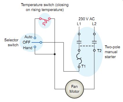
Ill. 21 Temperature switch utilized as part of a motor control circuit.
Selector switch Auto OFF Hand Temperature switch (closing on rising temperature);
Two-pole manual starter; Fan Motor

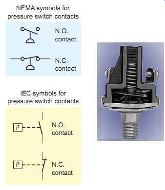
Ill. 22 Pressure switch symbols. Made by Honeywell, www.honeywell.com.
NEMA symbols for pressure switch contacts; IEC symbols for pressure switch
contacts
Ill. 23 Pressure switch used as part of an air compressor control system.
System on/off switch; Compressor motor starter coil; Pressure switch;
Compressor
Pressure switches are used to monitor and control the pressure of liquids and gases. They are commonly used to monitor a system and , in the event that pressure reaches a dangerous level, open relief valves or shut the system down.
The three categories of pressure switches used to activate electrical contacts are positive pressure, vacuum (negative pressure), and differential pressure. Symbols used to represent pressure switches are shown in Ill. 22.
Pressure switches are used in many different types of industries and applications. They can be used to control pneumatic systems, maintaining preset pressures between two values. The compressor circuit shown in Ill. 23 consists of a compressor drive motor, a compressor unit, and tank. The operation of the circuit can be summarized as follows:
- • The pressure switch is used to stop the motor when tank pressure reaches a preset limit.
- • When the preset system pressure is reached, the N.C. contacts of the pressure switch open to deenergize the motor starter coil and automatically switch the compressor motor off.
- • To prevent the motor from starting and stopping around the set point of the pressure switch, this type of switch has a built-in differential that allows it to close at one pressure and then open at a higher pressure. This is referred to as the pressure span.
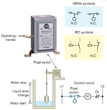
Ill. 24 Float switch symbols and circuit. Operating handle; N.O. N.C.
NEMA symbols IEC symbols; Motor stop Motor start Liquid level change;
Control circuit; Float switch
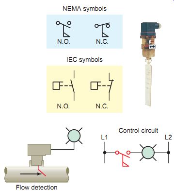
Ill. 25 Flow switch symbols and circuit. L1 L2 Control circuit; Flow
detection
Float and Flow Switches
A float switch is used to sense the height of a liquid. Float switches provide automatic control for motors that pump liquid from a sump or into a tank. The switch must be installed above the tank or sump, and the float must be in the liquid for the float switch to operate. For tank operation, a float operator assembly is attached to the float switch by a rod, chain or cable. The float switch is actuated according to the location of the float in the liquid.
There are several styles of float switches. One type uses a rod that has a float mounted on one end, as illustrated in Ill. 24. In this application a float switch is used to control the pump motor in an automatic tank-filling operation. The operation of the circuit can be summarized as follows:
• The float switch contacts are open when the float forces the operating lever to the up position.
• As the liquid level falls, the float and rod move downward.
• When the float reaches a preset low level, the float switch contacts close, activating the circuit and starting the pump motor to refill the tank.
• Adjustable stops on the rod determine the amount of movement that must take place before the switch contacts open or close.
A flow switch is used to detect the movement of air or liquid through a duct or pipe. In certain applications, it’s essential to be able to determine whether fluid is flowing in a pipeline, duct, or other conduit and to respond accordingly to such a determination. One of the simplest types of flow switch is the paddle type illustrated in Ill. 25. The paddle extends into the pipe and moves to close the electrical contacts of the flow switch when the fluid flow is sufficient to overcome the spring tension on the paddle. When the flow stops, the contacts open.
On most paddle-type flow switches the spring tension is adjustable, allowing for different flow rate adjustments.
QUIZ
- 1. Define the term mechanically operated switch.
- 2. In what way are limit switches normally actuated?
- 3. A control application calls for an N.C. held open limit switch. What type of connection does this imply?
- 4. List four common types of limit switch operator heads.
- 5. What is an important operating feature of a snap action micro limit switch?
- 6. In what way is the contact configuration of a traditional limit switch different from that of a micro limit switch?
- 7. For what types of machine control applications are rotating cam limit switches best suited?
- 8. How does a fluid capillary tube temperature switch actuate its electrical contact block?
- 9. In what types of applications are pressure switches used?
- 10. Compare the function of a float switch with that of a flow switch.
Cont. to part 2