AMAZON multi-meters discounts AMAZON oscilloscope discounts
Cont. from part 1
Transformer Voltage, Current, and Turns Ratio
The ratio of turns in a transformer's primary winding to those in its secondary winding is known as the turns ratio and is the same as the transformer's voltage ratio. E.g., if a transformer has a 10:1 turns ratio, then for every 10 turns on the primary winding there will be 1 turn on the secondary winding. Inputting 10 V to the primary winding steps down the voltage and will produce a 1-V output at the secondary winding. The exact opposite is true for a transformer with a 1:10 turns ratio. A transformer with a 1:10 turns ratio would have 1 turn on the primary winding for every 10 turns on the secondary winding. In this case, inputting 10 V to the primary winding steps up the voltage and will produce 100 volts at the secondary winding. The actual number of turns isn't important, just the turns ratio. A transformer turns ratio test set, such as that shown in Ill.19, can directly measure the turns ratio of single-phase transformers as well as three-phase transformers. Any deviations from rated values will indicate problems in transformer windings and in the magnetic core circuits.
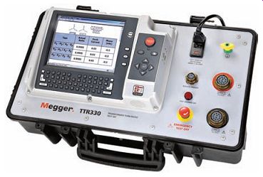
Ill.19 Transformer turns ratio test set. E.g., Megger, megger.com
The voltage ratio of an ideal transformer (one with no losses) is directly related to the turns ratio, while the cur rent ratio is inversely related to the turns ratio:
Turns primary/Turns secondary = Voltage primary/Voltage secondary = Current secondary/Current primary
The following table shows examples of some common single-phase transformer turns ratios based on primary and secondary voltage ratings.
Primary voltage | Secondary voltage | Turns ratio 480 V 240 V 2:1 480 V 120 V 4:1 480 V 24 V 20:1 600 V 120 V 5:1 600 V 208 V 2.88:1 208 V 120 V 1.73:1
Ill. 20 shows the schematic diagram of a step-up transformer wound with 900 turns on the primary winding and 1800 turns on the secondary winding. As a step-up unit, this transformer converts low-voltage, high-current power into high-voltage, low-current power. The transformer equations that apply to this circuit are as follows:
Turns ratio = Number of turns on the primary/Number of turns on the secondary
= 900 /1800 = 1 /2 = 1: 2 turns ratio
If the voltage of one winding and the turns ratio are known, the voltage of the other winding can be determined.
Primary voltage = Secondary voltage × Turns ratio Secondary voltage = Primary voltage/Turns ratio
If the current of one winding and the turns ratio are known, the current of the other winding can be determined.
Primary current = Secondary current/Turns ratio
Secondary current = Primary current × Turns ratio
Ill. 21 shows the schematic diagram of a step-down transformer wound with 1,000 turns on the primary winding and 50 turns on the secondary winding. As a step-down unit, this transformer converts high-voltage, low-current power into low-voltage, high-current power. A larger-diameter wire is used in the secondary winding to handle the increase in current. The primary winding, which doesn't have to conduct as much current, may be made of a smaller diameter wire. The transformer equations that apply to this circuit are the same as those for a step-up transformer:
Turns ratio = Number of turns on the primary / Number of turns on the secondary
If the voltage of one winding and the turns ratio are known, the voltage of the other winding can be determined.
Primary voltage = Secondary voltage × Turns ratio
Secondary voltage = Primary voltage/ Turns ratio
If the current of one winding and the turns ratio are known, the current of the other winding can be determined.
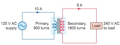
Ill.20 Step-up transformer.
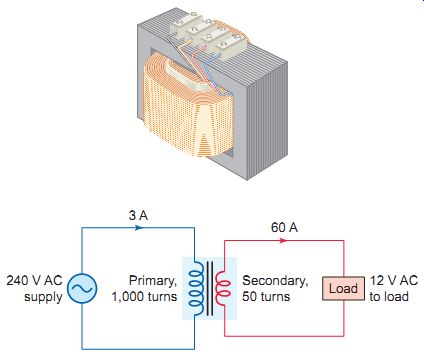
Ill.21 Step-down transformer.
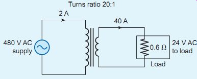
Ill.22 Step-down transformer connected to a resistive load.
Secondary current = Primary current × Turns ratio
A transformer automatically adjusts its input current to meet the requirements of its output or load current. If no load is connected to the secondary winding, only a small amount of current, known as the magnetizing current (also known as exciting current), flows through the primary winding. Typically, the transformer is designed in such a way that the power consumed by the magnetizing current is only enough to overcome the losses in the iron core and in the resistance of the wire with which the primary is wound.
If the secondary circuit of the transformer becomes over loaded or shorted, primary current increases dramatically also. It’s for this reason that a fuse is placed in series with the primary winding to protect both the primary and secondary circuits from excessive current. The most critical parameter of a transformer is its insulation qualities. Failure of a transformer, in most instances, can be traced to a breakdown of the insulation of one or more of the windings.
For a purely resistive load, according to Ohm's law, the amount of secondary winding current equals the secondary voltage divided by the value of the load resistance connected to the secondary circuit (a negligible coil winding resistance is assumed). Ill.22 shows the schematic diagram of a step-down transformer with a 20:1 turns ratio connected to a 0.6-ohm resistive load. The transformer equations that apply to this circuit are as follows:
Secondary winding current = Secondary voltage/Load resistance
Primary winding current = Secondary winding current/Turns ratio
Transformer Power Rating
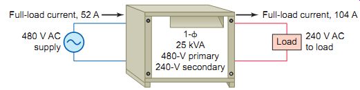
Ill.23 Single-phase 25-kVA transformer, rated 480/240 V full-load current.
Full-load current, 52 A
480 V AC supply; Full-load current, 104 A; 25 kVA 480-V primary 240-V secondary
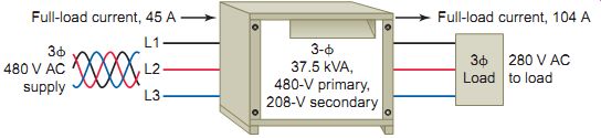
Ill.24 Three-phase 37.5-kVA transformer, rated 480/240 V full-load current.
Just as horsepower ratings designate the power capacity of an electric motor, a transformer's kVA rating indicate its maximum power output capacity. Transformers' kVA ratings are calculated as follows:
Single-phase loads: kVA = I × E /1000
Three-phase loads: kVA = I × E x sqr-rt(3)/1000
The maximum power rating of a transformer can be found on the transformer's nameplate. Transformers are rated in volt-amperes (VA) or kilovolt-amperes (kVA). One may recall that volt-amperes is the total power supplied to the circuit from the source, and includes real (watts) and reactive (VAR) power. The primary and secondary full-load cur rents usually are not given. If the volt-ampere rating is given along with the primary voltage, then the primary full-load current can be determined using the following equations:
Single-phase: Full-load current = VA/Voltage
Three-phase: Full-load current =
Ill.23 shows the diagram for a single-phase 25-kVA transformer, rated 480 V primary and 240 V secondary. The rated full-load primary and secondary cur rents are calculated as follows:
Primary full-load current =
Secondary full-load current = kVA × 1,000/Voltage
Ill.24 shows the diagram for a three-phase 37.5-kVA transformer, rated 480 volts primary and 208 V secondary. The rated full-load primary and secondary currents are calculated as follows:
PART 2 QUIZ
1. Define the terms primary and secondary as they apply to a transformer winding.
2. On what basis is a transformer classified as being a step-up or step-down type?
3. Explain how the transfer of energy takes place in a transformer.
4. In an ideal transformer, what is the relationship between:
a. The turns ratio and the voltage ratio?
b. The voltage ratio and current ratio?
c. The primary power and secondary power?
5. A step-down transformer with a turns ratio of 10:1 has 120 V AC applied to its primary coil winding. A 3-ohm load resistor is connected across the secondary coil. Assuming ideal transformer conditions, calculate the following:
a. Secondary coil winding voltage.
b. Secondary coil winding current.
c. Primary winding coil current.
6. A step-up transformer has a primary current of 32 A and an applied voltage of 240 V. The secondary coil has a current of 2 A. Assuming ideal transformer conditions, calculate the following:
a. Power input of the primary winding coil.
b. Power output of the secondary winding coil.
c. Secondary coil winding voltage.
d. Turns ratio
7. What is meant by the term transformer magnetizing, or exciting, current?
8. Why will a fuse placed in series with the primary coil winding protect both the primary and secondary coil winding circuits from excessive current?
9. Is transformer power rated in watts or volt-amperes? Why?
10. A transformer primary winding has 900 turns and the secondary winding has 90 turns. Which winding of the transformer has the larger-diameter conductor? Why?
11. The primary of a transformer is rated for 480 V and the secondary for 240 V. Which winding of the transformer has the larger-diameter conductor? Why?
12. A single-phase transformer is rated for 0.5 kVA, a primary voltage of 480 V, and a secondary voltage of 120 V. What is the maximum full load that can be supplied by the secondary?
PART 3: Transformer Connections and Systems
Transformer Polarity
Transformer polarity refers to the relative direction or polarity of the induced voltage between the high-voltage and low-voltage terminals of a transformer. An under standing of transformer polarity markings is essential in making three-phase and single-phase transformer connections. Knowledge of polarity is also required to connect potential and current transformers to power metering and protective relays.
On power transformers, the high-voltage winding leads are marked H1 and H2 and the low-voltage winding leads are marked X1 and X2 (Ill.25). By convention, H1 and X1 have the same polarity, which means that when H1 is instantaneously positive, X1 also is instantaneously positive. These markings are used in establishing the proper terminal connections when single-phase transformers are connected in parallel, series, and three-phase configurations.
In practice, the four terminals on a single-phase transformer are mounted in a standard way so the transformer has either additive or subtractive polarity. Whether the polarity is additive or subtractive depends on the location of the H and X terminals. A transformer is said to have additive polarity when terminal H1 is diagonally opposite terminal X1. Similarly, a transformer has sub tractive polarity when terminal H1 is adjacent to terminal X1. Ill.26 illustrates additive and subtractive transformer terminal markings along with a test circuit that can be used to verify markings. Also shown is a battery-operated transformer polarity checker that can perform the same test.
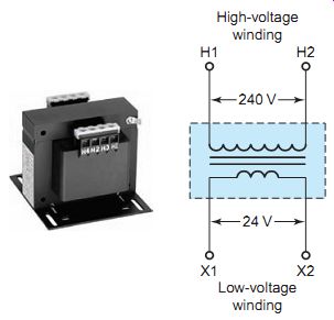
Ill.25 Transformer polarity markings. Rockwell Automation. High-voltage
winding; Low-voltage winding
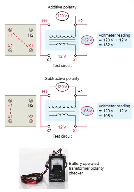
Ill.26 Additive and subtractive transformer terminal markings. Additive
polarity; Test circuit; Subtractive polarity; Voltmeter reading: _ 120
V _ 12 V _ 108 V; Battery operated transformer polarity checker
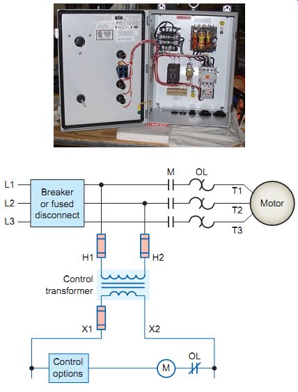
Ill.27 Motor control transformer wiring. Superior Panels, www.superiorpanels.com.
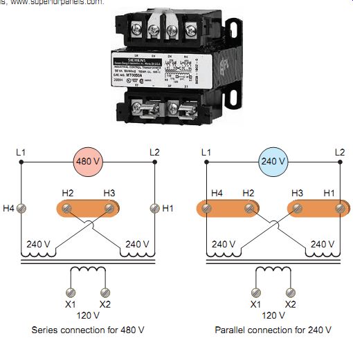
Ill.28 Typical dual-voltage 480-V and 240-V transformer connections. Siemens,
www.siemens.com. Parallel connection for 240 V Series connection for 480
V
Single-Phase Transformers
Motor control transformers are designed to reduce sup ply voltages to motor control circuits. Most AC commercial and industrial motors are operated from three-phase AC supply systems in the 208- to-600-V range. However, the control systems for these motors generally operate at 120 V. The major disadvantage to higher-voltage control schemes is that these higher voltages can be much more lethal than 120 V. Additionally, on a higher-voltage control system tied directly to the supply lines, when a short circuit occurs in the control circuit a line fuse will blow or a circuit breaker will trip, but may not do so right away.
In some cases light-duty contacts, such as those in stop buttons or relay contacts, can weld together before the protective device trips or blows.
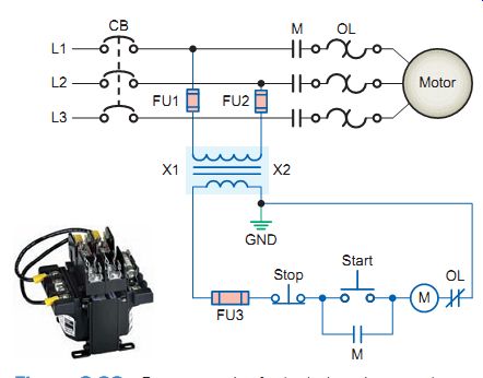
Ill.29 Fuse protection for both the primary and secondary of the transformer
and the correct ground connection for a grounded control system. solahd.com.
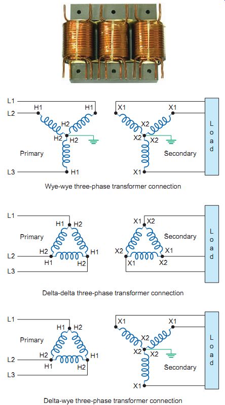
Ill.30 Common wye and delta transformer connections. Delta-wye three-phase
transformer connection
Ill.31 Three-phase, three-wire delta transformer connection supplying
power to a three-phase motor load. Wye-wye three-phase transformer connection;
Delta-delta three-phase transformer connection;
Step-down control transformers are installed when the control circuit components are not rated for the line voltage. Ill.27 shows the typical connection for a step-down motor control transformer. The primary side (H1 and H2) of the control transformer will be the line voltage, while the secondary voltage (X1 and X2) will be the voltage required for the control components.
Single-, dual-, and multi-tap primary control transformers are available. The versatile dual- and multitap primary transformers allow reduced control power from a variety of voltage sources to meet a wide array of applications.
Ill.28 shows the connections for a typical dual primary transformer used to step 240 or 480 V down to 120 V. The primary connections on the transformer are identified as H1, H2, H3, and H4. The transformer coil between H1 and H2 and the one between H3 and H4 are rated for 240 V each. The low-voltage secondary connections on the transformer, X1 and X2, can have 120 V from either a 480- or 240-V line. If the transformer is to be used to step 480 V down to 120 V, the primary windings are connected in series by a jumper wire or metal link. When the transformer is to be used to step 240 V down to 120 V, the two primary windings must be connected in parallel with each other.
The control transformer secondary can be grounded or ungrounded. Where grounding is provided, the X2 side of the circuit common to the coils must be grounded at the control transformer. This will ensure that an accidental ground in the control circuit won’t start the motor, or make the stop button or control inoperative. An additional requirement for all control transformers is that they be protected by fuses or circuit breakers. Depending on the installation, this protection can be placed on the primary, secondary, or both sides of the transformer. Ill.29 shows fuse protection for both the primary and secondary of the transformer and the correct ground connection for a grounded control system. The fuses must be properly sized for the control circuit. Section 430.72 of the Code lists requirements for the protection of transformers used in motor control circuits.
Ill.32 Wye-connected, three-phase, four-wire distribution system.
Three-Phase Transformers
Large amounts of power are generated and transmitted using high-voltage three-phase systems . Transmission voltages may be stepped down several times before they reach the motor load. This transformation is accomplished using three-phase wye - or delta -connected transformers or a combination of the two. Ill.30 illustrates some of the common three-phase wye and delta transformer connections. The connections are named after the way the windings are connected inside the transformer. Polarity markings are fixed on any transformer and the connections are made in accordance with them.
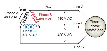
The transformers supplying motor loads can be connected on the load (secondary) side either in delta or in wye configuration. Two types of secondary distribution systems commonly used are the three-phase three-wire system and three-phase four-wire system. In both, the secondary voltages are the same for all three phases. The three-phase three-wire delta system is used for balanced loads and consists of three transformer windings connected end to end. Ill.31 shows a typical three-phase, three-wire delta transformer connection supplying power to a three-phase motor load. For a delta-connected transformer:
• The phase voltage (E phase) of the transformer secondary is always the same as the line voltage ( E line ) of the load.
• The line current ( I line ) of the load is equal to the phase current ( I phase ) of the transformer secondary multiplied by 1.73.
kVA (transformer) =
• The constant 1.73 is the square root of 3 and is used because the transformer phase windings are 120 electrical degrees apart.
The other commonly used three-phase distribution is the three-phase, four-wire system. Ill.32 shows a typical wye-connected three-phase, four-wire distribution system. The three phases connect at a common point, which is called the neutral. Because of this, none of the windings are affected by the other windings. Therefore, the wye three-phase, four-wire system is used for unbalanced loads. The phases are 120 electrical degrees apart; how ever, they have a common point. For a Wye transformer connected transformer:
• The phase-to-phase voltage is equal to the phase-to neutral voltage multiplied by 1.73.
• The line current is equal to the phase current.
kVA (transformer) =
• Common arrangements are 480Y/277 V and 208Y/120 V.
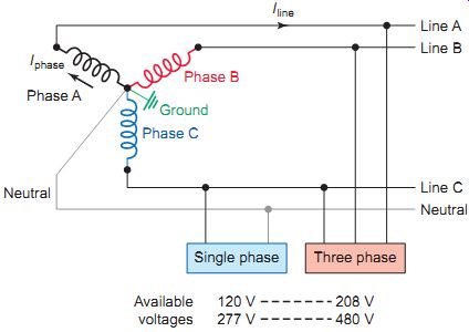
The delta-to-wye configuration is the most commonly used three-phase transformer connection. A typical delta to-wye voltage transformation is illustrated in Ill.33.
The secondary provides a neutral point for supplying line-to-neutral power to single-phase loads. The neutral point is also grounded for safety reasons. Three-phase loads are supplied at 208 V, while the voltage for single phase loads is 208 V or 120 V. When the transformer secondary supplies large amounts of unbalanced loads, the delta primary winding provides a better current balance for the primary source.
The autotransformer, shown in Ill.34, is a transformer consisting of a single winding with electrical connection points called taps. Each tap corresponds to a different voltage so that effectively a portion of the same inductor acts as part of both the primary and secondary winding. There is no electrical isolation between the input and output circuits, unlike the traditional two-winding transformer. The ratio of secondary to primary voltages is equal to the ratio of the number of turns of the tap they connect to. E.g., connecting at the 50% tap (middle) and bottom of the autotransformer output will halve the input voltage. Because it requires both fewer windings and a smaller core, an autotransformer for some power applications is typically lighter and less costly than a two-winding transformer. A variable autotransformer is one in which the output connection is made through a sliding brush. Variable autotransformers are widely used where adjustable AC voltages are required.
An autotransformer motor starter, such as shown in Ill.35, reduces inrush motor current by using a three-coil autotransformer in the line just ahead of the motor to step down the voltage applied to the motor terminals. By reducing the voltage, the current drawn from the line is reduced during start-up. During the starting period, the motor is connected to the reduced-voltage taps on the autotransformer. Once the motor has accelerated, it’s automatically connected to full-line voltage.
Instrument Transformers
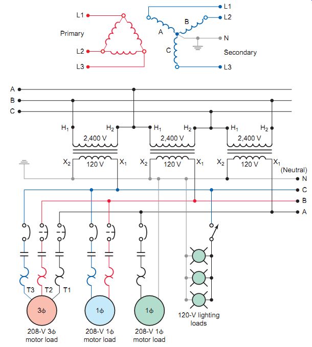
Ill.33 Typical delta-to-wye, three-phase, four-wire transformer configuration.
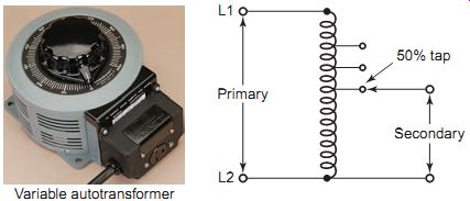
Ill.34 Autotransformer. Superior Electric, www.superiorelectric.com. Variable
autotransformer
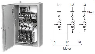
Ill.35 Autotransformer motor starter. Rockwell Automation.
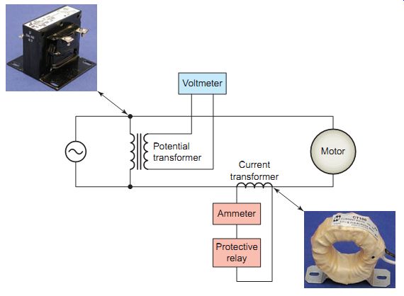
Ill.36 Instrument transformers. Hammond Manufacturing, hammondmfg.com.
Potential transformer; Current transformer; Ammeter; Protective relay;
Voltmeter; Motor
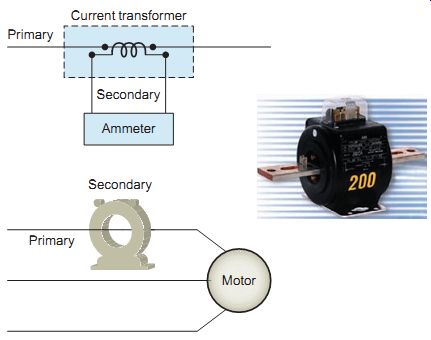
Ill.37 Current transformer. ABB, abb.com. Secondary; Primary; Current
transformer; Ammeter; Secondary; Primary; Motor
Instrument transformers are small transformers used in conjunction with instruments such as ammeters, voltmeters, power meters, and relays used for protective purposes (Ill.36). These transformers step down the voltage or current of a circuit to a low value that can be effectively and safely used for the operation of instruments. Instrument transformers also provide insulation between the instrument and the high voltage of the power circuit.
A potential (voltage) transformer operates on the same principle as a standard power transformer. The main difference is that the capacity of a potential transformer is relatively small compared to power transformers. Potential transformers have typical power ratings of from 100 VA to 500 VA. The secondary low-voltage side is usually wound for 120 V, which makes it possible to use standard instruments with potential coil ratings of 120 V. The primary side is designed to be connected in parallel with the circuit to be monitored.
A current transformer is a transformer that has its primary connected in series with the line conductor.
The conductor passes through the center of the transformer, as illustrated in Ill.37, and constitutes one primary turn. A current transformer supplies the instrument and /or protective device with a small cur rent that's proportional to the main current. The secondary winding consisting of many turns is designed to produce a standard 5A when its rated current is flowing in the primary. The secondary circuit of a cur rent transformer should never be opened when there is current in the primary winding. If the secondary isn't loaded, this transformer acts to step up the voltage to a dangerous level, because of the high turns ratio.
Therefore, a current transformer should always have its secondary shorted when not connected to an external load.
PART 3 QUIZ
1. Explain the way in which the high-voltage and lo voltage leads of a single-phase power transform are identified.
2. A polarity test is being made on the transformer shown in Ill.38.
a. What type of polarity is indicated?
b. What is the value of the voltage across the secondary winding?
c. Redraw the diagram with the unmarked leads of the transformer correctly labeled.
3. The control circuit for a three-phase 480-V motor is normally operated at what voltage? Why?
4. A 240/480-V dual-primary control transformer is to be operated from a 480-V three-phase system. How would the two primary windings be connected relative to each other? Why?
5. For the motor control circuit of Ill.39, assume the circuit's incorrectly grounded at X1 instead of correctly as shown at X2. With this incorrect connection, explain how the control circuit would operate if point 2 of the stop or start push button were to become accidentally grounded.
6. What are the two basic types of three-phase transformer configurations?
7. The phase-to-neutral voltage of a wye-connected, three-phase, four-wire distribution system is rated for 277 V. What would its phase-to-phase rating be?
8. Why is it necessary to apply the constant 1.73 (v 3) in three-phase circuit calculations?
9. Explain the basic difference between the primary and secondary circuits of a standard voltage transformer and an autotransformer.
10. How are autotransformers used to reduce the starting current for large three-phase motors?
11. Give two examples of the way in which instrument transformers are used.
12. Compare the primary connection of a potential transformer with that of a current transformer.
13. What important safety precaution should be followed when operating current transformers in live circuits?
14. The current rating of the primary winding of a current transformer is 100 A and its secondary rating is 5 A. An ammeter connected across the secondary indicates 4 A. What is the value of the current flow in the primary?
TROUBLESHOOTING EXAMPLES:
1. The control transformer for an across-the-line three-phase motor starter is tested and found to have an open in the secondary winding. Discuss what would occur if an attempt where made to temporarily operate the control system directly from two of the three-phase supply lines.
2. The two primary windings of a dual-primary control transformer (240 V or 480 V) are to be connected in parallel to step the line voltage of 240 V down to a control voltage of 120 V. Assuming the two primary windings are incorrectly connected in series instead of parallel what effect would this have on the control circuit?
DISCUSSION TOPICS and CRITICAL THINKING:
1. Discuss how electric power might be distributed within a small commercial or industrial site.
2. Research the specifications for a typical four-wire electrical power panelboard capable of feeding single-phase and three-phase loads. Include in your findings:
• All electrical specifications
• Internal bus layout
• Connections for single-phase and three-phase loads