AMAZON multi-meters discounts AMAZON oscilloscope discounts
Goals:
1. Understand the principles that are used to efficiently transmit power from the power generating plant to the customer.
2. Recognize the different sections and functions of a unit substation.
3. Differentiate between the service entrance, feeders, and branch circuits of the electrical distribution system within a building.
4. Be familiar with the function and types of race ways used in electrical distribution systems.
5. Explain the function of switchboards, panel boards, and motor control centers.
6. Understand the theory of operation of a transformer.
7. Properly connect single-phase and three-phase transformers as part of a motor power and control circuit.
Transformers transfer electric energy from one electric circuit to another by means of electromagnetic mutual induction. In its broadest sense, a distribution system refers to the manner in which electrical energy is transmitted from the generators to its many points of use.
In this section we will study the role that transformers play in motor power distribution and control systems.
PART 1: Power Distribution Systems
Transmission Systems
The central-station system of power generation and distribution enables power to be produced at one location for immediate use at another location many miles away. Transmitting large amounts of electric energy over fairly long distances is accomplished most efficiently by using high voltages. Ill.1 illustrates the typical transformation stages through which the distribution system must go in delivering power to a commercial or industrial user.
Without transformers the widespread distribution of electric power would be impractical. Transformers are electrical devices that transfer energy from one electrical circuit to another by magnetic coupling. Their purpose in a power distribution system is to convert AC power at one voltage level to AC power of the same frequency at another voltage level. High voltages are used in transmission lines to reduce the amount of current flow. The power transmit ted in a system is proportional to the voltage multiplied by the current. If the voltage is raised, the current can be reduced to a smaller value, while still transmitting the same amount of power. Because of the reduction of current flow at high voltage, the size and cost of wiring are greatly reduced. Reducing the current also minimizes voltage drop ( IR) and amount of power lost ( I^2 R ) in the lines.
The circuits of Ill.2 illustrate how the use of high voltage reduces the required amount of transmission current required for a given load. Their operation is summarized as follows:
• 10,000 W of power is to be transmitted.
• When transmitted at the 100-V level, the required transmission current would be 100 A:
P = V × I = 100 V × 100 A = 10,000 W
• When the transmission voltage is stepped up to 10,000 V, a current flow of only 1 A is needed to transmit the same 10,000 W of power:
P = V × I = 10,000 V × 1 A = 10,000 W
There are certain limitations to the use of high volt age in power transmission and distribution systems. The higher the voltage, the more difficult and expensive it becomes to safely insulate between line wires, as well as from line wires to ground. The use of transformers in power systems allows generation of electricity at the most suitable voltage level for generation and at the same time allows this voltage to be changed to a higher and more economical voltage for transmission. At the load centers transformers allow the voltage to be lowered to a safer voltage and more suitable voltage for a particular load.
Power grid transformers, used to step up or step down voltage, make possible the conversion between high and low voltages and accordingly between low and high cur rents (Ill.3). By use of transformers, each stage of the system can be operated at an appropriate voltage level. Single-phase three-wire power is normally supplied to residential customers, while three-phase power is sup plied to commercial and industrial customers.
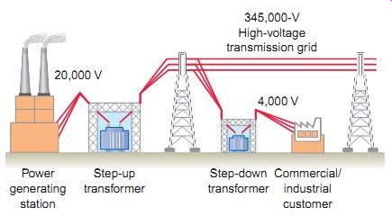
Ill.1 Transformation stages of a power distribution system.
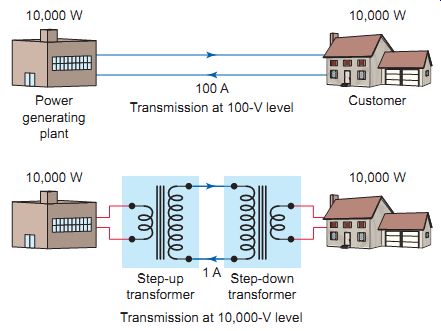
Ill.2 High voltage reduces the required amount of transmission current
required. Power generating plant (10,000 W) Transmission at 100-V level;
Customer (10,000 W); Transmission at 10,000-V level
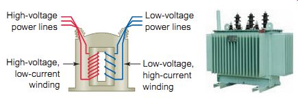
Ill.3 Power grid transformer. ABB, www.abb.com. High-voltage power lines;
high-voltage, low-current winding; Low-voltage power lines Low-voltage,
high-current winding
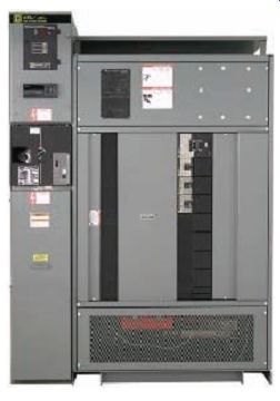
Ill.4 Factory assembled unit substation. By Schneider Electric.
Ill.5 Single-line diagram for a typical unit substation. Primary service
feeder; Low-voltage main bus; Main secondary breaker; Branch feeders
Unit Substations
Electric power comes off the transmission lines and is stepped down to the distribution lines. This may happen in several phases. The place where the conversion from transmission to distribution occurs is in a power substation. It has transformers that step transmission voltage levels down to distribution voltage levels. Basically a power substation consists of equipment installed for switching, changing, or regulating line voltages. Substations provide a safe point in the electricity grid system for disconnecting the power in the event of trouble, as well as a convenient place to take measurements and check the operation of the system.
The power needs of some users are so great that they are fed through individual substations dedicated to them. These secondary unit substations form the heart of an industrial plant's or commercial building's electrical distribution.
They receive the electric power from the electric utility and step it down to the utilization voltage level of 600 V nominal or less for distribution throughout the building. Unit substations offer an integrated switchgear and transformer package. A typical unit substation is shown in Ill.4.
Substations are factory assembled and tested and therefore require a minimum amount of labor for installation at the site. The unit substation is completely enclosed on all sides with sheet metal (except for the required ventilating openings and viewing windows) so that no live parts are exposed.
Access within the enclosure is provided only through inter locked doors or bolted-on removable panels.
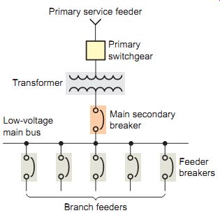
The single-line diagram for a typical unit substation is illustrated in Ill.5. It consists of the following sections:
High-voltage primary switchgear -This section incorporates the terminations for the primary feeder cables and primary switchgear, all housed in one metal-clad enclosure.
Transformer section--This section houses the transformer for stepping down the primary voltage to the low-voltage utilization level. Dry-type, air-cooled transformers are universally used because they don’t require any special fireproof vault construction.
Low-voltage distribution section--This switchboard section provides the protection and control for the low-voltage feeder circuits. It may contain fusible switches or molded-case circuit breakers in addition to metering for the measurement of voltage, cur rent, power, power factor, and energy. The secondary switchgear is intended to be tripped out in the event of overload or faults in the secondary circuit fed from the transformer; the primary gear should trip if a short circuit or ground fault occurs in the transformer itself.
Before attempting to do any work on a unit substation, first the loads should be disconnected from the transformer and locked open. Then the transformer primary should be disconnected, locked out, and grounded temporarily if over 600 V.
Ill.6 Typical commercial/industrial distribution system.
Ill.7 Single-line diagram for a typical electrical distribution system.
Electricity supply system; Branch circuits Service entrance Feeders; Lighting
panelboard; Lighting and receptacles; Specific purpose equipment; Motor
control center
Distribution Systems
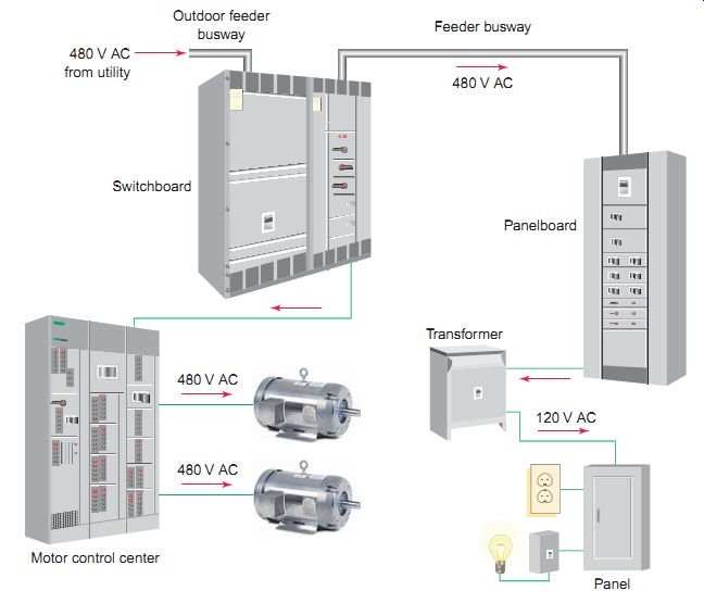
Distribution systems used to distribute power throughout large commercial and industrial facilities can be complex.
Power must be distributed through various switchboards, transformers, and panelboards (Ill.6) without any component overheating or unacceptable voltage drops.
This power is used for such applications as lighting, heating, cooling, and motor-driven machinery.
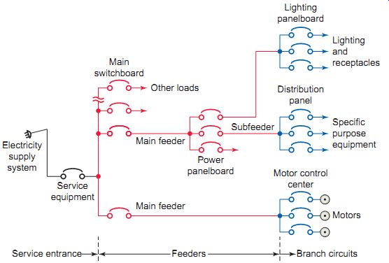
The single-line diagram for a typical electrical distribution system within a large premise is shown in Ill.7.
Typically the distribution system is divided into the following sections:
Service entrance--This section includes conductors for delivering energy from the electricity supply sys tem to the premises being served.
Feeders -A feeder is a set of conductors that originates at a main distribution center and supplies one or more secondary or branch circuit distribution centers.
This section includes conductors for delivering the energy from the service equipment location to the final branch circuit overcurrent device; this protects each piece of utilization equipment. Main feeders originate at the service equipment location, and subfeeders originate at panelboards or distribution centers at locations other than the service equipment location.
Branch circuits -This section includes conductors for delivering the energy from the point of the final overcurrent device to the utilization equipment. Each feeder, subfeeder, and branch circuit conductor in turn needs its own properly coordinated overcurrent protection in the form of a circuit breaker or fused switch.
Correct selection of conductors for feeders and branch circuits must take into account ampacity, short-circuit, and voltage-drop requirements. Conductor ampacity refers to the maximum amount of current the conductor can safely carry without becoming overheated. The ampacity rating of conductors in a raceway depends on the conductor material, gauge size, and temperature rating; the number of current-carrying conductors in the raceway; and the ambient temperature.
The National Electrical Code (NEC) contains tables that list the ampacity for approved types of conductor size, insulation, and operating conditions. NEC rules regarding specific motor installations will be covered throughout the text. Installers should always follow the NEC, valid state and local codes, manufacturers' instructions, and project specifications when installing motors and motor controllers.
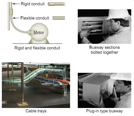
All conductors installed in a building must be properly protected, usually by installing them in raceways. Race ways provide space, support, and mechanical protection for conductors, and they minimize the hazards from electric shocks and electric fires. Commonly used types of raceways found in motor installations are illustrated in Ill.8 and include:
Conduits--Conduits are available in rigid and flexible, metallic and nonmetallic types. They must be properly supported and have sufficient access points to facilitate the installation of the conductors. Conduits must be large enough to accommodate the number of conductors, based generally, on a 40 percent fill ratio.
Cable trays--Cable trays are used to support feeder cables where a number of them are to be run from the same location. They consist of heavy feeder conductors run in troughs or trays.
Low-impedance busways (bus duct)--The busways are used in buildings for high-current feeders. They consist of heavy bus bars enclosed in ventilated ducts.
Plug-in busways -These busways are used for over head distribution systems. They provide convenient power tap-offs to the utilization equipment.
Ill.8 Common types of raceways.
Busway: Siemens.com. Cable tray Hyperline Systems (www.hyperline.com). Rigid and f lexible conduit; Rigid conduit; Flexible conduit; Motor; Busway sections bolted together
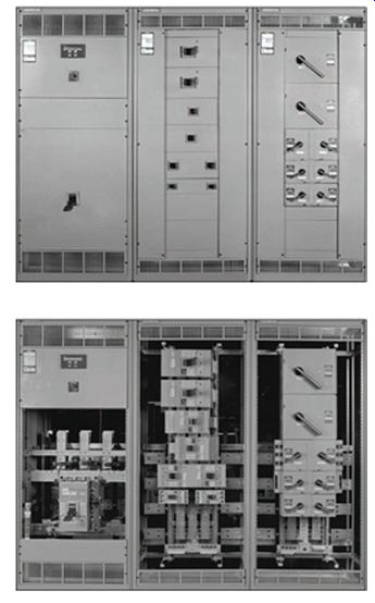
Ill.9 Combination service entrance switchboard. Branch circuit feeders;
Main feeder from switchboard; Panelboard; Manuf: Siemens
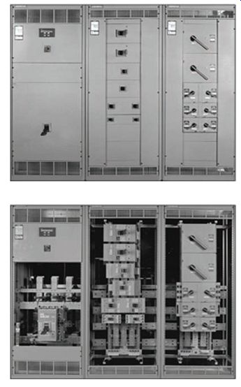
Ill.10 Typical panelboard installations. Manuf. Schneider Electric.
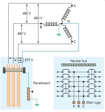
Ill.11 Wiring for a 277/480-V, three-phase, four-wire panelboard.
Switchboards and Panelboards
The Code defines a switchboard as a single panel or group of assembled panels with buses, overcurrent devices, and instruments. Ill.9 shows a typical combination service entrance and switchboard installed in a commercial building. The service entrance is the point where electricity enters the building. The switchboard has the space and mounting provisions required by the local utility for metering its equipment and incoming power. The switchboard also controls the power and protects the distribution system through the use of switches, fuses, circuit breakers, and protective relays. Switchboards that have more than six switches or circuit breakers must include a main switch to protect or disconnect all circuits.
A panelboard contains a group of circuit breaker or fuse protective devices for lighting, convenience receptacles, and power distribution branch circuits. Panelboards (sometimes referred to as load centers) are placed in a cabinet or cutout box, which is accessible only from the front, and have dead fronts. A dead front is defined in the Code as having no exposed live parts on the operating side of the equipment. The panelboard is usually supplied from the switchboard and further divides the power distribution system into smaller parts. Panelboards make up the part of the distribution system that provides the last centrally located protection for the final power run to the load and its control circuitry. Panelboards suitable as service equipment are so marked by the manufacturer.
Ill.11 shows the typical internal wiring for a 277/480-V, three-phase, four-wire panelboard equipped with circuit breakers. This popular system used in industrial and commercial installations is capable of supplying both three-phase and single-phase loads. From neutral (N) to any hot line, 277 V single-phase for fluorescent lighting can be obtained. Across the three hot lines (A-B-C) 480 V three-phase is present for supplying motors.
The proper grounding and bonding of electrical distribution systems in general and panelboards in particular are very important. Grounding is the connection to earth, while bonding is the connection of metal parts to provide a low impedance path for fault current to aid in clearing the overcurrent protection device and to remove dangerous current from metal that's likely to become energized.
The main bonding jumper gives you system grounding. If a transformer is immediately upstream of the panelboard, you must bond the neutral bus or neutral conductor to the panel enclosure and to a (bare) grounding-electrode conductor as illustrated in Ill.12.
The Code requires the panelboard cabinets, frames, and the like to be connected to an equipment grounding conductor, not merely grounded. A separate equipment grounding terminal bar must be installed and bonded to the panelboard for the termination of feeder and branch circuit equipment grounding conductors (Ill.13). The equipment grounding bus is non-insulated and is mounted inside the panelboard and connects directly to the metal enclosure.
A busbar can be defined as a common connection for two or more circuits. The Code requires that busbars be located so as to be protected from physical damage and held firmly in place. Three-phase busbars are required to have phases in sequence so that an installer can have the same fixed phase arrangement in each termination point in any panel or switchboard. As established by NEMA, the phase arrangement on three-phase buses shall be A, B, C front to back, top to bottom, or left to right as viewed from the front of the switchboard or panelboard (Ill.14).
Panelboards are classified as main breaker or main lug types. Main breaker-type panelboards have the incoming supply cables connected to the line side of a circuit breaker, which in turn feeds power to the panelboard. The main breaker disconnects power from the panelboard and protects the system from short circuits and overloads. A main lug panelboard does not have a main circuit breaker. The incoming supply cables are connected directly to the busbars.
Primary overload protection isn't provided as an integral part of the panelboard. It must be externally provided. Normally panelboard circuit terminals are required to be labeled or to have a wiring diagram. One scheme (sometimes called NEMA numbering) uses odd numbers on one side and even on the other, as illustrated in Ill.15.
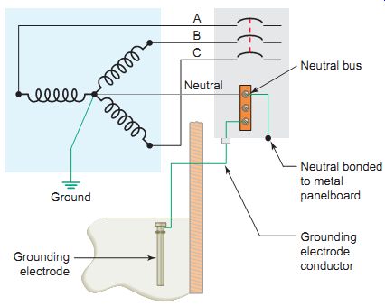
Ill.12 Panelboard grounding and bonding. Grounding electrode; Neutral
bus; Neutral bonded to metal panelboard; Grounding electrode conductor
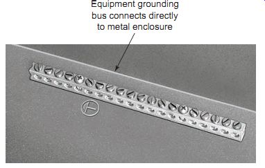
Ill.13 Equipment grounding bus. Equipment grounding bus connects directly
to metal enclosure. By Schneider Electric.
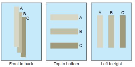
Ill.14 Phase arrangement on 3-phase buses. Front to back Top to bottom
Left to right
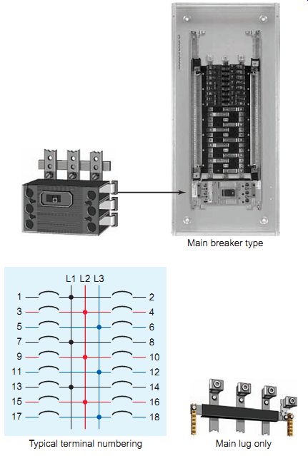
Ill.15 Panelboard configurations. siemens.com. Main breaker type; Main
lug only.
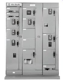
Ill.16 Typical motor control center. Rockwell Automation.
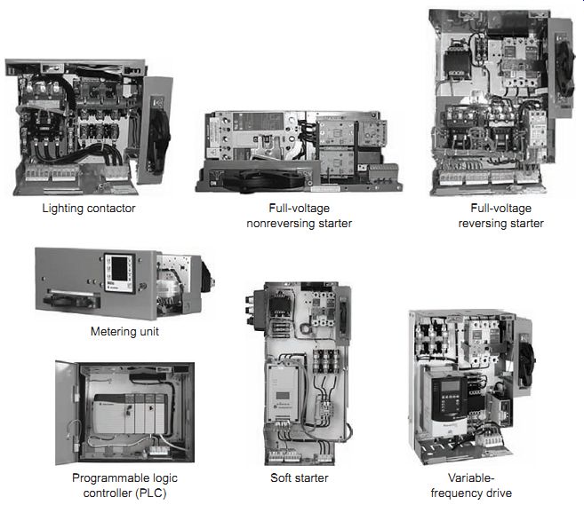
Ill.17 Typical motor control center unit types. Lighting contactor; Programmable
logic controller (PLC); Metering unit; Full-voltage nonreversing starter;
Soft starter; Full-voltage reversing starter; Variable-frequency drive
Motor Control Centers (MCCs)
At times a commercial or industrial installation will require that many motors be controlled from a central location.
When this is the case, the incoming power, control circuitry, required overload and overcurrent protection, and any transformation of power are combined into one convenient center. This center is called the motor control center.
A motor control center is a modular structure designed specifically for plug-in type motor control units. Ill.16 illustrates a typical motor control center made up of a compact floor-mounted assembly, composed principally of combination motor starters that contain a safety switch and magnetic starter placed in a common enclosure. The control center is typically constructed with one or more vertical sections, with each section having a number of spaces for motor starters. The sizes of the spaces are determined by the horsepower ratings of the individual starters. Thus, a starter that will control a 10-hp motor will take up less room than a starter that will control a 100-hp motor.
A motor control center is an assembly primarily of motor controllers having a common bus. The structure supports and houses control units, a common bus for distributing power to the control units, and a network of wire troughs for accommodating incoming and outgoing load and control wires. Each unit's mounted in an individual, isolated compartment having its own door. Motor control centers are not limited to housing just motor starters but can typically accommodate many unit types as illustrated in Ill.17. These may include:
• Contactors
• Full-voltage nonreversing NEMA and IEC starters
• Transformers
• Analog or digital metering
• Feeder circuit breakers
• Feeder fusible disconnects
• Full-voltage reversing NEMA and IEC starters
• Soft starters
• AC variable-frequency drives
• Programmable logic controllers (PLCs)
• Solid-state motor controllers
PART 1 QUIZ
1. a. Why are high voltages used for transmitting electric power over long distances?
b. What limitation is there to the use of high-voltage transmission systems?
2. a. If 1 MW of electric power is to be transmitted at a voltage of 100 V, calculate the amount of current the conductors would be required to carry.
b. Calculate the amount of conductor current flow for the same amount of power and a transmission voltage of 100,000 V.
3. Compare the type of AC power normally supplied to residential customers with that supplied to commercial and industrial customers.
4. a. Outline the basic function of a unit substation.
b. What three separate sections are contained within a typical unit substation?
5. List three factors taken into account in selecting conductors for feeders and branch circuits.
6. When motors and motor controllers are installed, what regulations must be followed?
7. a. What types of conduit raceways are commonly used in motor installations?
b. List several installation requirements for conduit runs.
8. Compare the function of a switchboard, panelboard, and motor control center as part of the electrical distribution system.
PART 2 Transformer Principles
Transformer Operation
A transformer is used to transfer AC energy from one circuit to another. The two circuits are coupled by a magnetic field that's linked to both instead of a conductive electrical path. This transfer of energy may involve an increase or decrease in voltage, but the frequency will be the same in both circuits. In addition, a transformer doesn't change power levels between circuits. If you put 100 VA into a transformer, 100 VA (minus a small amount of losses) comes out. The average efficiency of a transformer is well over 90 percent, in part because a transformer has no moving parts. A transformer can be operated only with AC voltage because no voltage is induced if there is no change in the magnetic field. Operating a transformer from a constant DC voltage source will cause a large amount of DC current to flow, which can destroy the transformer.
Ill.18 illustrates a simplified version of a single phase (1?) transformer. The transformer consists of two electrical conductors, called the primary winding and the secondary winding. The primary winding is fed from a varying alternating current, which creates a varying magnetic field around it. According to the principle of mutual inductance, the secondary winding, which is in this varying magnetic field, will have a voltage induced into it. In its most basic form a transformer is made up of the:
• Core, which provides a path for the magnetic lines of force.
• Primary winding, which receives energy from the source.
• Secondary winding, which receives energy from the primary winding and delivers it to the load.
• Enclosure , which protects the components from dirt, moisture, and mechanical damage.
The essentials that govern the operation of a transformer are summarized as follows:
• If the primary has more turns than the secondary, you have a step-down transformer that reduces the voltage.
• If the primary has fewer turns than the secondary, you have a step-up transformer that increases the voltage.
• If the primary has the same number of turns as the secondary, the outgoing secondary voltage will be the same as the incoming primary voltage. This is the case for an isolation transformer.
• In certain exceptional cases, one large coil of wire can serve as both the primary and secondary. This is the case with autotransformers.
• The primary volt-amperes (VA) or kilovolt-amperes (kVA) of a transformer will be equal to that of the secondary less a small amount of losses.
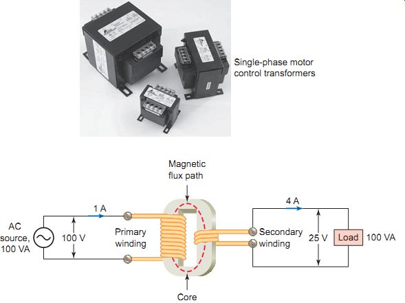
Ill.18 Simplified version of a single-phase (1ø) transformer. Single-phase
motor control transformers; AC source, 100 VA. Primary winding -- Magnetic
flux path -- Core -- Secondary winding -- Load