AMAZON multi-meters discounts AMAZON oscilloscope discounts
Goals
1. Recognize symbols frequently used on motor and control diagrams.
2. Read and construct ladder diagrams.
3. Read wiring, single-line, and block diagrams.
4. Become familiar with the terminal connections for different types of motors.
5. Interpret information found on motor nameplates.
6. Become familiar with the terminology used in motor circuits.
7. Understand the operation of manual and magnetic motor starters.
Different types of electrical drawings are used in working with motors and their control circuits. In order to facilitate making and reading electrical drawings, certain standard symbols are used.
To read electrical motor drawings, it is necessary to know both the meaning of the symbols and how the equipment operates.
This Section will help you understand the use of symbols in electrical drawings. The Section also explains motor terminology and illustrates it with practical applications.
PART 1 Symbols--Abbreviations-Ladder Diagrams
Motor Symbols
A motor control circuit can be defined as a means of supplying power to and removing power from a motor. The symbols used to represent the different components of a motor control system can be considered a type of technical shorthand.
The use of these symbols tends to make circuits diagrams less complicated and easier to read and understand.
In motor control systems, symbols and related lines show how the parts of a circuit are connected to one another. Unfortunately, not all electrical and electronic symbols are standardized. You will find slightly different symbols used by different manufacturers. Also, symbols sometimes look nothing like the real thing, so you have to learn what the symbols mean. FGR. 1 shows some of the typical symbols used in motor circuit diagrams.
Abbreviations for Motor Terms
An abbreviation is the shortened form of a word or phase. Uppercase letters are used for most abbreviations. The following is a list of some of the abbreviations commonly used in motor circuit diagrams.
AC alternating current ARM armature AUTO automatic BKR breaker COM common CR control relay CT current transformer DC direct current DB dynamic braking FLD field FWD forward GRD ground HP horsepower L1, L2, L3 power line connections LS limit switch MAN manual MTR motor M motor starter NEG negative NC normally closed NO normally open OL overload relay PH phase PL pilot light POS positive PWR power PRI primary PB push button
REC rectifier REV reverse RH rheostat SSW safety switch SEC secondary 1PH single-phase SOL solenoid SW switch T1, T2, T3 motor terminal connections 3PH three-phase TD time delay TRANS transformer
Motor Ladder Diagrams
Motor control drawings provide information on circuit operation, device and equipment location, and wiring instructions. Symbols used to represent switches consist of node points (places where circuit devices attach to each other), contact bars, and the specific symbol that identifies that particular type of switch, as illustrated in FGR. 2.
Although a control device may have more than one set of contacts, only the contacts used in the circuit are represented on control drawings.
A variety of control diagrams and drawings are used to install, maintain, and troubleshoot motor control systems. These include ladder diagrams, wiring diagrams, line diagrams, and block diagrams. A "ladder diagram" (considered by some as a form of a schematic diagram) focuses on the electrical operation of a circuit, not the physical location of a device. For example, two stop push buttons may be physically at opposite ends of a long conveyor, but electrically side by side in the ladder diagram.
Ladder diagrams, such as the one shown in FGR. 3, are drawn with two vertical lines and any number of horizontal lines. The vertical lines (called rails) connect to the power source and are identified as line 1 (L1) and line 2 (L2). The horizontal lines (called rungs) are connected across L1 and L2 and contain the control circuitry.
Ladder diagrams are designed to be read like a book, starting at the top left and reading from left to right and top to bottom.
Because ladder diagrams are easier to read, they are often used in tracing through the operation of a circuit. Most programmable logic controllers (PLCs) use the ladder-diagramming concept as the basis for their programming language.
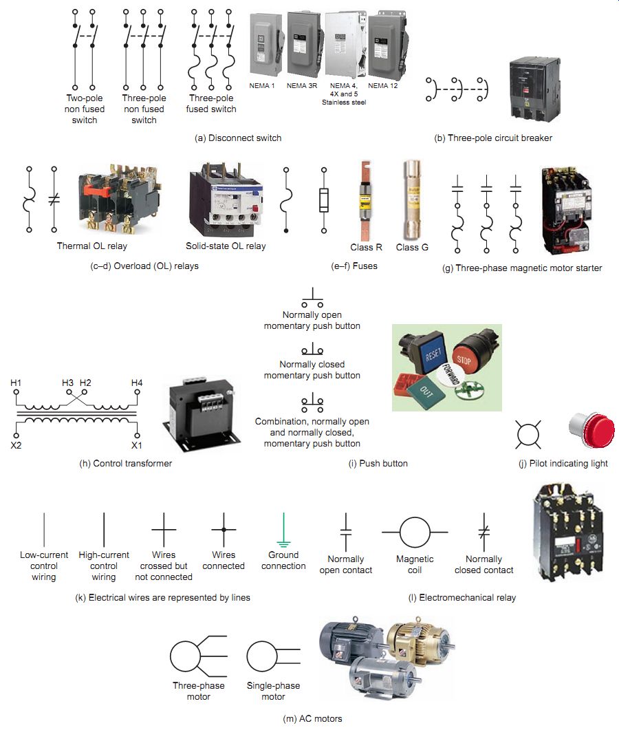
FGR. 1 Motor control symbols.
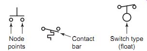
FGR. 2 Switch symbol component parts.
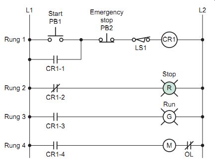
FGR. 3 Typical ladder diagram.
FGR. 4 Motor power and control circuit wiring.
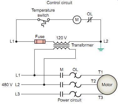
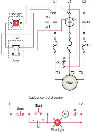
Most ladder diagrams illustrate only the single-phase control circuit connected to L1 and L2, and not the three-phase power circuit supplying the motor. FGR. 4 shows both the power circuit and control circuit wiring.
On diagrams that include power and control circuit wiring, you may see both heavy and light conductor lines. The heavy lines are used for the higher-current power circuit and the lighter lines for the lower-current control circuit.
Conductors that cross each other but make no electrical contact are represented by intersecting lines with no dot.
Conductors that make contact are represented by a dot at the junction. In most instances the control voltage is obtained directly from the power circuit or from a step down control transformer connected to the power circuit.
Using a transformer allows a lower voltage (120 V AC) for the control circuit while supplying the three-phase motor power circuit with a higher voltage (480 V AC) for more efficient motor operation.
A ladder diagram gives the necessary information for easily following the sequence of operation of the circuit.
It is a great aid in troubleshooting as it shows, in a simple way, the effect that opening or closing various contacts has on other devices in the circuit. All switches and relay contacts are classified as normally open (NO) or normally closed (NC). The positions drawn on diagrams are the electrical characteristics of each device as would be found when it is purchased and not connected in any circuit. This is sometimes referred to as the "off-the-shelf " or deenergized state. It is important to understand this because it may also represent the deenergized position in a circuit. The deenergized position refers to the component position when the circuit is deenergized, or no power is present on the circuit. This point of reference is often used as the starting point in the analysis of the operation of the circuit.
FGR. 5 Identification of coils and associated contacts.
A common method used to identify the relay coil and the contacts operated by it is to place a letter or letters in the circle that represents the coil (FGR. 5). Each contact that is operated by this coil will have the coil letter or letters written next to the symbol for the contact.
Sometimes, when there are several contacts operated by one coil, a number is added to the letter to indicate the contact number. Although there are standard meanings of these letters, most diagrams provide a key list to show what the letters mean; generally they are taken from the name of the device.
A load is a circuit component that has resistance and consumes electric power supplied from L1 to L2. Control coils, solenoids, horns, and pilot lights are examples of loads. At least one load device must be included in each rung of the ladder diagram. Without a load device, the control devices would be switching an open circuit to a short circuit between L1 and L2. Contacts from control devices such as switches, push buttons, and relays are considered to have no resistance in the closed state. Connection of contacts in parallel with a load also can result in a short circuit when the contact closes. The circuit current will take the path of least resistance through the closed contact, shorting out the energized load.
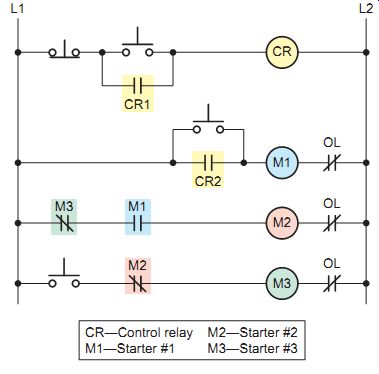
Normally loads are placed on the right side of the ladder diagram next to L2 and contacts on the left side next to L1. One exception to this rule is the placement of the normally closed contacts controlled by the motor overload protection device. These contacts are drawn on the right side of the motor starter coil as shown in FGR. 6. When two or more loads are required to be energized simultaneously, they must be connected in parallel. This will ensure that the full line voltage from L1 and L2 will appear across each load. If the loads are connected in series, neither will receive the entire line voltage necessary for proper operation. Recall that in a series connection of loads the applied voltage is divided between each of the loads. In a parallel connection of loads the voltage across each load is the same and is equal in value to the applied voltage.
Control devices such as switches, push buttons, limit switches, and pressure switches operate loads. Devices that start a load are usually connected in parallel, while devices that stop a load are connected in series. For example, multiple start push buttons controlling the same motor starter coil would be connected in parallel, while multiple stop push buttons would be connected in series (FGR. 7). All control devices are identified with the appropriate nomenclature for the device (e.g., stop, start). Similarly, all loads are required to have abbreviations to indicate the type of load (e.g., M for starter coil). Often an additional numerical suffix is used to differentiate multiple devices of the same type. For example, a control circuit with two motor starters might identify the coils as M1 (contacts 1-M1, 2-M1, etc.) and M2 (contacts 1-M2, 2-M2, etc.).
FGR. 6 Loads are placed on the right and contacts on the left.
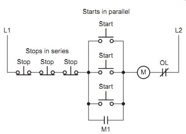
FGR. 7 Stop devices connect in series and start devices connect in parallel.
FGR. 8 Ladder diagram with rung numbers detailed.
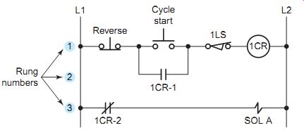
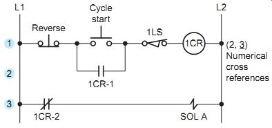
As the complexity of a control circuit increases, its ladder diagram increases in size, making it more difficult to read and locate which contacts are controlled by which coil. "Rung numbering" is used to assist in reading and understanding larger ladder diagrams. Each rung of the ladder diagram is marked (rung 1, 2, 3, etc.), starting with the top rung and reading down. A rung can be defined as a complete path from L1 to L2 that contains a load. FGR. 8 illustrates the marking of each rung in a line diagram with three separate rungs:
• The path for rung 1 is completed through the reverse push button, cycle start push button, limit switch 1LS, and coil 1CR.
• The path for rung 2 is completed through the reverse push button, relay contact 1CR-1, limit switch 1LS, and coil 1CR. Note that rung 1 and rung 2 are identified as two separate rungs even though they control the same load. The reason for this is that either the cycle start push button or the 1CR-1 relay contact completes the path from L1 to L2.
• The path for rung 3 is completed through relay contact 1CR-2 to and solenoid SOL A.
"Numerical cross-referencing" is used in conjunction with the rung numbering to locate auxiliary contacts con trolled by coils in the control circuit. At times auxiliary contacts are not in close proximity on the ladder diagram to the coil controlling their operation. To locate these contacts, rung numbers are listed to the right of L2 in parentheses on the rung of the coil controlling their operation.
In the example shown in FGR. 9:
• The contacts of coil 1CR appear at two different locations in the line diagram.
• The numbers in parentheses to the right of the line diagram identify the line location and type of contacts controlled by the coil.
• Numbers appearing in the parentheses for normally open contacts have no special markings.
• Numbers used for normally closed contacts are identified by underlining or over-scoring the number to distinguish them from normally open contacts.
• In this circuit, control relay coil 1CR controls two sets of contacts: 1CR-1 and 1CR-2. This is shown by the numerical code 2, 3.
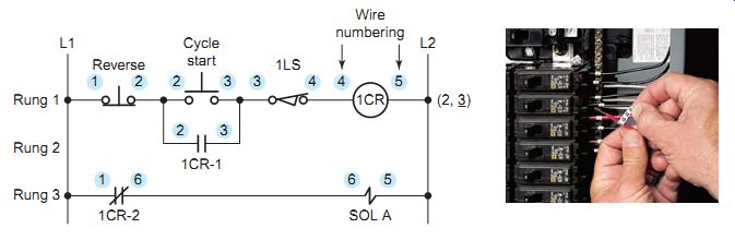
Some type of "wire identification" is required to correctly connect the control circuit conductors to their components in the circuit. The method used for wire identification varies for each manufacturer. FGR. 10 illustrates one method where each common point in the circuit is assigned a reference number:
• Numbering starts with all wires that are connected to the L1 side of the power supply identified with the number 1.
• Continuing at the top left of the diagram with rung 1, a new number is designated sequentially for each wire that crosses a component.
• Wires that are electrically common are marked with the same numbers.
• Once the first wire directly connected to L2 has been designated (in this case 5), all other wires directly connected to L2 will be marked with the same number.
• The number of components in the first line of the ladder diagram determines the wire number for conductors directly connected to L2.
FGR. 9 Numerical cross-reference system.
FGR. 10 Wire numbering.
FGR. 11 Alternative wiring identification with documentation.
FGR. 12 Representing mechanical functions.
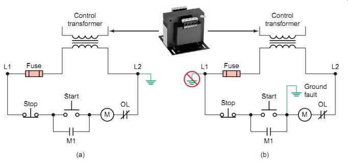
FGR. 13 Control transformer ground connection: ( a ) control transformer
properly grounded to the L2 side of the circuit; ( b ) control transformer
improperly grounded at the L1 side of the circuit.
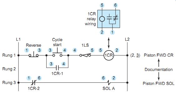
FGR. 11 illustrates an alternative method of assigning wire numbers. With this method all wires directly connected to L1 are designated 1 while all those connected to L2 are designated 2. After all the wires with 1 and 2 are marked, the remaining numbers are assigned in a sequential order starting at the top left of the diagram.
This method has as its advantage the fact that all wires directly connected to L2 are always designated as 2. Ladder diagrams may also contain a series of descriptions located to the right of L2, which are used to document the function of the circuit controlled by the output device.
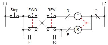
A broken line normally indicates a mechanical connection. Do not make the mistake of reading a broken line as a part of the electrical circuit. In FGR. 12 the vertical broken lines on the forward and reverse push buttons indicate that their normally closed and normally open contacts are mechanically connected. Thus, pressing the button will open the one set of contacts and close the other. The broken line between the F and R coils indicates that the two are mechanically interlocked. Therefore, coils F and R cannot close contacts simultaneously because of the mechanical interlocking action of the device.
When a control transformer is required to have one of its secondary lines grounded, the ground connection must be made so that an accidental ground in the control circuit will not start the motor or make the stop button or control inoperative. FGR. 13a illustrates the secondary of a control transformer properly grounded to the L2 side of the circuit. When the circuit is operational, the entire circuit to the left of coil M is the ungrounded circuit (it is the "hot" leg). A fault path to ground in the ungrounded circuit will create a short-circuit condition causing the control transformer fuse to open. FGR. 13b shows the same circuit improperly grounded at L1. In this case, a short to ground fault to the left of coil M would energize the coil, starting the motor unexpectedly. The fuse would not operate to open the circuit and pressing the stop but ton would not deenergize the M coil. Equipment damage and personnel injuries would be very likely. Clearly, out put devices must be directly connected to the grounded side of the circuit.
PART 1 QUIZ
1. Define what the term motor control circuit means.
2. Why are symbols used to represent components on electrical diagrams?
3. An electrical circuit contains three pilot lights. What acceptable symbol could be used to designate each light?
4. Describe the basic structure of an electrical ladder diagram schematic.
5. Lines are used to represent electrical wires on diagrams.
a. How are wires that carry high current differentiated from those that carry low current?
b. How are wires that cross but do not electrically connect differentiated from those that connect electrically?
6. The contacts of a pushbutton switch open when the button is pressed. What type of push button would this be classified as? Why?
7. A relay coil labeled TR contains three contacts.
What acceptable coding could be used to identify each of the contacts?
8. A rung on a ladder diagram requires that two loads, each rated for the full line voltage, be energized when a switch is closed. What connection of loads must be used? Why?
9. One requirement for a particular motor application is that six pressure switches be closed before the motor is allowed to operate. What connections of switches should be used?
10. The wire identification labels on several wires of an electrical panel are examined and found to have the same number. What does this mean?
11. A broken line representing a mechanical function on an electrical diagram is mistaken for a conductor and wired as such. What two types of problems could this result in?
PART 2 Wiring-Single Line-Block Diagrams
Wiring Diagrams
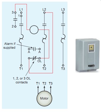
FGR. 14 Typical motor starter wiring diagram.
This material and associated copyrights are proprietary to, and used with the permission of Schneider Electric.
Wiring diagrams are used to show the point-to-point wiring between components of an electric system and sometimes their physical relation to each other. They may include wire identification numbers assigned to conductors in the ladder diagram and/or color coding. Coils, contacts, motors, and the like are shown in the actual position that would be found on an installation. These diagrams are helpful in wiring up systems, because connections can be made exactly as they are shown on the diagram. A wiring diagram gives the necessary information for actually wiring up a device or group of devices or for physically tracing wires in troubleshooting. How ever, it is difficult to determine circuit operation from this type of drawing.
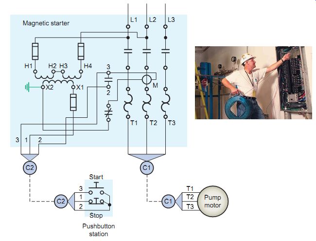
FGR. 15 Routing of wires in cables and conduits.
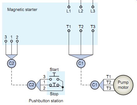
FGR. 16 Wiring with the internal connections of the magnetic starter
omitted.
Wiring diagrams are provided for most electrical devices. FGR. 14 illustrates a typical wiring diagram provided for a motor starter. The diagram shows, as closely as possible, the actual location of all of the component parts of the device. The open terminals (marked by an open circle) and arrows represent connections made by the user. Note that bold lines denote the power circuit, and thinner lines are used to show the control circuit.
The routing of wires in cables and conduits, as illustrated in FGR. 15, is an important part of a wiring diagram. A conduit layout diagram indicates the start and the finish of the electrical conduits and shows the approximate path taken by any conduit in progressing from one point to another. Integrated with a drawing of this nature is the conduit and cable schedule, which tabulates each conduit as to number, size, function, and service and also includes the number and size of wires to be run in the conduit.
Wiring diagrams show the details of actual connections. Rarely do they attempt to show complete details of panel board or equipment wiring. The wiring diagram of FGR. 15, reduced to a simpler form, is shown in FGR. 16 with the internal connections of the magnetic starter omitted. Wires encased in conduit C1 are part of the power circuit and sized for the current requirement of the motor. Wires encased in conduit C2 are part of the lower-voltage control circuit and sized to the current requirements of the control transformer.
FGR. 17 Combination wiring and ladder diagram.
FGR. 18 Single-line diagram of a motor installation.
FGR. 19 Single-line diagram of a power distribution system.
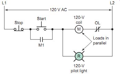
Wiring diagrams are often used in conjunction with ladder diagrams to simplify understanding of the control pro cess. An example of this is illustrated in FGR. 17. The wiring diagram shows both the power and control circuits.
A separate ladder diagram of the control circuit is included to give a clearer understanding of its operation. By following the ladder diagram it can be seen that the pilot light is wired so that it will be on whenever the starter is energized.
The power circuit has been omitted for clarity, since it can be traced readily on the wiring diagram (heavy lines).
Single-Line Diagrams
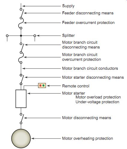
A single-line (also called a one-line) diagram uses symbols along with a single line to show all major components of an electric circuit. Some motor control equipment manufacturers use a single-line drawing, like the one shown in FGR. 18, as a road map in the study of motor control installations. The installation is reduced to the simplest possible form, yet it still shows the essential requirements and equipment in the circuit.
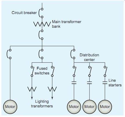
Power systems are extremely complicated electrical networks that may be geographically spread over very large areas. For the most part, they are also three-phase networks-each power circuit consists of three conductors and all devices such as generators, transformers, breakers, and disconnects etc. installed in all three phases. These systems can be so complex that a complete conventional diagram showing all the connections is impractical. When this is the case, use of a single-line diagram is a concise way of communicating the basic arrangement of the power system's component. FGR. 19 shows a single-line diagram of a small power distribution system. These types of diagrams are also called "power riser" diagrams.
Block Diagrams
A block diagram represents the major functional parts of complex electrical/electronic systems by blocks rather than symbols. Individual components and wires are not shown. Instead, each block represents electrical circuits that perform specific functions in the system. The functions the circuits perform are written in each block.
Arrows connecting the blocks indicate the general direction of current paths.
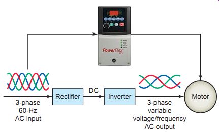
FGR. 20 shows a block diagram of a variable-frequency AC motor drive. A variable-frequency drive controls the speed of an AC motor by varying the frequency supplied to the motor. The drive also regulates the output voltage in proportion to the output frequency to provide a relatively constant ratio (volts per hertz; V/Hz) of voltage to frequency, as required by the characteristics of the AC motor to produce adequate torque. The function of each block is summarized as follows:
• 60-Hz three-phase power is supplied to the rectifier block.
• The rectifier block is a circuit that converts or rectifies its three-phase AC voltage into a DC voltage.
• The inverter block is a circuit that inverts, or converts, its DC input voltage back into an AC voltage.
The inverter is made up of electronic switches, which switch the DC voltage on and off to produce a controllable AC power output at the desired frequency and voltage.
FGR. 20 Block diagram of a variable-frequency AC drive.
PART 2 QUIZ
1. What is the main purpose of a wiring diagram?
2. In addition to numbers, what other method can be used to identify wires on a wiring diagram?
3. What role can a wiring diagram play in the trouble shooting of a motor control circuit?
4. List the pieces of information most likely to be found in the conduit and cable schedule for a motor installation.
5. Explain the purpose of using a motor wiring diagram in conjunction with a ladder diagram of the control circuit.
6. What is the main purpose of a single-line diagram?
7. What is the main purpose of a block diagram?
8. Explain the function of the rectifier and inverter blocks of a variable-frequency AC drive.
PART 3 Motor Terminal Connections
Motor Classification
Electric motors have been an important element of our industrial and commercial economy for over a century.
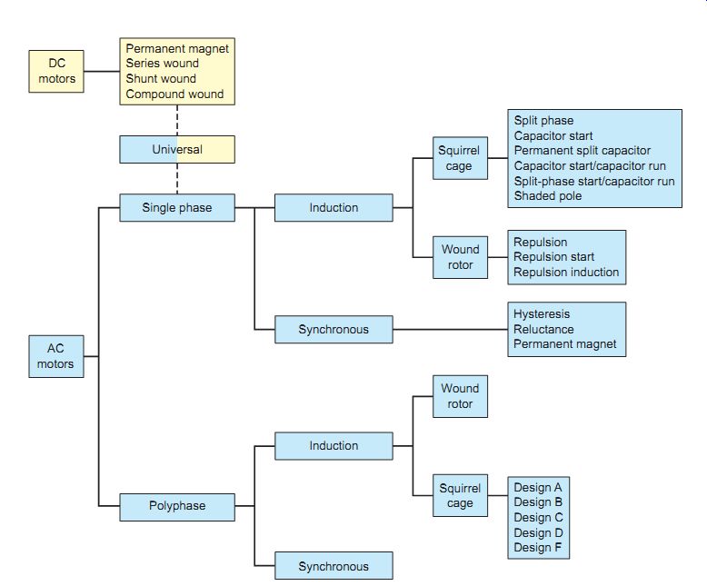
Most of the industrial machines in use today are driven by electric motors. Industries would cease to function with out properly designed, installed, and maintained motor control systems. In general, motors are classified according to the type of power used (AC or DC) and the motor's principle of operation. The "family tree" of motor types is quite extensive, as depicted at top of the next page:
In the United States the Institute of Electrical and Electronics Engineers (IEEE) establishes the standards for motor testing and test methodologies, while the National Electrical Manufacturers Association (NEMA) prepares the standards for motor performance and classifications.
Additionally, motors shall be installed in accordance with Article 430 of the National Electrical Code (NEC).
DC Motor Connections
Industrial applications use DC motors because the speed- torque relationship can be easily varied. DC motors feature a speed, which can be controlled smoothly down to zero, immediately followed by acceleration in the opposite direction. In emergency situations, DC motors can supply over five times rated torque without stalling. Dynamic braking (DC motor-generated energy is fed to a resistor grid) or regenerative braking (DC motor-generated energy is fed back into the DC motor supply) can be obtained with DC motors on applications requiring quick stops, thus eliminating the need for, or reducing the size of, a mechanical brake.
FGR. 21 shows the symbols used to identify the basic parts of a direct current (DC) compound motor.
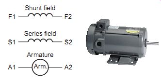
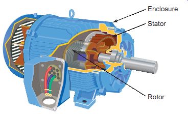
FGR. 21 Parts of a DC compound motor.
The rotating part of the motor is referred to as the armature; the stationary part of the motor is referred to as the stator, which contains the series field winding and the shunt field winding. In DC machines A1 and A2 always indicate the armature leads, S1 and S2 indicate the series field leads, and Fl and F2 indicate the shunt field leads.
It is the kind of field excitation provided by the field that distinguishes one type of DC motor from another; the construction of the armature has nothing to do with the motor classification. There are three general types of DC motors, classified according to the method of field excitation as follows:
• A shunt DC motor (FGR. 22) uses a comparatively high resistance shunt field winding, made up of many turns of fine wire, connected in parallel (shunt) with the armature.
• A series DC motor (FGR. 23) uses a very low resistance series field winding, made up of very few turns of heavy wire, connected in series with the armature.
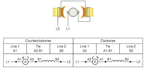
• A compound DC motor (FGR. 24) uses a combination of a shunt field (many turns of fine wire) in parallel with the armature, and series field (few turns of heavy wire) in series with the armature.
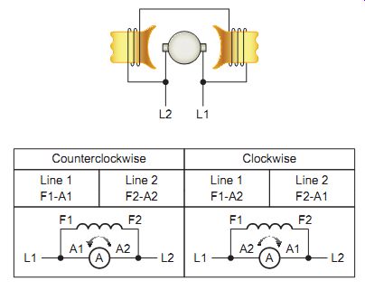
FGR. 22 Standard DC shunt motor connections for counterclockwise and
clockwise rotation.
FGR. 23 Standard DC series motor connections for counterclockwise and
clockwise rotation.
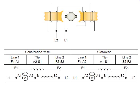
FGR. 24 Standard DC compound (cumulative) motor connections for counterclock
wise and clockwise rotation. For differential compound connection, reverse
S1 and S2.
All connections shown in Figures 22, 23, and 24 are for counterclockwise and clockwise rotation facing the end opposite the drive (commutator end). One purpose of applying markings to the terminals of motors according to a standard is to aid in making connections when a predict able rotation direction is required. This may be the case when improper rotation could result in unsafe operation or damage. Terminal markings are normally used to tag only those terminals to which connections must be made from outside circuits.
The direction of rotation of a DC motor depends on the direction of the magnetic field and the direction of current flow in the armature. If either the direction of the field or the direction of current flow through the armature is reversed, the rotation of the motor will reverse. However, if both of these factors are reversed at the same time, the motor will continue rotating in the same direction.
AC Motor Connections
The AC induction motor is the dominant motor technology in use today, representing more than 90 percent of installed motor capacity. Induction motors are available in single-phase (1?) and three-phase (3?) configurations, in sizes ranging from fractions of a horsepower to tens of thousands of horsepower. They may run at fixed speeds- most commonly 900, 1200, 1800, or 3600 rpm-or be equipped with an adjustable-speed drive.
The most commonly used AC motors by far have a squirrel-cage configuration (FGR. 25), so named because of the aluminum or copper squirrel cage imbedded within the iron laminates of the rotor. There is no physical electrical connection to the squirrel cage. Current in the rotor is induced by the rotating magnetic field of the stator.
Wound-rotor models, in which coils of wire turn the rotor windings, are also available. These are expensive but offer greater control of the motor's performance characteristics, so they are most often used for special torque and acceleration applications and for adjustable-speed applications.
FGR. 25 Three-phase squirrel-cage AC induction motor.
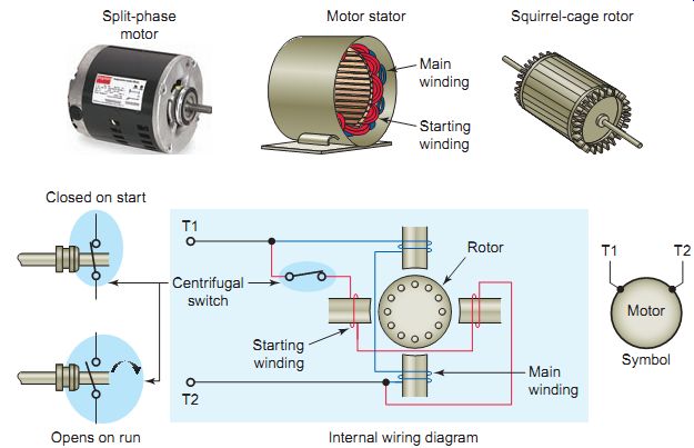
FGR. 26 AC split-phase induction motor.
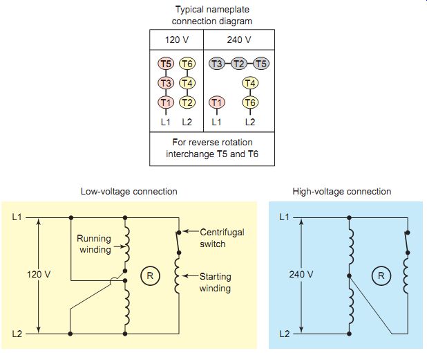
FGR. 27 Dual-voltage split-phase motor stator connections.
SINGLE-PHASE MOTOR CONNECTIONS
The majority of single-phase AC induction motors are constructed in fractional horsepower sizes for 120- to 240-V, 60-Hz power sources. Although there are several types of single-phase motors they are basically identical except for the means of starting. The "split-phase motor" is most widely used for medium starting applications ( FGR. 26). The operation of the split-motor is summarized as follows:
• The motor has a start and main, or run, winding which are both energized when the motor is started.
• The starting winding produces a phase difference to start the motor and is switched out by a centrifugal switch as running speed is approached. When the motor reaches about 75 percent of its rated full load speed, the starting winding is disconnected from the circuit.
• Split-phase motor sizes range up to about ½ horse power. Popular applications include fans, blowers, home appliances such as washers and dryers, and tools such as small saws or drill presses where the load is applied after the motor has obtained its operating speed.
• The motor can be reversed by reversing the leads to the starting winding or main winding, but not to both. Generally the industry standard is to reverse the start winding leads
In a dual-voltage split-phase motor (FGR. 27), the running winding is split into two sections and can be connected to operate from a 120-Volt or 240-V source. The two run windings are connected in series when operated from a 240-V source, and in parallel for 120-V operation.
The start winding is connected across the supply lines for low voltage and at one line to the midpoint of the run windings for high voltage. This ensures that all windings receive the 120 V they are designed to operate at. To reverse the direction of rotation of a dual-voltage split phase motor, interchange the two start winding leads.
Dual-voltage motors are connected for the desired voltage by following the connection diagram on the nameplate.
The nominal dual-voltage split-phase motor rating is 120/240 V. With any type of dual-voltage motor, the higher voltage is preferred when a choice between voltages is avail able. The motor uses the same amount of power and produces the same amount of horsepower when operating from a 120-V or 240-V supply. However, as the voltage is doubled from 120 V to 240 V, the current is cut in half. Operating the motor at this reduced current level allows you to use smaller circuit conductors and reduces line power losses.
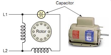
FGR. 28 Permanent-split capacitor motor.
Many single-phase motors use a capacitor in series with one of the stator windings to optimize the phase difference between the start and run windings for starting. The result is a higher starting torque than a split-phase motor can produce. There are three types of capacitor motors: capacitor start , in which the capacitor phase is in the circuit only during starting; permanent-split capacitor , in which the capacitor phases in the circuit for both starting and running; and two-value capacitor , in which there are different values of capacitance for starting and running. The permanent-split capacitor motor, illustrated in FGR. 28, uses a capacitor permanently connected in series with one of the stator windings. This design is lower in cost than the capacitor-start motors that incorporate capacitor switching systems. Installations include compressors, pumps, machine tools, air conditioners, conveyors, blowers, fans, and other hard-to-start applications.
THREE-PHASE MOTOR CONNECTIONS
The three-phase AC induction motor is the most common motor used in commercial and industrial applications.
Single-phase larger horsepower motors are not normally used because they are inefficient compared to three-phase motors. In addition, single-phase motors are not self- starting on their running windings, as are three-phase motors.
Large horsepower AC motors are usually three-phase.
All three-phase motors are constructed internally with a number of individually wound coils. Regardless of how many individual coils there are, the individual coils will always be wired together (series or parallel) to produce three distinct windings, which are referred to as phase A, phase B, and phase C. All three-phase motors are wired so that the phases are connected in either wye (Y) or delta (?) configuration, as illustrated in FGR. 29.
DUAL-VOLTAGE MOTOR CONNECTIONS
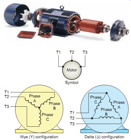
FGR. 29 Three-phase wye and delta motor connections.
It is common practice to manufacture three-phase motors that can be connected to operate at different voltage levels.
The most common multiple-voltage rating for three-phase motors is 208/230/460 V. Always check the motor specifications or nameplate for the proper voltage rating and wiring diagram for method of connection to the voltage source.
FGR. 30 illustrates the typical terminal identification and connection table for a nine-lead dual-voltage wye-connected three-phase motor. One end of each phase is internally permanently connected to the other phases.
Each phase coil (A, B, C) is divided into two equal parts and connected in either series for high-voltage operation or parallel for low-voltage operation. According to NEMA nomenclature, these leads are marked T1 through T9. High-voltage and low-voltage connections are given in the accompanying connection table and motor terminal board. The same principle of series (high-voltage) and parallel (low-voltage) coil connections is applied for dual voltage wye-delta connected three-phase motors. In all cases refer to the wiring diagram supplied with the motor to ensure proper connection for the desired voltage level.
Cont. to part 2 >>