AMAZON multi-meters discounts AMAZON oscilloscope discounts
cont. from part 1
Grounding - Lockout - Codes
Grounding and Bonding
Proper grounding practices protect people from the hazards of electric shock and ensure the correct operation of overcurrent protection devices. Intentional grounding is required for the safe operation of electrical systems and equipment. Unintentional or accidental grounding is considered a fault in electrical wiring systems or circuits.
"Grounding" is the intentional connection of a current carrying conductor to the earth. For AC premises wiring systems in buildings and similar structures, this ground connection is made on the line side of the service equipment and the supply source, such as a utility transformer.
The prime reasons for grounding are:
• To limit the voltage surges caused by lightning, utility system operations, or accidental contact with higher-voltage lines.
• To provide a ground reference that stabilizes the voltage under normal operating conditions.
• To facilitate the operation of overcurrent devices such as circuit breakers, fuses, and relays under ground-fault conditions.
"Bonding" is the permanent joining together of metal parts that aren't intended to carry current during normal operation, which creates an electrically conductive path that can safely carry current under ground-fault conditions. The prime reasons for bonding are:
• To establish an effective path for fault current that facilitates the operation of overcurrent protective devices.
• To minimize shock hazard to people by providing a low-impedance path to ground. Bonding limits the touch voltage when non-current-carrying metal parts are inadvertently energized by a ground fault.
--
Ground-fault current path: Utility transformer; Ground fault current; Earth; Service equipment; Main bonding jumper; Path through earth not acceptable for ground path because of high impedance; Grounding electrode conductor; Earth grounding electrode; Ground fault to metal conduit; Motor
--
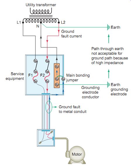
Ill. 7 Ground-fault current path
The Code requires all metal used in the construction of a wiring system to be bonded to, or connected to, the ground system. The intent is to provide a low-impedance path back to the utility transformer in order to quickly clear faults. Ill. 7 illustrates the ground-fault current path required to ensure that overcurrent devices operate to open the circuit. The earth isn't considered an effective ground-fault current path. The resistance of earth is so high that very little fault current returns to the electrical supply source through the earth. For this reason the main bonding jumper is used to provide the connection between the grounded service conductor and the equipment grounding conductor at the service. Bonding jumpers may be located throughout the electrical system, but a main bonding jumper is located only at the service.
Grounding is accomplished by connecting the circuit to a metal underground water pipe, the metal frame of a building, a concrete-encased electrode, or a ground ring.
A grounding system has two distinct parts: system grounding and equipment grounding. System grounding is the electrical connection of one of the current carrying conductors of the electrical system to the ground.
Equipment grounding is the electrical connection of all the metal parts that don't carry current of all electrical equipment to the ground. Conductors that form parts of the grounding system include the following:
Equipment grounding conductor (EGC) is an electrical conductor that provides a low-impedance ground path between electrical equipment and enclosures within the distribution system. Ill. 8 shows the connection for an EGC. Electrical motor windings are normally insulated from all exposed non-current carrying metal parts of the motor. However, if the insulation system should fail, then the motor frame could become energized at line voltage. Any person contacting a grounded surface and the energized motor frame simultaneously could be severely injured or killed. Effectively grounding the motor frame forces it to take the same zero potential as the earth, thus preventing this possibility.
Grounded conductor is a conductor that has been intentionally grounded.
Grounding electrode conductor is a conductor used to connect the equipment grounding conductor or the grounded conductor (at the service or at the separately derived system) to the grounding electrode(s).
--
Equipment grounding conductor (EGC): Equipment grounding conductor (EGC)' Circuit breaker; Overload protection; Controller
--
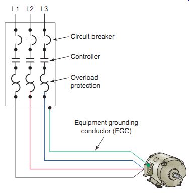
Ill. 8 Equipment grounding conductor (EGC).
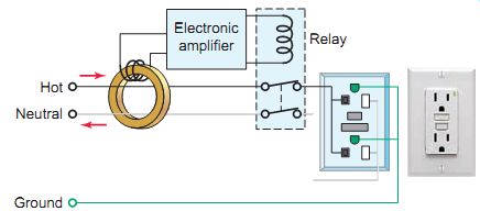
Ill. 9 GFCI receptacle.
A separately derived system is a system that supplies electrical power derived (taken) from a source other than a service, such as the secondary of a distribution transformer.
A ground fault is defined as an unintentional, electrically conducting connection between an ungrounded conductor of an electric circuit and the normally non current-carrying conductors, metallic enclosures, metallic raceways, metallic equipment, or earth. The ground-fault circuit interrupter (GFCI) is a device that can sense small ground-fault currents. The GFCI is fast acting; the unit will shut off the current or interrupt the circuit within 1/40 second after its sensor detects a leakage as small as 5 milliamperes (mA). Most circuits are protected against overcurrent by 15 ampere or larger fuses or circuit breakers. This protection is adequate against short circuits and overloads. Leakage currents to ground may be much less than 15 amperes and still be hazardous.
Ill. 9 shows the simplified circuit of a GFCI receptacle. The device compares the amount of current in the ungrounded (hot) conductor with the amount of current in the grounded (neutral) conductor. Under normal operating conditions, the two will be equal in value. If the cur rent in the neutral conductor becomes less than the current in the hot conductor, a ground-fault condition exists. The amount of current that's missing is returned to the source by the ground-fault path. Whenever the ground-fault cur rent exceeds approximately 5 mA the device automatically opens the circuit to the receptacle.
GFCIs can be used successfully to reduce electrical hazards on construction sites. The ground-fault protection rules and regulations of OSHA have been determined necessary and appropriate for employee safety and health.
According to OSHA, it's the employer's responsibility to provide either: (1) ground-fault circuit interrupters on construction sites for receptacle outlets in use and not part of the permanent wiring of the building or structure, or (2) a scheduled and recorded assured equipment-grounding conductor program on construction sites, covering all cord sets, receptacles that are not part of the permanent wiring of the building or structure, and equipment connected by cord and plug that are available for use or used by employees.
- GFCI receptacle. :Hot; Neutral; Ground; Electronic amplifier; relay
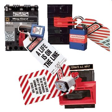
Ill. 10 Lockout/tagout devices.
--
Lockout / Tagout
Electrical "lockout" is the process of removing the source of electrical power and installing a lock, which prevents the power from being turned ON. Electrical "tagout" is the process of placing a danger tag on the source of electrical power, which indicates that the equipment may not be operated until the danger tag is removed (Ill. 10). This procedure is necessary for the safety of personnel in that it ensures that no one will inadvertently energize the equipment while it's being worked on. Electrical lock out and tagout is used servicing electrical equipment that does not require power to be on to perform the service as in the case of motor alignment or replacement of a motor or motor control component.
Lockout means achieving a zero state of energy while equipment is being serviced. Just pressing a stop button to shut down machinery won't provide you with security.
Someone else working in the area can simply reset it.
Even a separate automated control could be activated to override the manual controls. It's essential that all inter locking or dependent systems also be deactivated. These could feed into the system being isolated, either mechanically or electrically. It's important to test the start button before resuming any work in order to verify that all possible energy sources have been isolated.
The "danger tag" has the same importance and purpose as a lock and is used alone only when a lock does not fit the disconnect means. Danger tags are required to be securely attached at the disconnect device with space pro vided for the worker's name, craft, and procedure that's taking place.
The following are the basic steps in a lockout procedure:
• Prepare for machinery shutdown: Document all lockout procedures in a plant safety manual.
This manual should be available to all employees and outside contractors working on the premises.
Management should have policies and procedures for safe lockout and should also educate and train everyone involved in locking out electrical or mechanical equipment. Identify the location of all switches, power sources, controls, interlocks, and other devices that need to be locked out in order to isolate the system.
• Machinery or equipment shutdown: Stop all running equipment by using the controls at or near the machine.
• Machinery or equipment isolation: Disconnect the switch (don't operate if the switch is still under load). Stand clear of the box and face away while operating the switch with the left hand (if the switch is on the right side of the box).
• Lockout and tagout application: Lock the disconnect switch in the OFF position. If the switch box is the breaker type, make sure the locking bar goes right through the switch itself and not just the box cover. Some switch boxes contain fuses, and these should be removed as part of the lockout process.
If this is the case, use a fuse puller to remove them.
--
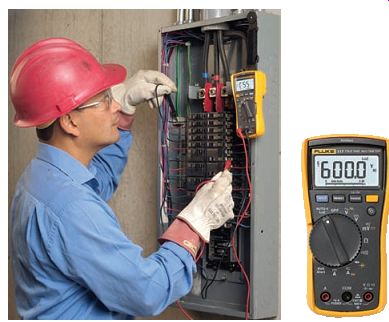
Ill. 11 Testing for the presence of voltage, using a DMM.
--
Use a tamper-proof lock with one key, which is kept by the individual who owns the lock. Combination locks, locks with master keys, and locks with duplicate keys are not recommended.
Tag the lock with the signature of the individual performing the repair and the date and time of the repair. There may be several locks and tags on the disconnect switch if more than one person is working on the machinery. The machine operator's (and/ or the maintenance operator's) lock and tag will be present as well as the supervisor's.
• Release of stored energy: All sources of energy that have the potential to unexpectedly start up, energize, or release must be identified and locked, blocked, or released.
• Verification of isolation: Use a voltage test to determine that voltage is present at the line side of the switch or breaker. When all phases of outlet are dead with the line side live, you can verify the isolation. Ensure that your voltmeter is working properly by performing the "live-dead-live" check before each use: First check your voltmeter on a known live voltage source of the same voltage range as the circuit you will be working on. Next check for the presence of voltage on the equipment you have locked out. Finally, to ensure that your voltmeter did not malfunction, check it again on the known live source.
• Lockout/tagout removal: Remove tags and locks when the work is completed. Each individual must remove his or her own lock and tag. If there is more than one lock present, the person in charge of the work is the last to remove his or her lock. Before reconnecting the power, check that all guards are in place and that all tools, blocks, and braces used in the repair are removed. Make sure that all employees stand clear of the machinery.
Electrical Codes and Standards
OCCUPATIONAL SAFETY AND HEALTH ADMINISTRATION (OSHA)
In 1970, Congress created a regulatory agency known as the Occupational Safety and Health Administration (OSHA). The purpose of OSHA is to assure safe and healthful working conditions for working men and women by authorizing enforcement of standards developed under the Act, by encouraging and assisting state governments to improve and expand their own occupational safety and health programs, and by providing for research, information, education, and training in the field of occupational health and safety.
OSHA inspectors check on companies to make sure they are following prescribed safety regulations. OSHA also inspects and approves safety products. OSHA's electrical standards are designed to protect employees exposed to dangers such as electric shock, electrocution, fires, and explosions.
--
Ill. 12
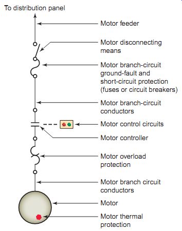
Motor terminology: To distribution panel Motor feeder, Motor branch-circuit ground-fault and short-circuit protection (fuses or circuit breakers), Motor disconnecting means, Motor branch-circuit conductors, Motor controller, Motor overload protection, Motor, Motor thermal protection, Motor branch circuit conductors, Motor control circuits
--
NATIONAL ELECTRICAL CODE (NEC)
The National Electrical Code (NEC) comprises a set of rules that, when properly applied, are intended to provide a safe installation of electrical wiring and equipment. This widely adopted minimum electrical safety standard has as its primary purpose "the practical safeguarding of persons and property from hazards arising from the use of electricity." Standards contained in the NEC are enforced by being incorporated into the different city and community ordinances that deal with electrical installations in residences, industrial plants, and commercial buildings. The NEC is the most widely adopted code in the world and many jurisdictions adopt it in its entirety without exception or local amendments or supplements.
An "Article" of the Code covers a specific subject.
E.g., Article 430 of the NEC covers motors and all associated branch circuits, overcurrent protection, overload, and so on. The installation of motor-control centers is covered in Article 408, and air-conditioning equipment is covered in Article 440. Each Code rule is called a "Code Section." A Code Section may be broken down into subsections. E.g., the rule that requires a motor disconnecting means be mounted within sight of the motor and driven machinery is contained in Section 430.102 (B). "In sight" is defined by the Code as visible and not more than 50 feet in distance (Article 100-definitions).
Article 430 on motors is the longest article in the Code. One of the reasons for this is that the characteristics of a motor load are quite different from heating or incandescent lighting loads and so the method of protecting branch circuit conductors against excessive cur rent is slightly different. Non-motor branch circuits are protected against overcurrent, whereas motor branch circuits are protected against overload conditions as well as ground-faults and short circuits. The single-line diagram of Ill. 12 illustrates some of the motor terminology used throughout the Code and by motor control equipment manufacturers.
The use of electrical equipment in hazardous locations increases the risk of fire or explosion. Hazardous locations can contain gas, dust (e.g., grain, metal, wood, or coal), or flying fibers (textiles or wood products). A substantial part of the NEC is devoted to the discussion of hazardous locations, because electrical equipment can become a source of ignition in these volatile areas. Articles 500 through 504 and 510 through 517 provide classification and installation standards for the use of electrical equipment in these locations. Explosion-proof apparatus, dust ignition-proof equipment, and purged and pressurized equipment are examples of protection techniques that can be used in certain hazardous (classified) locations.
Ill. 13 shows a motor start/stop station designed to meet hazardous location requirements.
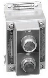
--Ill. 13 Push button station designed for hazardous locations.--
NATIONAL FIRE PROTECTION ASSOCIATION (NFPA)
The National Fire Protection Association (NFPA) develops codes governing construction practices in the building and electrical trades. It is the world's largest and most influential fire safety organization. NFPA has published almost 300 codes and standards, including the National Electrical Code, with the mission of preventing the loss of life and property. Fire prevention is a very important part of any safety program. Ill. 14 illustrates some of the common types of fire extinguishers and their applications.
Icons found on the fire extinguisher indicate the types of fire the unit's intended to be used on.
It is important to know where your fire extinguishers are located and how to use them. In case of an electrical fire the following procedures should be followed:
1. Trigger the nearest fire alarm to alert all personnel in the workplace as well as the fire department.
2. If possible, disconnect the electric power source.
3. Use a carbon dioxide or dry-powder fire extinguisher to put out the fire. Under no circumstances use water, as the stream of water may conduct electricity through your body and give you a severe shock.
4. Ensure that all persons leave the danger area in an orderly fashion.
5. Don't reenter the premises unless advised to do so.
There are four classes of fires, categorized according to the kind of material that's burning (see Ill. 14):
• Class A fires are those fueled by materials that, when they burn, leave a residue in the form of ash, such as paper, wood, cloth, rubber, and certain plastics.
• Class B fires involve flammable liquids and gases, such as gasoline, paint thinner, kitchen grease, propane, and acetylene.
• Class C fires involve energized electrical wiring or equipment such as motors and panel boxes.
• Class D fires involve combustible metals such as magnesium, titanium, zirconium, sodium, and potassium.
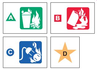
Ill.14 Types of fire extinguishers and their applications.
Ill. 14 NATIONALLY RECOGNIZED TESTING LABORATORY (NRTL)
Article 100 of the NEC defines the terms "labeled" and "listed," which are both related with product evaluation.
Labeled or listed indicates the piece of electrical equipment or material has been tested and evaluated for the purpose for which it's intended to be used. Products that are big enough to carry a label are usually labeled. The smaller products are usually listed. Any modification of a piece of electrical equipment in the field may void the label or listing.
In accordance with OSHA Safety Standards, a Nation ally Recognized Testing Laboratory (NRTL) must test electrical products for conformity to national codes and standards before they can be listed or labeled. The biggest and best-known testing laboratory is the Underwriters' Laboratories, identified with the UL logo shown in Ill. 15. The purpose of the Underwriters' Laboratories is to establish, maintain, and operate laboratories for the investigation of materials, devices, products, equipment, construction, methods, and systems with regard to hazards affecting life and property.

Underwriters' Laboratories
logo.
NATIONAL ELECTRICAL MANUFACTURERS ASSOCIATION (NEMA)
The National Electrical Manufacturers Association (NEMA) is a group that defines and recommends safety standards for electrical equipment. Standards established by NEMA assist users in proper selection of industrial control equipment. As an example, NEMA standards pro vide practical information concerning the rating, testing, performance, and manufacture of motor control devices such as enclosures, contactors, and starters.
INTERNATIONAL ELECTROTECHNICAL COMMISSION (IEC)
The International Electrotechnical Commission (IEC) is a Europe-based organization made up of national commit tees from over 60 countries. There are basically two major mechanical and electrical standards for motors: NEMA in North America and IEC in most of the rest of the world.
Dimensionally, IEC standards are expressed in metric units. Though NEMA and IEC standards use different units of measurements and terms, they are essentially analogous in ratings and , for most common applications, are largely interchangeable. NEMA standards tend to be more conservative-allowing more room for "design interpretation," as has been U.S. practice. Conversely, IEC standards tend to be more specific, more categorized some say more precise-and designed with less overload capacity. As an example, a NEMA-rated motor starter will typically be larger than its IEC counterpart.
INSTITUTE OF ELECTRICAL AND ELECTRONICS ENGINEERS (IEEE)
The Institute of Electrical and Electronics Engineers (IEEE) is a technical professional association whose primary goal is to foster and establish technical developments and advancements in electrical and electronic standards. IEEE is a leading authority in technical areas. Through its technical publishing, conferences, and consensus-based standards activities, the IEEE produces more than 30 percent of the world's published literature in electrical and electronic engineering. E.g., IEEE Standard 142 provides all the information you need for a good grounding design.
QUIZ
1. Explain how grounding the frame of a motor can prevent someone from receiving an electric shock.
2. Compare the terms grounding and bonding.
3. What is the minimum amount of leakage ground current required to trip a ground-fault circuit interrupter?
4. List the seven steps involved in a lockout/tagout procedure.
5. A disconnect switch is to be pulled open as part of a lockout procedure. Explain the safe way to proceed.
6. What is the prime objective of the National Electrical Code?
7. How are the standards contained in the NEC enforced?
8. Explain the difference between a Code Article and a Section.
9. What do the icons found on most fire extinguishers indicate?
10. What does a UL-labeled or -listed electrical device signify?
11. List three motor control devices that are rated by NEMA.
12. Compare NEMA and IEC motor standards.
Examples of Troubleshooting:
1. The voltage between the frame of a 3-phase 208-V motor and a grounded metal pipe is measured and found to be 120-V. What does this indicate? Why?
2. A ground-fault circuit interrupter does not provide overload protection. Why?
3. A listed piece of electrical equipment isn't installed according to the manufacturer's instructions. Discuss why this will void the listing.
4. A hot stick is to be used to open a manually operated high-voltage disconnect switch. Why is it important to make certain that no loads are connected to the circuit when the switch is opened?
IMPORTANT DISCUSSION TOPICS and CRITICAL THINKING:
1. Worker A makes contact with a live wire and receives a mild shock. Worker B makes con tact with the same live wire and receives a fatal shock. Discuss some of the reasons why this might occur.
2. The victim of death by electrocution is found with his fist still clenched firmly around the live conductor he made contact with. What does this indicate?
3. Why can birds safely rest on high-voltage power lines without getting shocked?
4. You have been assigned the task of explaining the company lockout procedure to new employees.
Outline what you would consider the most effective way of doing this.
5. Visit the website of one of the groups involved with electrical codes and standards. Report on the service it provides.