AMAZON multi-meters discounts AMAZON oscilloscope discounts
cont. from part 1
Sensors
Sensors are devices that are used to detect, and often to measure, the magnitude of something. They basically operate by converting mechanical, magnetic, thermal, optical, and chemical variations into electric voltages and currents. Sensors are usually categorized by what they measure, and play an important role in modern manufacturing process control. Typical applications for sensors are illustrated in Ill. 26 and include light sensor, pressure sensor, and bar code sensor.
Proximity Sensors
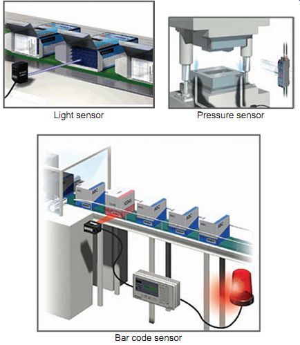
Ill. 26 Typical sensor applications. Light sensor; Pressure sensor;
Bar code sensor
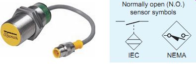
Ill. 27 Proximity sensor and symbols. Normally open (N.O.) sensor symbols
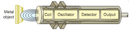
Ill. 28 Inductive proximity sensor. Metal object; Coil; Oscillator;
Detector Output
Proximity sensors detect the presence of an object (usually called the target) without physical contact. Detection of the presence of solids such as metal, glass, and plastics, as well as most liquids, is achieved by means of a sensing magnetic or electrostatic field. These electronic sensors are completely encapsulated to protect against excessive vibration, liquids, chemicals, and corrosive agents found in the industrial environment.
Proximity sensors are available in various sizes and con figurations to meet different application requirements. One of the most common configurations is the barrel type, which houses the sensor in a metal or polymer barrel with threads on the outside of the housing Ill. 27 shows a barrel type proximity switch along with the symbols used to represent it.
The threaded housing allows the sensor to be easily adjusted on a mounting frame.
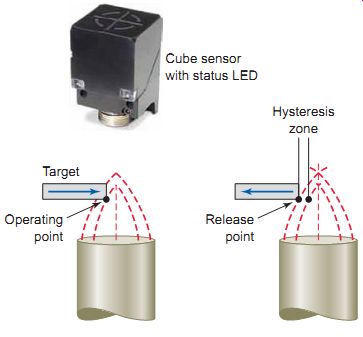
Ill. 29 Proximity sensor sensing range.
Hysteresis zone Cube sensor with status LED Target Operating point Release point
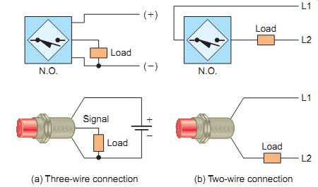
Ill. 30 Typical two-wire and three-wire sensor connections. (a) Three-wire
connection (b) Two-wire connection
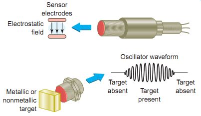
Ill. 31 Capacitive proximity sensor. Sensor electrodes; Electrostatic
field; Oscillator waveform; Target present; Target absent; Target absent;
Metallic or nonmetallic target
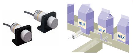
Ill. 32 Capacitive proximity sensor liquid detection. Omron Industrial
Automation, www.ia.omron.com.
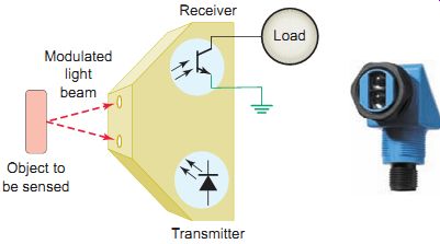
Ill. 33 Photoelectric sensor. SICK Inc., www.sick.com. Modulated light
beam; Load; Transmitter; Receiver; Object to be sensed
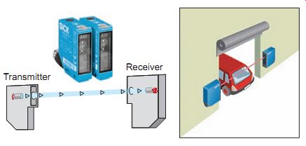
Ill. 34 Through-beam scan. SICK, Inc., www.sick.com. Transmitter; Receiver
INDUCTIVE PROXIMITY SENSORS
Proximity sensors operate on different principles, depending on the type of matter being detected. When an application calls for noncontact metallic target sensing, an inductive-type proximity sensor is used. Inductive proximity sensors are used to detect both ferrous metals (containing iron) and nonferrous metals (such as copper, aluminum, and brass).
Inductive proximity sensors operate under the electrical principle of inductance, where a fluctuating current induces an electromotive force (emf) in a target object.
The block diagram for an inductive proximity sensor is shown and its operation can be summarized as follows:
• The oscillator circuit generates a high-frequency electromagnetic field that radiates from the end of the sensor.
• When a metal object enters the field, eddy currents are induced in the surface of the object.
• The eddy currents on the object absorb some of radiated energy from the sensor, resulting in a loss of energy and change of strength of the oscillator.
• The sensor's detection circuit monitors the oscillator's strength and triggers a solid-state output at a specific level.
• Once the metal object leaves the sensing area, the oscillator returns to its initial value.
The type of metal and size of the target are important factors that determine the effective sensing range of the sensor. Ferrous metals may be detected up to 2 inches away, while most nonferrous metals require a shorter distance, usually within an inch of the device. The point at which the proximity sensor recognizes an incoming target is called the operating point ( Ill. 29). The point at which an outgoing target causes the device to switch back to its normal state is called the release point. Most proximity sensors come equipped with an LED status indicator to verify the output switching action. The area between operating and release points is known as the hysteresis zone. Hysteresis is specified as a percentage of the nominal sensing range and is needed to keep proximity sensors from chattering when subjected to shock and vibration, slow-moving targets, or minor disturbances such as electrical noise and temperature drift.
Most sensor applications operate either at 24V DC or at 120V AC. Ill. 30 illustrates typical two-wire and three-wire sensor connections. The three-wire DC proximity sensor ( Ill. 30a) has the positive and negative line leads connected directly to it. When the sensor is actuated, the circuit will connect the signal wire to the positive side of the line if operating normally open. If operating normally closed, the circuit will disconnect the signal wire from the positive side of the line.
Ill. 30b illustrates a typical two-wire proximity sensor connection intended to be connected in series with the load. They are manufactured for either AC or DC sup ply voltages. In the off state, enough current must flow through the circuit to keep the sensor active. This off state current is called leakage current and typically may range from 1 to 2 mA. When the switch is actuated, it will con duct the normal load circuit current. Keep in mind that sensors are basically pilot devices for loads such as starters, contactors, and solenoids, and shouldn't be used to directly operate a motor.
CAPACITIVE PROXIMITY SENSORS
Capacitive proximity sensors are similar to inductive proximity sensors. The main differences between the two types are that capacitive proximity sensors produce an electrostatic field instead of an electromagnetic field and are actuated by both conductive and nonconductive materials. Capacitive sensors contain a high-frequency oscillator along with a sensing surface formed by two metal electrodes ( Ill. 31). When the target nears the sensing surface, it enters the electrostatic field of the electrodes and changes the capacitance of the oscillator. As a result, the oscillator circuit begins oscillating and changes the output state of the sensor when it reaches certain amplitude. As the tar get moves away from the sensor, the oscillator's amplitude decreases, switching the sensor back to its original state.
Capacitive proximity sensors will sense metal objects as well as nonmetallic materials such as paper, glass, liquids, and cloth. They typically have a short sensing range of about 1 inch, regardless of the type of material being sensed. The larger the dielectric constant of a target, the easier it’s for the capacitive sensor to detect. This makes possible the detection of materials inside nonmetallic containers as illustrated in Ill. 32. In this example, the liquid has a much higher dielectric constant than the cardboard container, which gives the sensor the ability to see through the container and detect the liquid. In the process shown, detected empty containers are automatically diverted via the push rod.
Photoelectric Sensors
A photoelectric sensor is an optical control device that operates by detecting a visible or invisible beam of light, and responding to a change in the received light intensity. Photoelectric sensors are composed of two basic components: a transmitter (light source) and a receiver (sensor), as shown in Ill. 33. These two components may or may not be housed in separate units. The basic operation of a photoelectric sensor can be summarized as follows:
• The transmitter contains a light source, usually an LED along with an oscillator.
• The oscillator modulates or turns the LED on and off at a high rate of speed.
• The transmitter sends this modulated light beam to the receiver.
• The receiver decodes the light beam and switches the output device, which interfaces with the load.
• The receiver is tuned to its emitter's modulation frequency, and will only amplify the light signal that pulses at the specific frequency.
• Most sensors allow adjustment of how much light will cause the output of the sensor to change state.
• Response time is related to the frequency of the light pulses. Response times may become important when an application calls for the detection of very small objects, objects moving at a high rate of speed, or both.
The scan technique refers to the method used by photoelectric sensors to detect an object. Common scan techniques include through-beam, retroreflective, and diffuse scan. Understanding the differences among the available photoelectric sensing techniques is important in determining which sensor will work best in a specific application.
THROUGH-BEAM SCANNING
The through-beam scan technique (also called direct scan) places the transmitter and receiver in direct line with each other, as illustrated in Ill. 34. The operation of the system can be summarized as follows:
• The receiver is aligned with the transmitter beam to capture the maximum amount of light emitted from the transmitter.
• The object to be detected placed in the path of the light beam blocks the light to the receiver and causes the receiver's output to change state.
• Because the light beam travels in only one direction, through-beam scanning provides long-range sensing. The maximum sensing range is about 300 feet.
• This scan technique is a more reliable method in areas of heavy dust, mist, and other types of air borne contaminants that may disperse the beam and for monitoring large areas.
• Quite often, a garage door opener has a through beam photoelectric sensor mounted near the floor, across the width of the door. For this application the sensor senses that nothing is in the path of the door when it’s closing.
RETROREFLECTIVE SCANNING
In a retroreflective scan, the transmitter and receiver are housed in the same enclosure. This arrangement requires the use of a separate reflector or reflective tape mounted across from the sensor to return light back to the receiver.
This sensor is designed to respond to objects that interrupt the beam normally maintained between the transmitter and receiver, as illustrated in Ill. 35. In contrast to a through-beam application, retroreflective sensors are used for medium-range applications.
Retroreflective scan sensors may not be able to detect shiny targets because they tend to reflect light back to the sensor. In this case the sensor is unable to differentiate between light reflected from the target and that from the reflector. A variation of retroreflective scan, the polarized retroreflective scan sensor is designed to overcome this problem. Polarizing filters are placed in front of the emitter and receiver lenses as illustrated in Ill. 36. The polarizing filter projects the emitter's beam in one plane only. As a result, this light is considered to be polarized. A corner-cube reflector must be used to rotate the light reflected back to the receiver. The polarizing filter on the receiver allows rotated light to pass through to the receiver.
DIFFUSE SCANNING
In a diffuse scan sensor (also called proximity scan), the transmitter and receiver are housed in the same enclosure, but unlike similar retroreflective devices, they don’t rely on any type of reflector to return the light signal to the receiver. Instead, light from the transmitter strikes the tar get and the receiver picks up some of the diffused (scattered) light. When the receiver receives enough reflected light the output will switch states. Because only a small amount of light will reach the receiver, its operating range is limited to a maximum of about 40 inches. The sensitivity of the sensor may be set to simply detect an object or to detect a certain point on an object that may be more reflective. Often this is accomplished using various colors with different reflective properties. In the application shown in Ill. 37, a diffuse scan sensor is used to inspect for the presence of the polarity mark on a capacitor.
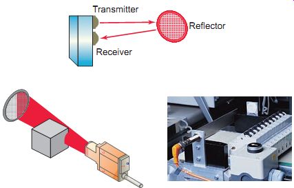
Ill. 35 Retroreflective scan sensor. Reflector; Transmitter; Receiver
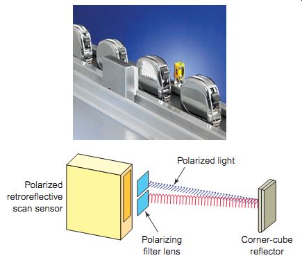
Ill. 36 Polarized retroreflective scan sensor. Polarized retroreflective
scan sensor; Polarizing filter lens; Polarized light Corner-cube reflector
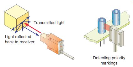
Ill. 37 Diffuse scan sensor. Detecting polarity markings; Transmitted
light; Light reflected; back to receiver
FIBER OPTICS
Fiber optics isn't a scan technique, but another method for transmitting light. Fiber optic sensors use a flexible cable containing tiny fibers that channel light from emitter to receiver. Fiber optics can be used with through beam, retroreflective scan, or diffuse scan sensors, as illustrated in Ill. 38. In through-beam scan, light is emitted and received with individual cables. In retroreflective and diffuse scan, light is emitted and received with the same cable.
Fiber optic sensors systems are completely immune to all forms of electrical interference. The fact that an optical fiber does not contain any moving parts and carries only light means that there is no possibility of a spark. I.e., it can be safely used even in the most hazardous sensing environments such as a refinery for producing gases, grain bins, mining, pharmaceutical manufacturing, and chemical processing. Another advantage of using optical fibers is the luxury it affords users to route them through extremely tight areas to the sensing location. Certain fiber optics materials, particularly the glass fibers, have very high operating temperatures (450°F and higher).
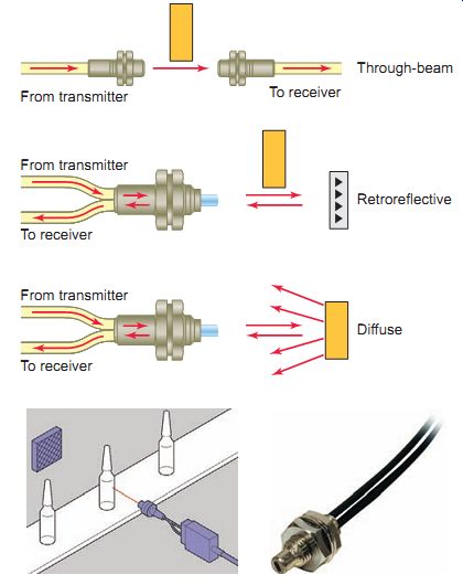
Ill. 38 Fiber optic sensors. Through-beam; To receiver; From transmitter;
Retroreflective; Diffuse
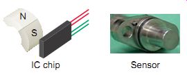
Ill. 39 Hall effect sensor. IC chip Sensor
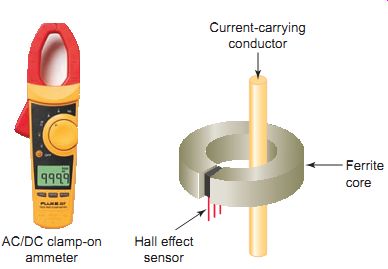
Ill. 40 Hall effect sensor for current measurement. Ferrite core Hall
effect sensor AC/DC clamp-on ammeter Current-carrying conductor
Hall Effect Sensors
Hall effect sensors are used to detect the proximity and strength of a magnetic field. When a current-carrying conductor is placed into a magnetic field, a voltage will be generated perpendicular to both the current and the field.
This principle is known as the Hall effect. A Hall effect sensor switch is constructed from a small integrated circuit (IC) chip like that shown in Ill. 39. A permanent magnet or electromagnet is used to trigger the sensor on and off. The sensor is off with no magnetic field and triggered on in the presence of a magnetic field. Hall effect sensors are designed in a variety of body styles. Selection of a sensor based on body style will vary by application.
Analog-type Hall Effect sensors put out a continuous signal proportional to the sensed magnetic field. An analog linear Hall effect sensor may be used in conjunction with a split ferrite core for current measurement, as illustrated in Ill. 40. The magnetic field across the gap in the ferrite core is proportional to the current through the wire, and therefore the voltage reported by the Hall effect sensor will be proportional to the current. Clamp on ammeters that can measure both AC and DC current use a Hall effect sensor to detect the DC magnetic field induced into the clamp. The signal from the Hall effect device is then amplified and displayed.
Digital-type Hall effect devices are used in magnetically operated proximity sensors. In industrial applications they may serve to determine shaft or gear speed or direction by detecting fluctuations in the magnetic field.
One such application, which involves the monitoring of speed of a motor, is illustrated in Ill. 41. The operation of the device can be summarized as follows:
• When the sensor is aligned with the rotating ferrous gear tooth, the magnetic field will be at its maxi mum strength.
• When the sensor is aligned with the gap between the teeth, the strength of the magnetic field is weakened.
• Each time the tooth of the target passes the sensor, the digital Hall switch activates, and a digital pulse is generated.
• By measuring the frequency of the pulses, the shaft speed can be determined.
• The Hall effect sensor is sensitive to the magnitude of flux, not its rate of change, and as a result the digital output pulse produced is of constant amplitude regardless of speed variations.
• This feature of Hall effect technology allows one to make speed sensors that can detect targets moving at arbitrarily slow speeds, or even the presence or absence of nonmoving targets.
Ultrasonic Sensors
An ultrasonic sensor operates by sending high-frequency sound waves toward the target and measuring the time it takes for the pulses to bounce back. The time taken for this echo to return to the sensor is directly proportional to the distance or height of the object because sound has a constant velocity.
Ill. 42 illustrates a practical application in which the returning echo signal is electronically converted to a 4- to 20-mA output, which supplies a monitored flow rate to external control devices. The 4-20 mA represents the sensor's measurement span. The 4-mA set point is typically placed near the bottom of the empty tank, or the greatest measurement distance from the sensor. The 20-mA set point is typically placed near the top of the full tank, or the shortest measurement distance from the sensor. The sensor will proportionately generate a 4-mA signal when the tank is empty and a 20-mA signal when the tank is full. Ultrasonic sensors can detect solids, fluids, granular objects, and textiles. In addition, they enable the detection of different objects irrespective of color and transparency and therefore are ideal for monitoring transparent objects.
Temperature Sensors
There are many types of temperature sensors that will use various technologies and have different configurations.
The four basic types of temperature sensors commonly used today are thermocouple, resistance temperature detector, thermistor, and IC sensor.
Ill. 41 Monitoring speed using a Hall effect sensor. Digital output Hall effect speed sensor Geartooth sensing unit
Ill. 42 Ultrasonic sensor. Detecting transparent bottles Detecting the level of chocolate; 4- to 20-mA output; Level detection
THERMOCOUPLE
A thermocouple (TC) is a sensor that measures temperature. The thermocouple is by far the most widely used temperature sensor for industrial control. Thermocouples operate on the principle that when two dissimilar metals are joined, a predictable DC voltage will be generated that relates to the difference in temperature between the hot junction and the cold junction ( Ill. 43). The hot junction (measuring junction) is the joined end of a thermocouple that's exposed to the process where the temperature measurement is desired. The cold junction (reference junction) is the end of a thermocouple that's kept at a constant temperature to provide a reference point. E.g., a K-type thermocouple, when heated to a temperature of 300°C at the hot junction, will pro duce 12.2 mV at the cold junction.
The signal produced by a thermocouple is a function of the difference in temperature between the probe tip (hot junction) and the other end of the thermocouple wire (cold junction). For this reason it’s important that the cold (or reference) junction be maintained at a constant known temperature to produce accurate temperature measurements. In most applications the cold junction is maintained at a known (reference) temperature, while the other end is attached to a probe.
A thermocouple probe consists of thermocouple wire housed inside a metallic tube. The wall of the tube is referred to as the sheath of the probe. The tip of the thermo couple probe is available in three different styles: grounded, ungrounded, and exposed, as illustrated in Ill. 44.
The types of metals used in a thermocouple are based on intended operating conditions, such as temperature range and working atmosphere. Different thermocouple types have very different voltage output curves. When a replacement thermocouple is required it’s important that the thermocouple type used in the replacement matches the original. It’s also required that thermocouple or thermocouple extension wire of the proper type be used all the way from the sensing element to the measuring element.
Large errors can develop if this practice isn't followed.
Ill. 43 Thermocouple heat sensor. Chromel (nickel-chromium); 12.2 mV 300 _C; Alumel (nickel-aluminum); type K thermocouple; Cold junction; Hot junction; HEAT Leads
Ill. 44 Thermocouple tip styles.
Grounded Ungrounded Exposed
Ill. 45 Resistance temperature detector. Ceramic support Sheath RTD element; Encapsulated-type RTD wound with platinum wire; Temperature control system; Cool; Heat; 35 _C CONTROLLER RTD; Cooling line; Heating line
RESISTANCE TEMPERATURE DETECTORS
Resistance temperature detectors (RTDs) are wire-wound temperature-sensing devices that operate on the principle of the positive temperature coefficient (PTC) of metals.
That means the electrical resistance of metals is directly proportional to temperature. The hotter they become, the larger or higher the value of their electrical resistance.
This proportional variation is precise and repeatable, and therefore allows the consistent measurement of temperature through electrical resistance detection. Platinum is the material most often used in RTDs because of its superiority regarding temperature limit, linearity, and stability. RTDs are among the most precise temperature sensors available and are normally found encapsulated in probes for external temperature sensing and measurement or enclosed inside devices where they measure temperature as a part of the device's function. Ill. 45 illustrates how an RTD is used as part of a temperature control system. A controller uses the signal from the RTD sensor to monitor the temperature of the liquid in the tank and thereby control heating and cooling lines.
THERMISTORS
Thermistors are generally described as thermally sensitive resistors that exhibit changes in resistance with changes in temperature. This change of resistance with temperature can result in a negative temperature coefficient (NTC) of resistance, where the resistance decreases with an increase in temperature (NTC thermistor). When the resistance increases with an increase in temperature, the result is a positive temperature coefficient (PTC) thermistor. Thermistors tend to be more accurate than RTDs and thermocouples, but they have a much more limited temperature range. Their sensing area is small, and their low mass allows a fairly fast response time of measurement. Ill. 46 shows the circuit symbols used to represent thermistors, along with common configurations. A thermistor placed inside a motor housing is used to supplement the standard overload protection by monitoring the motor winding temperature.
INTEGRATED CIRCUIT
Integrated circuit (IC) temperature sensors use a silicon chip for the sensing element. Most are quite small and their principle of operation is based on the fact that semiconductor diodes have temperature-sensitive voltage versus current characteristics. Although limited in temperature range (below 200°C), IC temperature sensors produce a very linear output over their operating range. There are two main types of IC temperature sensors: analog and digital. Analog sensors can pro duce a voltage or current proportional to temperature.
Digital temperature sensors are similar to analog temperature sensors, but instead of outputting the data in current or voltage, they convert the data into a digital format of 1s and 0s. Digital-output temperature sensors are therefore particularly useful when interfacing to a microcontroller.
Velocity and Position Sensors
TACHOMETER
Tachometer generators provide a convenient means of converting rotational speed into an analog voltage signal that can be used for motor speed indication and control applications. A tachometer generator is a small AC or DC generator that develops an output voltage (proportional to its rpm) whose phase or polarity depends on the rotor's direction of rotation. The DC tachometer generator usually has permanent magnetic field excitation. The AC tachometer generator field is excited by a constant AC supply. In either case, the rotor of the tachometer is mechanically connected, directly or indirectly, to the load. Ill. 48 illustrates motor speed control applications in which a tachometer generator is used to provide a feedback voltage to the motor controller that's proportional to motor speed. The control motor and tachometer generator may be contained in the same or separate housings.
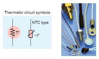
Ill. 46 Thermistors. Thermistor circuit symbols; NTC type
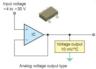
Ill. 47 Integrated circuit temperature sensor. Analog voltage output
type; IC; Voltage output; 10 mV/_C; Input voltage; _4 to _30 V
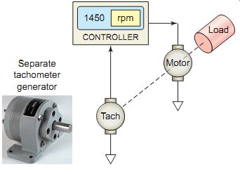
Ill. 48 Tachometer generator. Load; Tach; Motor; 1450 rpm; CONTROLLER;
Separate tachometer generator

Ill. 49 Magnetic pickup sensor. Flux _ density; Time Connector One-piece
shell Coil Pole piece Encapsulant Magnet
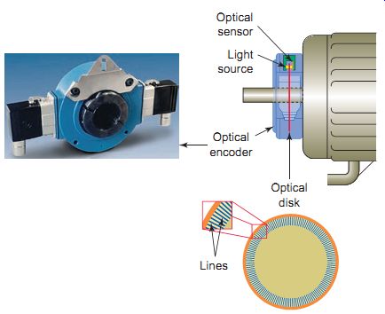
Ill. 50 Optical encoder. Optical encoder Optical sensor Light source
Optical disk Lines
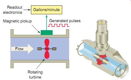
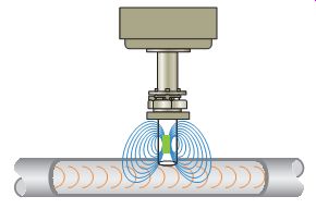
Ill. 51 Turbine flowmeter. Gallons/minute Generated pulses Readout electronics
Magnetic pickup Flow Rotating turbine
MAGNETIC PICKUP
A magnetic pickup is essentially a coil wound around a permanently magnetized probe. When a ferromagnetic object, such as gear teeth, is passed through the probe's magnetic field, the flux density is modulated. This induces AC voltages in the coil. One complete cycle of voltage is generated for each object passed. By measuring the frequency of this signal voltage, the shaft speed can be determined. Ill. 49 shows a magnetic pickup used in conjunction with a 60-tooth gear to measure the rpm of a rotating shaft.
ENCODER
An encoder is used to convert linear or rotary motion into a binary digital signal. Encoders are used in applications such as robotic control where positions have to be precisely determined. The optical encoder illustrated in Ill. 50 uses a light source shining on an optical disk with lines or slots that interrupt the beam of light to an optical sensor. An electronic circuit counts the interruptions of the beam and generates the encoder's digital output pulses.
Flow Measurement
Many processes depend on accurate measurement of fluid flow. Although there are a variety of ways to measure fluid flow, the usual approach is to convert the kinetic energy that the fluid has into some other measurable form. This can be as simple as connecting a paddle to a potentiometer or as complex as connecting rotating vanes to a pulse sensing system or tachometer.
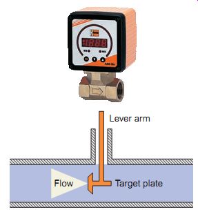
Ill. 52 Target type flowmeter. Kobold Instruments, www.kobold.com. Lever
arm; Target plate Flow
Ill. 53 Magnetic flowmeter.
TURBINE FLOWMETERS
Turbine -type flowmeters are a popular means of measurement and control of liquid products in industrial, chemical, and petroleum operations. Turbine flowmeters, like windmills, utilize their angular velocity (rotation speed) to indicate the flow velocity. The operation of a turbine flowmeter is illustrated in Ill. 51. Its basic construction consists of a bladed turbine rotor installed in a flow tube. The bladed rotor rotates on its axis in proportion to the rate of the liquid flow through the tube. A magnetic pickup sensor is positioned as close to the rotor as practical. Fluid passing through the flow tube causes the rotor to rotate, which generates pulses in the pickup coil. The frequency of the pulses is then transmitted to readout electronics and displayed as gallons per minute.
TARGET FLOWMETERS
Target -type flowmeters insert a target, usually a flat disk with an extension rod, oriented perpendicularly to the direction of the flow. They then measure the drag force on the inserted target and convert it to the flow velocity. One advantage of the target flowmeter over other types is its ability to measure fluids that are corrosive or extremely dirty. Ill. 52 shows a typical target flowmeter. Fluid flow causes the target plate and lever arm to deflect against a spring. A permanent magnet attached to the lever arm and a Hall effect sensor mounted inside the display unit translate the angular motion of the target to an electrical signal that operates a flow rate display.
Magnetic Flowmeters
Magnetic flowmeters, also known as electromagnetic flowmeters or induction flowmeters, obtain the flow velocity by measuring the changes of induced volt age of the conductive fluid passing across a controlled magnetic field. Ill. 53 shows a magnetic flowmeter that can be used with electrically conducting flu ids and offers no restriction to flow. A coil in the unit sets up a magnetic field. If a conductive liquid flows through this magnetic field, a voltage is induced that's proportional to the average flow velocity-the faster the flow rate the higher the voltage. This voltage is picked up by sensing electrodes and used to calculate the flow rate.
QUIZ
- 1. In general, how do sensor pilot devices operate?
- 2. What is the main feature of a proximity sensor?
- 3. List the main components of an inductive proximity sensor.
- 4. Explain the term hysteresis as it applies to a proximity sensor.
- 5. How is a two-wire sensor connected relative to the load it controls?
- 6. In what way is the sensing field of a capacitive proximity sensor different from that of the inductive proximity sensor?
- 7. For what type of target would a capacitive proximity sensor be selected over an inductive type?
- 8. Outline the principle of operation of a photoelectric sensor.
- 9. Name the three most common scan techniques for photoelectric sensors.
- 10. What are the advantages of fiber optic sensing systems?
- 11. Outline the principle of operation of a Hall effect sensor.
- 12. Outline the principle of operation of an ultrasonic sensor.
- 13. List the four basic types of temperature sensors and describe the principle of operation of each.
- 14. Compare the way in which a tachometer and magnetic pickup are used in speed measurement.
- 15. Outline the principle of operation of an optical encoder.
- 16. What approach is usually taken to measurement of fluid flow?
- 17. List three common types of flowmeters.
Actuators
Relays
An actuator, in the electrical sense, is any device that converts an electrical signal into mechanical movement. An electromechanical relay is a type of actuator that mechanically switches electric circuits. Relays play an important role in many motor control systems. In addition to providing control logic by switching multiple control circuits, they are also used for controlling low-current pilot loads such as contactor and starter coils, pilot lights, and audible alarms.
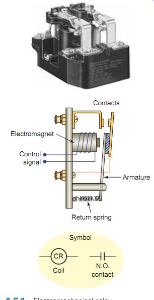
Ill. 54 Electromechanical relay. Symbol Coil N.O. contact CR Return
spring Control signal Electromagnet Contacts Armature
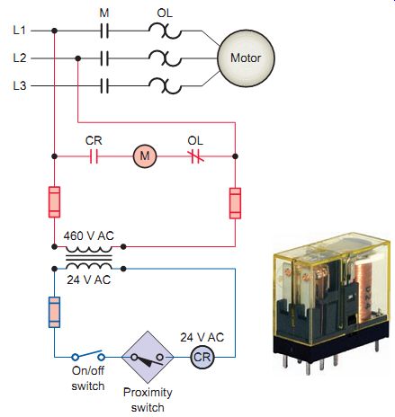
Ill. 55 Relay motor control circuit. 24 V AC On/off switch Proximity
switch CR
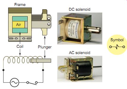
Ill. 56 Solenoid construction and operation. Air Frame Coil Plunger
Symbol DC solenoid AC solenoid
Ill. 57 Linear and rotary solenoid applications. Linear solenoid; Rotary
solenoid
Ill. 54 shows a typical electromechanical control relay. This relay consists of a coil, wound on an iron core, to form an electromagnet. When the coil is energized by a control signal, the core becomes magnetized and sets up a magnetic field that attracts the iron arm of the armature to it. As a result, the contacts on the armature close.
When the current to the coil is switched off, the armature is spring-returned to its normal deenergized position and the contacts on the armature open.
Ill. 55 illustrates one simple application of a control relay used in a motor control circuit. The relay enables the energy in the motor high-power line circuit to be switched by a low-power two-wire proximity switch.
In this example, the proximity switch operates a relay coil whose contacts operate motor starter coil M. The operation of the control circuit can be summarized as follows:
• With the switch on, anytime the proximity switch contacts close, relay coil CR will become energized.
• This in turn will cause the normally open CR contacts to close and complete the path of current to the ‘M’ motor starter. The M motor starter energizes and closes the M contacts in the power circuit, starting the motor.
• When the proximity switch opens, the CR coil de-energizes, opening CR contacts which in turn de-energizes coil M and opens the M contacts in the power circuit to stop the motor.
Solenoids
An electromechanical solenoid is a device that uses electrical energy to magnetically cause mechanical control action. A solenoid consists of a coil, frame, and plunger (or armature, as it’s sometimes called). Ill. 56 shows the basic construction and operation of a solenoid. The coil and frame form the fixed part. When the coil is energized, it produces a magnetic field that attracts the plunger, pulling it into the frame and thus creating mechanical motion.
When the coil is deenergized the plunger returns to its normal position through gravity or assistance from spring assemblies within the solenoid. The frame and plunger of an AC-operated solenoid are constructed with laminated pieces instead of a solid piece of iron to limit eddy cur rents induced by the magnetic field.
The choice of using DC- or AC-operated solenoid coils is usually predetermined by the type of supply voltage available. Most solenoid applications use DC. Differences between DC and AC operated solenoids include:
• AC solenoids tend to be more powerful in the fully open position than DC. This is due to inrush cur rent, which at maximum stroke can be more than 10 times the closed current.
• The coil current for DC solenoids is limited by coil resistance only. The resistance of an AC solenoid coil is very low, so current flow is primarily limited by the inductive reactance of the coil.
• AC solenoids must close completely so that the inrush current falls to its normal value. If an AC solenoid plunger sticks in the open position, a burn out of the coil is likely. DC solenoids take the same current throughout their stroke and cannot overheat through incomplete closing.
• AC-operated solenoids are usually faster than DC, but with a few milliseconds variation in response time, depending on the point of the cycle when the solenoid is energized. DC solenoids are slower but they repeat their closing times accurately against a given load.
• A good AC solenoid, correctly used, should be quiet when closed, but only because its fundamental tendency to hum has been overcome by correct design and accurate assembly. Dirt on the mating faces or mechanical overload may make it noisy. A DC solenoid is naturally quiet.
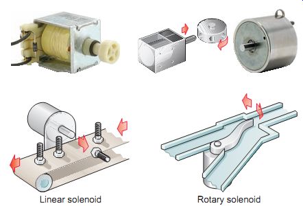
There are two main categories of solenoids: linear and rotary. The direction of movement, either rotary or linear, is based on the mechanical assembly within which the electromagnetic circuit's encased. Rotary solenoids incorporate a mechanical design that converts linear motion to rotary motion. Linear solenoids are usually classified as pull (the electromagnetic path pulls a plunger into the solenoid body) or push (the plunger shaft is pushed out of the frame case).
Ill. 57 illustrates common applications for linear and rotary solenoids.
The linear solenoid application shown is used in part rejection processes
in which electronic inter facing with a sensor produces an actuation signal
to the solenoid. In the rotary solenoid application, the solenoid is used
in a sorting conveyor to control a diverter gate.
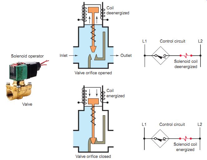
Ill. 58 Solenoid valve. L1 L2 Control circuit Solenoid coil energized
L1 L2 Control circuit Solenoid coil deenergized Valve orifice opened Outlet
Inlet Coil deenergized; Valve orifice closed; Coil energized Valve; Solenoid
operator
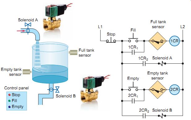
Ill. 59 Solenoid-operated tank filling and emptying operation. ASCO
Valve Inc., www.ascovalve.com. Solenoid B Stop Fill 1CR1 2CR1 2CR2 1CR2
Full tank sensor Empty tank sensor L1 L2 Empty 1CR 2CR Solenoid A Full
tank sensor Empty tank sensor; Control panel; Stop Fill Empty; Solenoid
B; Solenoid A
Solenoid Valves
Solenoid valves are electromechanical devices that work by passing an electrical current through a solenoid, thereby changing the state of the valve. Normally, there is a mechanical element, which is often a spring, that holds the valve in its default position. A solenoid valve is a combination of a solenoid coil operator and valve, which controls the flow of liquids, gases, steam, and other media.
When electrically energized, they either open, shut off, or direct the flow of media.
Ill. 58 illustrates the construction and principle of operation of a typical fluid solenoid valve. The valve body contains an orifice in which a disk or plug is positioned to restrict or allow flow. Flow through the orifice is either restricted or allowed depending on whether the solenoid coil is energized or deenergized. When the coil is energized, the core is drawn into the solenoid coil to open the valve. The spring returns the valve to its original closed position when the current coil is deenergized. A valve must be installed with direction of flow in accordance with the arrow cast on the side of the valve body.
Solenoid valves are commonly used as part of tank filling and emptying processes. Ill. 59 shows the circuit for a tank filling and emptying operation. The operation of the control circuit can be summarized as follows:
• Assuming the liquid level of the tank is at or below the empty level mark, momentarily pressing the FILL push button will energize control relay 1CR.
• Contacts 1CR1 and 1CR2 will both close to seal in the 1CR coil and energize normally closed solenoid valve A to start filling the tank.
• As the tank fills, the normally open empty-level sensor switch closes.
• When the liquid reaches the full level, the normally closed full-level sensor switch opens to open the circuit to the 1CR relay coil and switch solenoid valve A to its deenergized closed state.
• Any time the liquid level of the tank is above the empty level mark, momentarily pressing the EMPTY push button will energize control relay 2CR.
• Contacts 2CR1 and 2CR2 will both close to seal in the 2CR coil and energize normally closed solenoid valve B to start emptying the tank.
• When the liquid reaches the empty level, the normally open empty level sensor switch opens to open the circuit to the 2CR relay coil and switch solenoid valve B to its deenergized closed state.
• The stop button may be pressed at any time to halt the process.
Stepper Motors
Stepper motors operate differently than standard types, which rotate continuously when voltage is applied to their terminals. The shaft of a stepper motor rotates in discrete increments when electrical command pulses are applied to it in the proper sequence. Every revolution is divided into a number of steps, and the motor must be sent a volt age pulse for each step. The amount of rotation is directly proportional to the number of pulses and the speed of rotation is relative to the frequency of those pulses. A 1-degree-per-step motor will require 360 pulses to move through one revolution; the degrees per step is known as the resolution. When stopped, a stepper motor inherently holds its position. Stepper systems are used most often in "open-loop" control systems, where the controller tells the motor only how many steps to move and how fast to move, but does not have any way of knowing what position the motor is at.
The movement created by each pulse is precise and repeatable, which is why stepper motors are so effective for load-positioning applications. Conversion of rotary to linear motion inside a linear actuator is accomplished through a threaded nut and lead screw. Generally, step per motors produce less than 1 hp and are therefore frequently used in low-power position control applications.
Ill. 60 shows a stepper motor/drive unit along with typical rotary and linear applications.
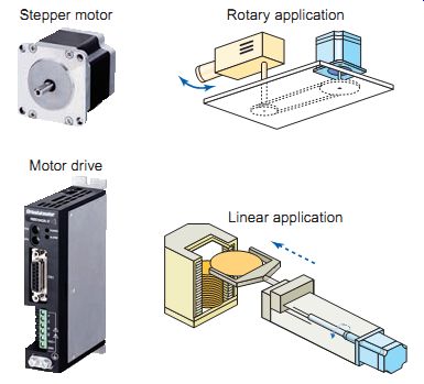
Ill. 60 Stepper motor/drive unit. Rotary application; Linear application;
Stepper motor; Motor drive
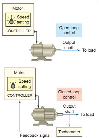
Ill. 61 Open- and closed-loop motor control systems. Output shaft To
load Open-loop control Motor CONTROLLER Speed setting Motor CONTROLLER
Output shaft To load Closed-loop control
Tachometer Feedback signal Speed setting
Servo Motors
All servo motors operate in closed-loop mode, whereas most stepper motors operate in open-loop mode. Closed-loop and open-loop control schemes are illustrated in Ill. 61.
Open loop is control without feedback, e.g., when the controller tells the stepper motor how many steps to move and how fast to move, but does not verify where the motor is. Closed-loop control compares speed or position feedback with the commanded speed or position and generates a modified command to make the error smaller. The error is the difference between the required speed or position and the actual speed or position.
Ill. 62 shows a typical closed-loop servo motor system. The motor controller directs operation of the servo motor by sending speed or position command signals to the amplifier, which drives the servo motor. A feedback device such as an encoder for position and a tachometer for speed are either incorporated within the servo motor or are remotely mounted, often on the load itself. These provide the servo motor's position and speed feedback information that the controller compares to its programmed motion pro file and uses to alter its position or speed.
While stepper motors are DC operated, a servo motor can be either DC or AC operated. Three basic types of servo motors are used in modern servo systems: AC servo motors, based on induction motor designs; DC servo motors, based on DC motor designs; and DC or AC brush less servo motors.
A DC brushless servo motor is shown in Ill. 63.
As the name implies, brushless DC motors (BLDCs) have no brush or commutation mechanism; instead, they are electronically commutated. The stator is normally a three phase stator (A-B-C) like that of an induction motor and the rotor has surface-mounted permanent magnets. Three Hall sensors (H1-H2-H3) are used to detect the rotor position, and commutation is performed electronically, based on signals from the Hall sensor inputs. The signals from the Hall effect sensors are decoded by the controller and used to control the driver circuit, which energizes the stator coils in the proper rotational sequence. Therefore, the motor requires electronic drive in order to operate.
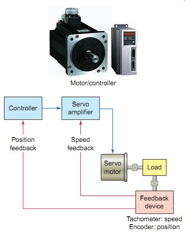
Ill. 62 Closed-loop servo system.
Motor/controller Controller Servo amplifier Feedback device Tachometer: speed Encoder: position Load Position feedback Speed feedback Servo motor
Ill. 63 Brushless DC motor with integrated drive. Motor stator and sensor connections: Reference Run/Stop FWD/REV H1 H2 H3 Hall sensor input Motor control circuit Phase A Phase C Phase B Permanent magnet rotor Y-connected stator Brushless DC motor with integrated electronic drive BLDC motor
QUIZ
1. Define the term actuator as it applies to an electric circuit.
2. In what ways are electromagnetic relays employed in motor control systems?
3. What are the two main parts of an electromagnetic relay?
4. Describe how an electric solenoid operates.
5. Which type of solenoid (AC or DC) is constructed with laminated instead of solid pieces of steel? Why?
6. Why are AC solenoid coils likely to overheat if the plunger sticks in the open position when energized?
7. In what way is the design of a rotary solenoid different from that of a linear solenoid?
8. A solenoid valve is a combination of what two elements?
9. Explain how rotation is achieved in a stepper motor.
10. What is the basic difference between an open-loop and closed-loop positioning or motor speed control system?
11. What do all servo motors have in common?
12. What replaces brushes in a brushless DC motor?
REPAIR/PROBLEM-SOLVING/TROUBLESHOOTING SCENARIOS
1. A defective switch rated for 10 A DC at a given voltage is replaced with one rated for 10 A AC at the same voltage. What is most likely to happen? Why?
2. The resistance of a suspected AC solenoid coil, rated for 2 A at 120 V, is measured with an ohmmeter and found to have a resistance of 1 ohm. Does this mean the coil is shorted? Why?
3. The N.O. and N.C. contacts of a relay with a coil operating voltage of 12 V DC are to be bench checked for faults by using an ohmmeter. Develop a complete outline, including circuit schematics, of the procedure you would follow.
4. A 12-V pilot light is incorrectly replaced with one rated for 120 V. What would be the result?
5. What voltage values are typically produced by thermocouples?
6. A through-beam photoelectric sensor appears to be missing detection of small bottles on a high speed conveyor line. What could be creating this problem?
DISCUSSION TOPICS and CRITICAL THINKING
1. List typical electrical and mechanical problems that may cause failed operation of a mechanically operated limit switch.
2. How might a flow switch be used in a building fire protection system?
3. Should a resistance check of a good thermocouple yield a "low resistance" or "infinite" reading? Why?
4. What does the range adjustment on a float switch accomplish?
5. A stepper motor cannot be bench-checked directly from a power source. Why?