AMAZON multi-meters discounts AMAZON oscilloscope discounts
Cont. from part c
Programmable Logic Controllers (PLCs)
PLC Sections and Configurations
A programmable logic controller (PLC) is an industrial grade computer that is capable of being programmed to perform control functions. The programmable controller has eliminated much of the hard wiring associated with conventional relay control circuits. Other benefits PLCs provide include easy programming and installation, fast control response, network compatibility, troubleshooting and testing convenience, and high reliability. Programmable logic controllers are now the most widely used industrial process control technology.
ill.44 shows the major sections of a programmable logic controller system. Their basic functions are summarized as follows:
Power supply The power supply of a PLC system converts either AC line voltage or, in some applications, a DC source voltage, into low-voltage DC required by the processor and I/O modules. In addition to voltages required for the internal operation of these components, the power supply in certain applications may provide low-voltage DC to external loads as well.
Power supplies are available for different input volt ages including 120 V AC, 240 V AC, 24 V AC, and 24 V DC. The required output current rating of the power supply load on the power supply is based on the type of processor, the number and types of input/output (I/O) modules, and any external loads that may be required to be connected to the power supply.
Processing unit The central processing unit (CPU), also called processor, and associated memory form the intelligence of a PLC system. Unlike other modules that simply direct input and output signals, the CPU evaluates the status of inputs, outputs, and other data as it executes a stored program. The CPU then sends signals to update the status of outputs. Processors are rated as to their available memory and I/O capacity, as well as the different types and number of available programming instructions.
Input module Input and output modules enable the PLC to sense and control the system it’s operating. The prime function of an input module is to take the input signals from the field devices switches or sensors and convert them to logic signals that can be used by the CPU. In addition, the input module provides electrical isolation between the input field devices and the PLC. The types of input modules required depend on the types of input devices used.
Some input modules respond to digital inputs, also called discrete inputs, which are either on or off.
Other input modules respond to analog signals that represent conditions as a range of voltage or current.
Output module Output modules control the system by operating motor starters, contactors, solenoids, and the like. They convert control signals from the CPU into digital or analog values that can be used to control various output field devices (loads). They also provide electrical isolation between the input field devices and the PLC.
Programming device The programming device is used to enter or change the PLC's program or to monitor or change stored values. Once entered, the pro gram is stored in the CPU. A personal computer (PC) is the most commonly used programming device and communicates with CPU via a communications port.
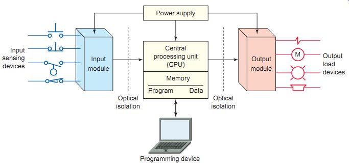
ill.44 The major sections of a PLC system. Output load devices Input
sensing devices Optical isolation Optical isolation Programming device
M Central processing unit (CPU) Memory Program Power supply Data Input
module Output module;
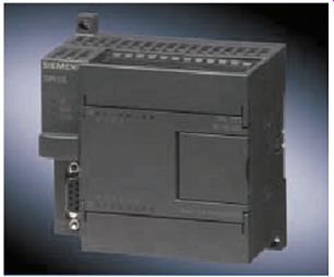
ill.45 Fixed programmable controller. Siemens, www.siemens.com.
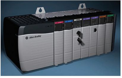
ill.46 Modular programmable controller. Rockwell Automation, www.rockwellautomation.com.
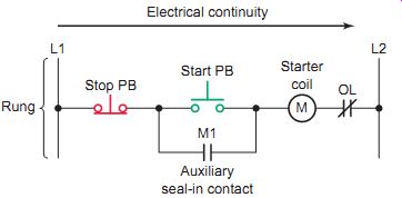
ill. 47 Hard-wired start/stop circuit. Electrical continuity L1 L2;
OL Stop PB; Rung; Start PB Starter coil; M1 Auxiliary seal-in contact;
M
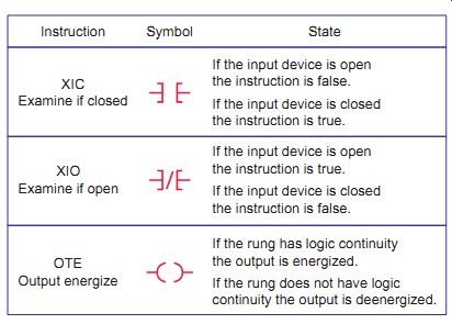
ill.48 Basic PLC instructions.
Symbol State Instruction XIC Examine if closed XIO Examine if open OTE Output energize If the rung has logic continuity the output is energized.
If the rung does not have logic continuity the output is deenergized.
If the input device is closed the instruction is false.
If the input device is open the instruction is true.
If the input device is open the instruction is false.
If the input device is closed the instruction is true.
Small-size fixed PLCs, such as the Micro PLC shown in ill.45, are stand-alone, self-contained units.
A fixed controller consists of a power supply, processor (CPU), and fixed number of input/outputs (I/Os) in a single unit. They are constructed in one package with no separate, removable units. The number of available I/O points varies and usually can be increased by the addition of expansion modules. Fixed controllers are small and less expensive but limited to smaller, less complex applications.
A modular PLC, such as the one shown in ill. 46, is made up of several different physical components. It consists of a rack or chassis, power supply, processor (CPU), and I/O modules. The chassis is divided by compartments into which the separate modules can be plugged.
The complete assembly provides all of the control functions required for a particular application. This feature greatly increases your options and the system's flexibility.
You can choose from a variety of modules available from the manufacturer and mix them any way you desire.
Ladder Logic Programming
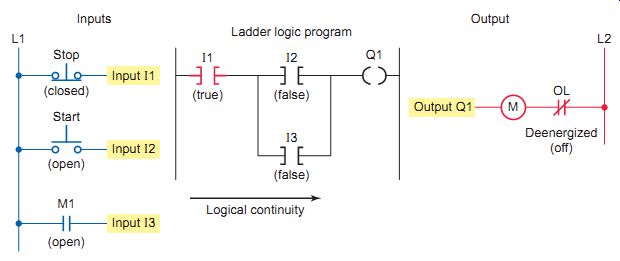
ill.49 Programmed start/stop circuit. Ladder logic program; Inputs Output;
Logical continuity; Deenergized (off)
A program is a user-developed series of instructions that directs the PLC to execute actions. A programming language provides rules for combining the instructions so that they produce the desired actions. Relay ladder logic (RLL) is the standard programming language used with PLCs. Its origin is based on electromechanical relay control. The ladder logic program graphically represents rungs of contacts, coils, and special instruction blocks.
ill.47 shows the traditional electrical diagram for a hard-wired motor start/stop circuit. The diagram consists of two vertical supply lines with a single rung. Every rung contains at least one load device that is controlled, as well the conditions that control the device. The rung is said to have electrical continuity whenever a current path is established between L1 and L2. Pressing the start push button results in electrical continuity to energize the starter coil (M) and close the seal-in contact (M1). After the start but ton is released, electrical continuity is maintained by the seal-in contact. When the stop push button is pressed, electrical continuity is lost and the starter coil deenergizes.
On an electrical diagram, the symbols represent real world devices. In the electrical diagram, the electrical states of the devices are described as being open/closed or off/on. In the ladder logic program, instructions are either false/true or binary 0/1. The three basic PLC instructions ( ill.48) are:
- XIC -Examine if closed instruction
- XIO -Examine if open instruction
- OTE -Output energize instruction
Each of the input and output connection points on a PLC has an "address" associated with it. This address will indicate what PLC input is connected to what input device and what PLC output will drive what output device. Types of addressing formats include rack/slot-based and tag based formats. Addressing formats may vary between PLC modules manufactured by the same company. Also no two different PLC manufacturers have identical addressing formats. Understanding the addressing scheme used is of prime importance when it comes to programming and wiring. PLCs with fixed I/O typically have all their input and output locations predefined.
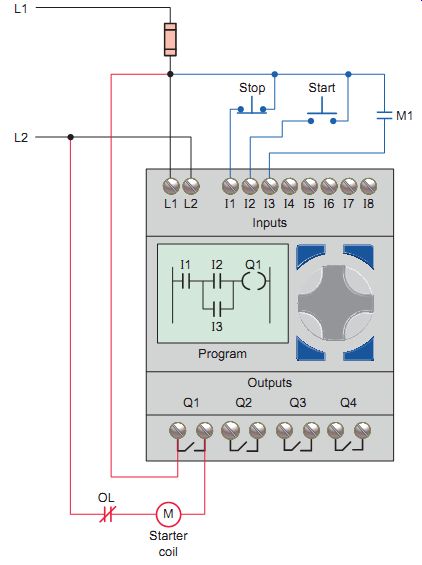
ill.50 PLC wiring designed to implement the motor start/stop control.
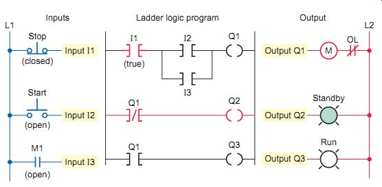
ill.51 Programmed start/stop circuit with remote standby and run pilot
lights.
ill.49 illustrates how the basic PLC instructions are applied in a programmed start/stop motor circuit, which looks and acts much like the electric hard-wired circuit. The operation of the program can be summarized as follows:
• The normally closed stop push button is closed, making the stop instruction (I1) true.
• Closing the start push button makes the start instruction (I2) true and establishes logical continuity of the rung.
• Rung logic continuity energizes the motor starter coil.
• The starter auxiliary contact M1 closes, making its instruction (I3) true.
• After the start button is released, electrical continuity is maintained by the true I3 instruction.
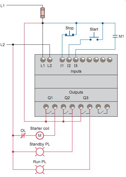
ill.50 illustrates typical PLC wiring, with input/ output notation, designed to implement the motor start/stop control. A fixed controller with eight predefined fixed inputs (I1 to I8) and four predefined fixed relay outputs (Q1 to Q4) is used to control and monitor the motor start/stop operation.
The job is completed as follows:
• The power supply is connected to terminals L1 and L2 of the controller.
• Q1 normally open output relay contact, M starter coil, and the OL relay contact are hard-wired in series with L1 and L2.
• The stop push button, start push button, and M1 auxiliary seal-in contact inputs are connected to I1, I2, and I3 respectively, while the motor starter coil is connected to output Q1.
• The ladder logic program is entered using the front keypad and LCD display or a personal computer connected via the communications port.
• Power is applied and the PLC is placed in the run mode to operate the system.
ill.51 illustrates the original motor start/stop pro gram modified to
include remote standby and run pilot lights.
The operation of the pilot lights is summarized as follows:
• Both examine-if-open and examine-if-closed Q1 programmed contacts are referenced to the starter output coil address Q1.
• When output Q1 is not energized, the examine-if open Q1 instruction will be true, establishing rung continuity and energizing output Q2 to switch on the standby pilot light.
• In addition, when output Q1 is not energized, the examine-if-closed Q1 instruction will be false. No rung continuity exists, so the run pilot light connected to output Q2 will be deenergized.
• When output Q1 is energized the Q1 examine if-open Q1 instruction becomes false and the Q1 examine-if-closed instruction becomes true. This results in the standby pilot light switching off and the run pilot light switching on.
The term hard-wired refers to logic control functions that are determined by the way the devices are interconnected.
Hard-wired logic is fixed; it’s changeable only by altering the way in which the devices are connected. In contrast, programmable control is based on logic functions, which are programmable and easily changed. ill.52 shows the wiring changes that would be required, in addition to the program changes, in order to implement the motor control with standby and run pilot lights. All existing wiring remains intact. The only new wiring required is connection from the remote pilot lights to outputs Q2 and Q3.
Safety considerations need be developed as part of the PLC program. One such consideration involves the use of a motor starter seal-in contact in place of a programmed contact referenced to the output coil instruction. The use of the field-generated starter auxiliary contact status in the program is safer because it provides positive feedback to the processor about the exact status of the motor. Assume, For example, that the OL contact of the starter opens under overload condition. The motor, of course, would stop operating because power would be lost to the starter coil. If the program were implemented using a normally open contact instruction referenced to the output coil instruction as the seal-in for the circuit, the processor would never know that power had been lost to the motor. When the OL was reset, the motor would restart instantly, creating a potentially unsafe operating condition.
ill.52 Wiring changes for remote pilot lights.
ill.53 On-delay timer instruction.
Another safety consideration concerns the wiring of stop buttons. A stop push button is generally considered a safety function as well as an operating function. As such, it should be wired using a normally closed push button and programmed for an examine-if-closed condition. Using a normally open push button programmed for an examine-if-off condition will produce the same logic but is not considered as safe. Assume that the latter configuration is used. If, by some chain of events, the circuit between the push button and the input point were to be broken, the stop button could be depressed forever, but the PLC logic could never react to the stop command because the input would never be true. The same would result if power were lost to the stop pushbutton control circuit. If the normally closed wiring configuration is used, the input point receives power continuously unless the stop function is desired. Any faults occurring with the stop circuit wiring, or a loss of circuit power, would effectively be equivalent to an intentional stop.
Programming Timers
The most commonly used PLC instruction, after coils and contacts, is the timer. Timers are programming functions that keep track of time and provide various responses depending on the elapsed time. They operate in a manner similar to hard-wired electromechanical timers. Even though each manufacturer may represent timer instructions differently on the ladder diagram, most operate in the same manner. Common PLC timer instructions include:
On-delay timer (TON) is a programming instruction typically used to delay the start of a machine or process for a set period of time.
Off-delay timer (TOF) is a programming instruction typically used to delay the shutdown of a machine or process for a set period of time.
Retentive timer (RTO) is a programming instruction typically used to track the length of time a machine has been operating or to shut down a process after an accumulated time period of recurring faults.
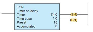
Timers in a programmable controller are output instructions. ill.53 shows the on-delay timer instruction used by Allen-Bradley SLC-500 controllers. The following are associated with this timer instruction:
• Type of timer. TON (on delay).
• Timer number. address T4:0.
• Time base. 1.0 second. The time base of the timer determines the duration of each time base interval.
Time intervals are accumulated or counted by the timer.
• Preset time. 15. Used in conjunction with the time base to set the time-delay period. In this case the time delay period would be 15 seconds (1 second × 15).
• Accumulated value. The time that has elapsed since the timer was last reset.
• (EN)-Enable bit Is true whenever the timer instruction is true.
• (DN)-Done bit. Changes state whenever the accumulated value reaches the preset value.
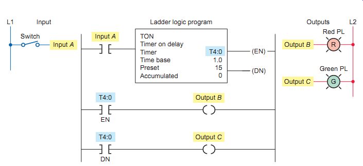
The most commonly used timer is the on-delay type. You can use this timer to turn an output on or off after the timer has been on for a preset period of time. ill.54 illustrates the operation of a typical on-delay programmed timer. The operation of the timer is summarized as follows:
• As long as switch input A is true (closed), the timer on delay T4:0 will increment every 1 second toward the preset value of 15 seconds.
• As long as switch input A is true (closed), the timer's enable bit (EN) will be true or set to 1. With rung continuity established, the green pilot light output C will be energized (turned on) at all times that the switch is closed.
• The current number of seconds that have passed will be displayed in the accumulated value portion of the instruction.
ill.54 On-delay programmed timer.
ill.55 Wiring for the on-delay timer using the Allen-Bradley SLC 500
modular controller. Input LEDs for input terminal status; Output LEDs
for output terminal status; Hinged module cover with terminal identification
• When the accumulated value is equal to the preset value, the timer's done bit (DN) will be true or set to 1. Rung continuity is established and the red pilot light output B will be energized (turned on).
• The processor resets the accumulated time to zero when the rung condition goes false, regardless of whether the timer timed out or not.
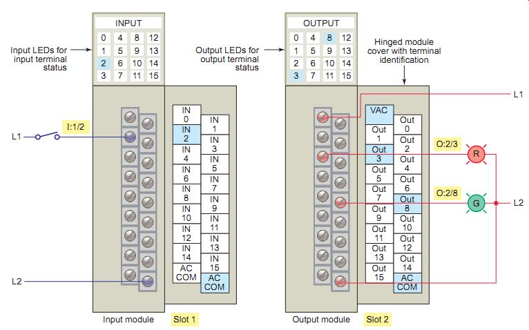
ill.55 shows the wiring for the on-delay timer implemented using the Allen-Bradley SLC 500 modular controller with slot-based addressing. A 16-point (0 to 15)
AC input module is plugged into slot 1 and a 16-point (0 to 15) AC output module into slot 2 of the single-rack chassis. The wiring is as shown and the addressing format is as follows:
Address I:1/2 (switch input A). The letter I indicates that it’s an input, the 1 indicates that the AC input module is in slot 1, and the 2 indicates the terminal of the module to which it’s connected.
Address O:2/3 (red PL output B) The letter O indicates that it’s an output, the 2 indicates that the AC output module is in slot 2, and the 3 indicates the terminal of the module to which it’s connected.
Address O:2/8 (green PL output C) The letter O indicates that it’s an output, the 2 indicates that the AC output module is in slot 2, and the 8 indicates the terminal of the module to which it’s connected.
Programming Counters
Most PLC manufacturers provide counters as part of their instruction set. A programmed counter can count, calculate, or keep a record of the number of times something happens. One of the most common counter applications is counting the number of items moving past a given point.
The two counter types are the count-up (CTU) counter and the count-down (CTD) counter. Count-up instructions are used alone or in conjunction with count-down instructions having the same address.
Counters, like timers, in a programmable controller are output instructions. Other similarities include the following:
• A timer and counter both have an accumulator.
For a timer, the accumulator is the number of time base intervals the instruction has counted.
For a counter, the accumulator is the number of false-to-true transitions of its logic rung that have occurred.
• A timer and counter both have a preset value. The preset value is the set point that you enter in the timer or counter instruction. When the accumulated value becomes equal to or greater than the preset value, the done bit (DN) status is set to 1.
ill.56 shows the standard counter instruction used by Allen-Bradley controllers. The following are associated with this counter instruction:
• Type of counter. Up counter (CTU).
• Counter number. Address C5:1.
• Preset value. 7.
• Accumulated value. Initially set at 0.
• (CU)-enable bit . Is true whenever the rung conditions for the counter are true.
• ( D N ) - d o n e b i t . Changes state whenever the accumulated value reaches the preset value.
• ( O V ) - overf low bit. Is true whenever the counter counts past its maximum value.
• ( R E S ) - R e s e t . Instruction with the same address as the counter that is being reset is used to return counter accumulator values to zero.
Count-up counters are used when a total count is needed. The number stored in the counter accumulator is incremented each time the logic rung for the counter goes from false to true. It thus can be used to count false-to-true transitions of an input instruction and then trigger an event after a preset number of counts or transitions. The up counter output instruction will increment by 1 each time the counted event occurs.
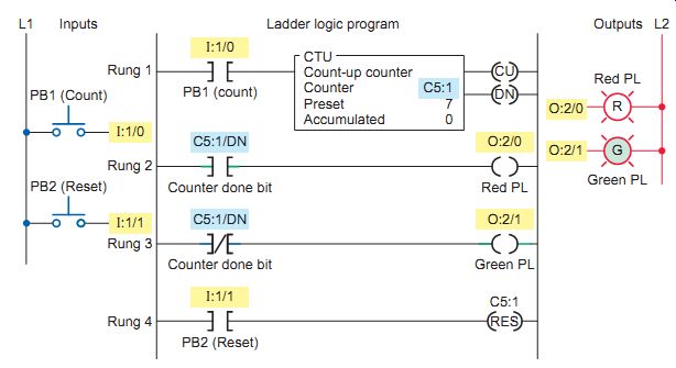
ill.57 illustrates the operation of a programmed up-counter used to turn the red pilot light on and the green pilot light off after an accumulated count of 7. ill.58 shows the wiring for the up-counter implemented using the Allen-Bradley SLC 500 modular controller with slot based addressing. The operation of the program is summarized as follows:
• Operation of PB1 (input I:1/0) provides the off-to-on transition pulses that are counted by the counter.
• The preset value of the counter is set to 7.
• Each false-to-true transition of rung 1 increases the counter's accumulated value by 1.
• After 7 pulses, or counts, when the preset counter value equals the accumulated counter value, output DN is energized.
• As a result, rung 2 becomes true and energizes output 0:2/0 to switch the red pilot light on.
• At the same time, rung 3 becomes false and deenergizes output 0:2/1 to switch the green pilot light off.
• The counter is reset by closing PB2 (input I:1/1) and resets the accumulated count to zero.
• Counting can resume when rung 4 goes false again.
The down-counter output instruction will count down or decrement by 1 each time the counted event occurs. Count down counters (CTDs) are used when a preset number of items (or events) exist and the number must be decreased (or decremented) as items are taken away or events occur.
ill.59 Parking garage counter.
An example of a down-counter application is keeping track of the number of parts leaving a storage bin.
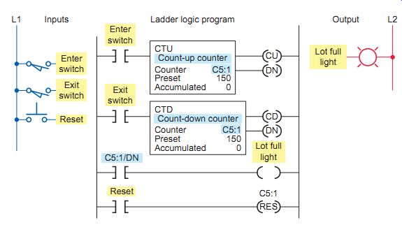
Often the down-counter is used in conjunction with the up-counter to form an up/down-counter. A typical application for an up/down-counter could be to keep count of the cars that enter and leave a parking garage. ill.59 shows a PLC program that could be used to implement this application. The operation of the program is summarized as follows:
• As a car enters, it triggers the up-counter output instruction and increments the accumulated count by 1.
ill.56 Up-counter (CTU) instruction. Count-up counter CTU Counter Preset Accumulated
ill.57 Programmed up-counter.
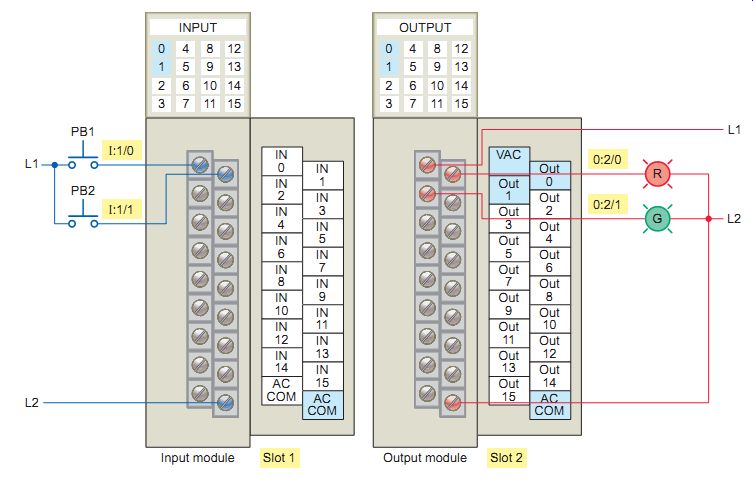
ill.58 Wiring for the up-counter implemented using the Allen-Bradley
SLC 500 controller.
• Conversely, as a car leaves, it triggers the down counter output instruction and decrements the accumulated count by 1.
• Because both the up- and down-counters have the same address, the accumulated value will be the same in both.
• Whenever the accumulated value equals the preset value, the counter output is energized to light up the lot full sign.
• A reset button has been provided to reset the accumulated count.
QUIZ
1. What is a programmable logic controller and how is it utilized in motor applications?
2. List the five major components of a PLC system along with the function provided by each.
3. List the advantages of fixed and modular PLCs.
4. Explain the function of a PLC program.
5. Compare the way in which the states of devices are referred to in an electrical diagram and in a ladder logic program.
6. When does logic continuity occur in a rung of a PLC ladder logic program?
7. Compare hard-wired-type control with programmable control.
8. For safety reasons, a programmed start/stop circuit is always wired using normally closed stop push buttons. Why?
9. Compare the way in which electromechanical and programmed timers operate.
10. State what timer instruction(s) is associated with each of the following:
a. Time that has elapsed since the timer was last reset.
b. Time-delay period.
c. Contact that changes state after the timer times out.
11. What would be the correct address for a push button connected to terminal 4, slot 1, of a single-rack SCL 500 modular PLC controller?
12. List three common functions programmed counters perform.
13. What does the accumulator of a programmed counter count?
14. How is a programmed counter reset to zero?
15. Explain the principle of operation of an up/down counter.
REPAIR/ TROUBLESHOOTING SCENARIOS
1. Most VFD manufacturers provide a special terminal block for DC bus voltage measurement. What conditions could bus voltage measurements be used to check for?
2. For each VFD problem given, list what things in general you would check to determine the problem.
a. Motor does not start-no output voltage to the motor.
b. Drive started but motor not rotating-a speed of 0 Hz is displayed.
c. Motor not accelerating properly.
3. What might be the consequence of setting the acceleration time of a DC drive to a very low value.
4. A normally closed contact-type limit switch is programmed to operate a solenoid valve as part of a motor control system. This limit switch is to be replaced with a normally open contact type. What changes, if any, would be required to have the circuit operate as before.
FURTHER DISCUSSION, OTHER TOPICS and CRITICAL THINKING
1. AC adjustable-speed drives are available with a broad selection of features. Do a vendor search on the Internet and prepare a paper on the standard and optional features of a VFD of your choice or one assigned by the instructor.
2. Why might you want to copy your drive parameter settings if this option is available to you?
3. The use of a bypass contactor circuit to operate a DC drive is not an option. Explain why.
4. Three motors are to be started in sequence with a 10-second time delay between them. Design a PLC program that will perform this operation.
5. A parking garage has one entrance and two exits.
Design a PLC program that will track the number of vehicles parked in the garage at any one time.