AMAZON multi-meters discounts AMAZON oscilloscope discounts
Cont. from part b
DC Motor Drive Fundamentals
Applications
DC drive technology is the oldest form of electrical speed control. The speed of a DC motor is the simplest to control, and it can be varied over a very wide range. These drives are designed to handle applications such as:
Winders/coilers--In motor winder operations, maintaining tension is very important. DC motors are able to operate at rated current over a wide speed range, including low speeds.
Crane/hoist--DC drives offer several advantages in applications that operate at low speeds, such as cranes and hoists. Advantages include low-speed accuracy, short-time overload capacity, size, and torque providing control. ill.31 shows a typical DC hoist motor and drive used on hoisting applications where an overhauling load is present.
Generated power from the DC motor is used for braking and excess power is fed back into the AC line. This power helps reduce energy requirements and eliminates the need for heat-producing dynamic braking resistors. Peak current of at least 250 percent is available for short-term loads.
Mining/drilling--The DC motor drive is often preferred in the high-horsepower applications required in the mining and drilling industry. For this type of application, DC drives offer advantages in size and cost. They are rugged, dependable, and industry proven.
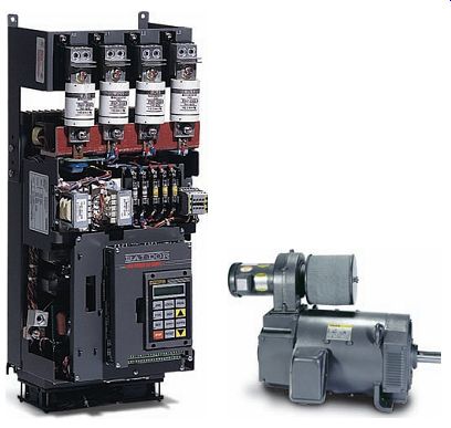
ill.31 Typical DC hoist motor and drive.
DC Drives-Principles of Operation
DC electronic variable-speed drives vary the speed of DC motors with greater efficiency and speed regulation than resistor control circuits. Since the speed of a DC motor is directly proportional to armature voltage and inversely proportional to field current, either armature voltage or field current can be used to control speed. To change the direction of rotation of a DC motor, either the armature polarity can be reversed ( ill.32), or the field polarity can be reversed.
The block diagram of a DC drive system made up of a DC motor and an electronic drive controller is shown in ill.33. The shunt motor is constructed with armature and field windings. A common classification of DC motors is by the type of field excitation winding. Shunt wound DC motors are the most commonly used type for adjustable-speed control. In most instances the shunt field winding is excited, as shown, with a constant-level voltage from the controller. The SCR (silicon controller rectifier), also known as thyristor, of the power conversion section converts the fixed-voltage alternating current (AC) of the power source to an adjustable-voltage, controlled direct current (DC) output which is applied to the armature of a DC motor. Speed control is achieved by regulating the armature voltage to the motor. Motor speed is directly proportional to the voltage applied to the armature.
The main function of a DC drive is to convert the fixed applied AC voltage into a variable rectified DC voltage.
SCR switching semiconductors provide a convenient method of accomplishing this. They provide a controllable power output by phase angle control. The firing angle, or point in time where the SCR is triggered into conduction, is synchronized with the phase rotation of the AC power source, as illustrated in ill.34. The amount of rectified DC voltage is controlled by timing the input pulse current to the gate. Applying gate current near the beginning of the sine-wave cycle results in a higher aver age voltage applied to the motor armature. Gate current applied later in the cycle results in a lower average DC output voltage. The effect is similar to a very high speed switch, capable of being turned on and off at an infinite number of points within each half-cycle. This occurs at a rate of 60 times a second on a 60-Hz line, to deliver a precise amount of power to the motor.
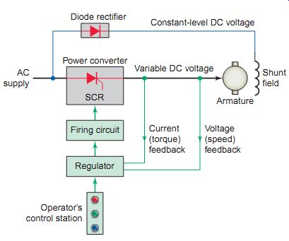
ill.33 Block diagram of a DC drive system. Voltage (speed) feedback;
Regulator; Firing circuit; Current (torque) feedback; Diode rectifier
Constant-level DC voltage; Power converter; Variable DC; voltage AC supply
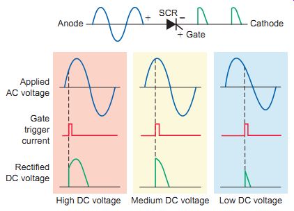
ill.34 SCR conversion from AC to variable DC. High DC voltage Medium
DC voltage Low DC voltage; Applied; AC voltage; Gate trigger current;
Rectified; DC voltage
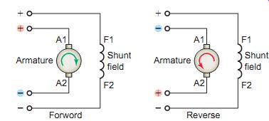
ill.32 Changing direction by reversing the polarity of the armature.
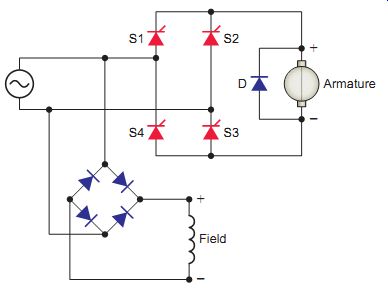
ill.35 Fully controlled SCR bridge rectifier powered by a single-phase
AC supply.
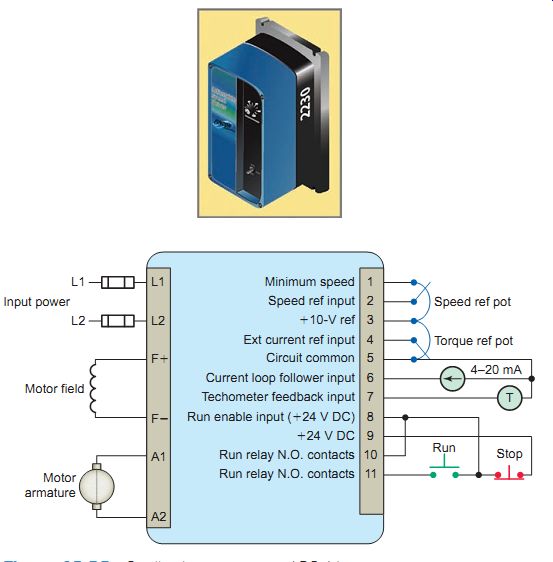
ill.36 Smaller-horsepower-rated DC drive.
Single-Phase Input-DC Drive
Armature voltage-controlled DC drives are constant torque drives, capable of rated motor torque at any speed up to rated motor base speed. Fully controlled rectifier circuits are built with SCRs. ill.35 shows a fully controlled SCR bridge rectifier powered by a single-phase AC supply. The SCRs rectify the supply voltage (changing the voltage from AC to DC) as well as controlling the output DC voltage level. In this circuit, silicon controlled rectifiers S1 and S3 are triggered into conduction on the positive half of the input waveform and S2 and S4 on the negative half. Freewheeling diode D (also called a suppressor diode) is connected across the armature to provide a path for release of energy stored in the armature when the applied voltage drops to zero. A separate diode bridge rectifier is used to convert the alternating current to a constant direct current required for the field circuit.
Single-phase controlled bridge rectifiers are commonly used in the smaller-horsepower DC drives such as the one shown in ill.36. The terminal diagram shows the input and output power and control terminations available for use with the drive. Features include:
- • Speed or torque control
- • Tachometer input
- • Fused input
- • Speed or current monitoring (0-10 V DC or 4-20 mA)
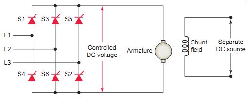
ill.37 Three-phase fully controlled rectifier. Shunt field; Separate
DC source; Controlled DC voltage; Armature
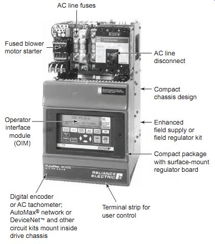
Ill. 38 Three-phase input DC drive. Three-Phase Input-DC Drive [[
Digital encoder or AC tachometer; AutoMax® network or DeviceNet™ and other
circuit kits mount inside drive chassis Compact package with surface-mount
regulator board Enhanced field supply or field regulator kit Fused blower
motor starter Operator interface module (OIM) Compact chassis design AC
line disconnect AC line fuses Terminal strip for user control ill.38 Three-phase
input DC drive.]]
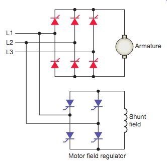
ill.39 DC drive motor field regulator.
Controlled bridge rectifiers are not limited to single-phase designs. In most commercial and industrial control systems, AC power is available in three-phase form for maximum horsepower and efficiency. Typically six SCRs are connected together, as shown in ill.37, to make a three-phase fully controlled rectifier. This three-phase bridge rectifier circuit has three legs, each phase connected to one of the three phase voltages. It can be seen that the bridge circuit has two halves, the positive half consisting of the SCRs S1, S3, and S5 and the negative half consisting of the SCRs S2, S4, and S6. At any time when there is current flow, one SCR from each half conducts.
The variable DC output voltage from the rectifier sup plies voltage to the motor armature in order to run it at the desired speed. The gate firing angle of the SCRs in the bridge rectifier, along with the maximum positive and negative values of the AC sine wave, determine the value of the motor armature voltage. The motor draws current from the three-phase AC power source in proportion to the amount of mechanical load applied to the motor shaft. Unlike AC drives, bypassing the drive to run the motor is not possible.
Larger-horsepower three-phase drive panels often consist of a power module mounted on a chassis with line fuses and disconnect. This design simplifies mounting and makes connecting power cables easier as well. ill.38 shows a three-phase input DC drive with the following drive power specifications:
• Nominal line voltage for three-phase-230/460 V AC
• Voltage variation-+15%, -10% of nominal
• Nominal line frequency-50 or 60 cycles per second
• DC voltage rating 230 V AC line: Armature voltage 240 V DC; field voltage 150 V DC
• DC voltage rating 460 V AC line: Armature voltage 500 V DC; field voltage 300 V DC
Field Voltage Control
To control the speed of a DC motor below its base speed, the voltage applied to the armature of the motor is varied while the field voltage is held at its nominal value. To control the speed above its base speed, the armature is supplied with its rated voltage and the field is weakened. For this reason, an additional variable-voltage field regulator, as illustrated in ill.39, is needed for DC drives with field voltage control. Field weakening is the act of reducing the current applied to a DC motor shunt field. This action weakens the strength of the magnetic field and thereby increases the motor speed. The weakened field reduces the counter emf generated in the armature; therefore the armature current and the speed increase. Field loss detection must be pro vided for all DC drives to protect against excessive motor speed due to loss of motor field current.
DC drives with motor field control provide coordinated automatic armature and field voltage control for extended speed range and constant-horsepower applications. The motor is armature-voltage-controlled for constant-torque, variable-horsepower operation to base speed, where it s transferred to field control for constant-horsepower, variable-torque operation to motor maximum speed.
Nonregenerative and Regenerative DC Drives
Nonregenerative DC drives, also known as single-quadrant drives, rotate in one direction only and they have no inherent braking capabilities. Stopping the motor is done by removing voltage and allowing the motor to coast to a stop. Typically nonregenerative drives operate high friction loads such as mixers, where the load exerts a strong natural brake. In applications where supplemental quick braking and/or motor reversing is required, dynamic braking and forward and reverse circuitry, such as shown in ill.40, may be provided by external means.
Dynamic braking (DB) requires the addition of a DB contactor and DB resistors that dissipate the braking energy as heat. The addition of an electromechanical (magnetic) reversing contactor or manual switch permits the reversing of the controller polarity and therefore the direction of rotation of the motor armature. Field contactor reverse kits can also be installed to provide bidirectional rotation by reversing the polarity of the shunt field.
All DC motors are DC generators as well. The term regenerative describes the ability of the drive under braking conditions to convert the generated energy of the motor into electrical energy, which is returned (or regenerated) to the AC power source. Regenerative DC drives operate in all four quadrants purely electronically, without the use of electromechanical switching contactors:
• Quadrant I-Drive delivers forward torque, motor rotating forward (motoring mode of operation). This is the normal condition, providing power to a load similar to that of a motor starter.
• Quadrant II-Drive delivers reverse torque, motor rotating forward (generating mode of operation). This is a regenerative condition, where the drive itself is absorbing power from a load, such as an overhauling load or deceleration.
• Quadrant III-Drive delivers reverse torque, motor rotating reverse (motoring mode of opera tion). Basically the same as in quadrant I and similar to a reversing starter.
• Quadrant IV-Drive delivers forward torque with motor rotating in reverse (generating mode of operation). This is the other regenerative condition, where again, the drive is absorbing power from the load in order to bring the motor towards zero speed.
A single-quadrant nonregenerative DC drive has one power bridge with six SCRs used to control the applied voltage level to the motor armature. The nonregenerative drive can run in only motoring mode, and would require physically switching armature or field leads to reverse the torque direction. A four-quadrant regenerative DC drive will have two complete sets of power bridges, with 12 con trolled SCRs connected in inverse parallel as illustrated in ill.41. One bridge controls forward torque, and the other controls reverse torque. During operation, only one set of bridges is active at a time. For straight motoring in the forward direction, the forward bridge would be in control of the power to the motor. For straight motoring in the reverse direction, the reverse bridge is in control.
Cranes and hoists use DC regenerative drives to hold back "overhauling loads" such as a raised weight, or a machine's flywheel. Whenever the inertia of the motor load is greater than the motor rotor inertia, the load will be driving the motor and is called an over hauling load. Overhauling load results in generator action within the motor, which will cause the motor to send cur rent into the drive. Regenerative braking is summarized as follows:
• During normal forward operation, the forward bridge acts as a rectifier, supplying power to the motor. During this period gate pulses are withheld from reverse bridge so that it’s inactive.
• When motor speed is reduced, the control circuit withholds the pulses to the forward bridge and simultaneously applies pulses to reverse bridge.
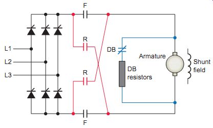
ill.40 Nonregenerative DC drive with external dynamic braking and reversing
contactors.
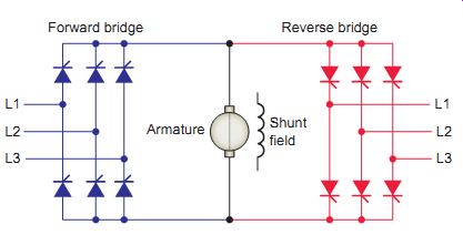
ill.41 Four-quadrant regenerative DC drive. Forward bridge; Reverse
bridge
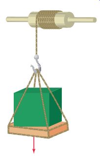
ill.42 Motor overhauling load.
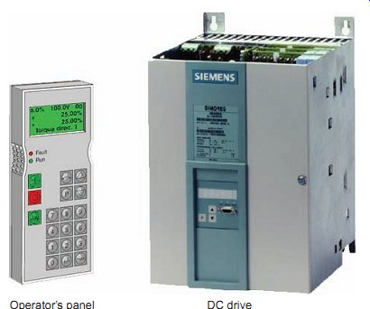
ill.43 Operator's panel used for programming of control setup and operating
parameters for a DC drive.
During this period, the motor acts as a generator, and the reverse bridge conducts current through the armature in the reverse direction back to the AC line. This current reverses the torque, and the motor speed decreases rapidly.
Both regeneration and dynamic braking slow down a rotating DC motor and its load. However, there are significant differences in stopping time and controllability during stopping, and safety issues depending on how one defines what should happen under emergency conditions. Regenerative braking will stop the load smoothly and faster than a dynamic brake for fast stop or emergency stop requirements. In addition regenerative braking will regenerate power to the supply if the load is overhauling.
Parameter Programming
Programming parameters associated with DC drives are extensive and similar to those used in conjunction with AC drives. An operator's panel is used for programming of control setup and operating parameters for a DC drive ( ill.43).
SPEED SETPOINT
This signal is derived from a closely regulated fixed voltage source applied to a potentiometer. The potentiometer has the capability of accepting the fixed voltage and dividing it down to any value, For example, 10 to 0 V, depending on where it’s set. A 10-V input to the drive from the speed potentiometer corresponds to maximum motor speed and 0 V corresponds to zero speed. Similarly any speed between zero and maximum can be obtained by adjusting the speed control to the appropriate setting.
SPEED FEEDBACK INFORMATION
In order to "close the loop" and control motor speed accurately, it’s necessary to provide the control with a feed back signal related to motor speed. The standard method of doing this in a simple control is by monitoring the armature voltage and feeding it back into the drive for comparison with the input setpoint signal. The armature voltage feedback system is generally known as a voltage regulated drive .
A second and more accurate method of obtaining the motor speed feedback information is from a motor mounted tachometer. The output of this tachometer is directly related to the speed of the motor. When tachometer feedback is used, the drive is referred to as a speed regulated drive .
In some newer high-performance digital drives, the feedback can come from a motor-mounted encoder that feeds back voltage pulses at a rate related to motor speed.
These pulses are counted and processed digitally and compared to the setpoint, and an error signal is produced to regulate the armature voltage and speed.
CURRENT FEEDBACK INFORMATION
The second source of feedback information is obtained by monitoring the motor armature current. This is an accurate indication of the torque required by the load.
The current feedback signal is used to eliminate the speed droop that normally would occur with increased torque load on the motor and to limit the current to a value that will protect the power semiconductors from damage. The current-limiting action of most controls is adjustable and is usually called current limit or torque limit.
MINIMUM SPEED
In most cases, when the controller is initially installed the speed potentiometer can be turned down to its lowest point and the output voltage from the controller will go to zero, causing the motor to stop. There are, how ever, situations where this is not desirable. E.g., there are some applications that may need to be kept running at a minimum speed and accelerated up to operating speed as necessary. The typical minimum speed adjustment is from 0 to 30 percent of motor base speed.
MAXIMUM SPEED
The maximum speed adjustment sets the maximum speed attainable. In some cases it's desirable to limit the motor speed (and machine speed) to something less than would be available at this maximum setting. The maximum adjustment allows this to be done.
IR COMPENSATION
Although a typical DC motor presents a mostly inductive load, there is always a small amount of fixed resistance in the armature circuit. IR compensation is a method used to adjust for the drop in a motor's speed due to armature resistance. This helps stabilize the motor's speed from a no-load to full-load condition. IR compensation should be applied only to voltage-regulated drives.
ACCELERATION TIME
As its name implies, the acceleration time adjustment will extend or shorten the amount of time for the motor to go from zero speed up to the set speed. It also regulates the time it takes to change speeds from one setting (e.g., 40 per cent) to another setting (e.g., 80 percent).
DECELERATION TIME
The deceleration time adjustment allows loads to be slowed down over an extended period of time. example.., if power is removed from the motor and it stops in 3 seconds, then the deceleration time adjustment would allow you to adjust this time typically within a 0.5- to 30-second range.
QUIZ:
1. List three types of operations where DC drives are commonly found.
2. How can the speed of a DC motor be varied?
3. What are the two main functions of the SCR semi conductors used in a DC drive power converter?
4. Explain how SCR phase angle control operates to vary the DC output from an SCR.
5. Armature-voltage-controlled DC drives are classified as constant-torque drives. What does this mean?
6. Why is three-phase AC power, rather than single phase, used to power most commercial and industrial DC drives?
7. List what input line and output load voltage information must be specified for a DC drive.
8. How can the speed of a DC motor be increased above that of its base speed?
9. Why must field loss protection be provided for all DC drives?
10. Compare the braking capabilities of nonregenerative and regenerative DC drives.
11. A regenerative DC drive requires two sets of power bridges. Why?
12. Explain what is meant by an overhauling load.
13. What are the advantages of regenerative braking versus dynamic braking?
14. How is the desired speed of a drive normally set?
15. List three methods used by DC drives to send feed back information from the motor back to the drive regulator.
16. What functions require monitoring of the motor armature current?
17. Under what operating condition would the mini mum speed adjustment parameter be utilized?
18. Under what operating condition would the maxi mum speed adjustment parameter be utilized?
19. IR compensation is a parameter found in most DC drives. What is its purpose?
20. What, in addition to the time it takes for the motor to go from zero to set speed, does acceleration time regulate?