AMAZON multi-meters discounts AMAZON oscilloscope discounts
Cont. from part a
VFD Installation and Programming Parameters
Careful planning of your VFD installation will help avoid many problems. Follow the instructions from the VFD manufacturer for required and optional installation requirements. Important considerations include temperature and line power quality requirements, along with electrical connections, grounding, fault protection, motor protection, and environmental parameters.
Selecting the Drive
In selecting a drive, consideration must be given to the load characteristics of the driven machinery. The three basic load categories can be summarized as follows:
• Constant-torque loads require a constant motor torque throughout the operational speed range.
Loads of these types are essentially friction loads such as traction drives and conveyors.
• Variable-torque loads require much lower torque at low speeds than at high speeds. Loads that exhibit variable torque characteristics include centrifugal fans, pumps, and blowers.
• Shock (impact) loads require a motor to operate at normal load conditions followed by a sudden, large load applied to the motor. An example would be the sudden shock load that results from engaging a clutch that applies a large load to the motor (as it would during a hard start). This current spike could cause the VFD to trip as a result an excessive motor current fault.
Line and Load Reactors
A VFD reactor, as shown in ill.13, is basically an inductor installed on the input or output of the drive.
Line reactors stabilize the current waveform on the input side of a VFD, reducing harmonic distortion and the burden on upstream electrical equipment. Harmonics are high-frequency voltage and current distortions within the power system normally caused by nonlinear loads that don’t have a constant current draw, but rather draw current in pulses. VFDs create harmonics when they convert AC to DC and DC back to AC.
By absorbing line spikes and filling some voltage sags, line and load reactors can prevent overvoltage and undervoltage tripping problems. Load reactors, connected between the VFD and motor, will dampen overshoot peak voltage and reduce motor heating and audible noise. A load reactor helps to extend the life of the motor and increase the distance that the motor can be from the drive.
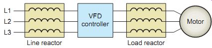
ill.13 VFD reactor.
Location
Location is an important consideration in installing VFDs as this can have a significant effect on the drive's performance and reliability. Location considerations are summarized as follows:
• Mount the drive near the motor. Excessive cable length between the VFD and the motor can result in extremely high voltage spikes at the motor leads. It’s important to verify the maximum cable distance stated in the drive specifications, when you are installing drives onto AC induction motors. Excessive voltages can reduce the expected life of the insulation system, especially non-inverter-duty motors.
• The enclosure surrounding the drive should be well ventilated or in a climate-controlled environment, as the build up of excess heat may damage the VFD components over time. Large fluctuations in ambient temperatures can result in condensation forming inside the drive enclosures and possibly damaging components.
• Locations in dusty, wet, and corrosive environments, constant vibration, and direct sunlight should be avoided.
• The location should have adequate lighting and sufficient working space to carry out maintenance of the drive. NEC Article 110 lists requirements for working space and illumination.
Enclosures
Once a suitable location is chosen, it’s then important to select the appropriate NEMA-type enclosure on the basis of use and service. Factory enclosures of VFDs, such as the one shown in ill.14, should have a NEMA rating appropriate to the level of protection for the environment.
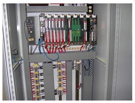
ill.14 VFD mounted within an enclosure.
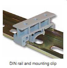
ill.15 VFD mounting technique. E.g., Winford Engineering, LLC., www.winford.com.
DIN rail and mounting clip
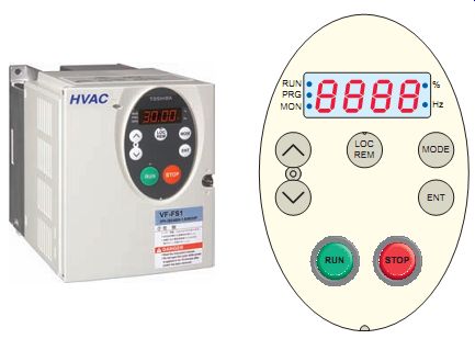
ill.16 Typical VFD operator interface.
Mounting Techniques
Most small VFDs are mounted in rack slots or on a DIN rail as illustrated in ill.15. The clips for mounting to the DIN rail are usually built into the fins of the heat sink to which the VFD is mounted. This makes them easily installable in control cabinets. Larger VFD units usually have through-hole mounting to accommodate individual fasteners. The fastening method should be adequate to support the weight of the drive and allow the free flow of air across the heat sink; airflow in some applications is aided by a cooling fan.
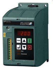
Operator Interface
The typical VFD operator interface, shown in ill.16, provides a means for an operator to start and stop the motor and adjust the operating speed. Additional operator control functions might include reversing and switching between manual speed adjustment and automatic control from an external process control signal. The operator interface often includes an alphanumeric display and/or indication lights and meters to provide information about the operation of the drive. When mounted within another enclosure, a remote operator keypad and display may be cable-connected and mounted a short distance from the controller.
A communications port is normally available to allow the VFD to be con figured, adjusted, monitored, and con trolled using a personal computer (PC). PC-based software offers greater flexibility, as more detailed information on the drive parameters can be viewed simultaneously on the monitor. Modes of operation may include program, monitor, and run. Typical data accessible in real time include:
• Frequency output
• Voltage output
• Current output
• Motor rpm
• Motor kilowatts
• DC bus volts
• Parameter settings
• Faults
[[ Insulation (2 kV) Gexol® cross-linked flame retardant polyolefin, meeting the requirements for Type P of IEEE 1580 and Type X110 of UL 1309/CSA 245.
Color: Gray with printed phase I.D. (black-white-red) Armor (optional) Basket weave wire armor per IEEE 1580 and UL 1309/CSA 245. Bronze standard. Aluminum or tinned copper available by request. Jacket A black, arctic grade, flame retardant, oil, abrasion, chemical, and sunlight resistant thermosetting compound meeting UL 1309/CSA 245 and IEEE 1580.
Sheath (optional) A black, arctic grade, flame-retardant, oil, abrasion, chemical, and sunlight resistant thermosetting compound meeting UL 1309/CSA 245 and IEEE 1580.
Shield Overall tinned copper braid plus aluminum/ polyester tape providing 100% coverage.
Ground conductors (_3) Soft annealed flexible stranded tinned copper per IEEE 1580 Table 11.
Gexol® insulation sized per UL 1277.
Color: Green Power conductors (_3) Soft annealed flexible stranded tinned copper per IEEE 1580 Table 11.
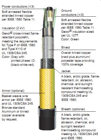
ill.17 VFD shielded power cable.]]
Electromagnetic Interference
Electromagnetic interference (EMI), also called electrical noise, is the unwanted signals generated by electrical and electronic equipment. EMI drive problems range from corrupted data transmission to electric motor drive damage. Modern drives using IGBT switches for motor frequency control are very efficient because of their high switching speed. Unfortunately the high-speed switching also results in much higher EMI being generated. All drive manufacturers detail installation procedures that must be followed in order to prevent excessive noise on both sides of the drive. Some of these noise suppression procedures include the following:
• Use a shielded power cable, such as the one shown in ill.17, to connect the VFD to the motor.
• Use a built-in or external EMI filter.
• Use twisted control wiring leads to provide a balanced capacitive coupling.
• Use shielded cable to return the noise current flowing in the shield back to the source, instead of through the signal leads.
• Maintain at least 8-inch separation between control and power wires in open air, conduit, or cable trays.
• Use a common-mode choke wound with multiple turns of both signal and shield.
• Use optical isolation modules for control signal communications
Inherent in all motor cables is line-to-line and line-to ground capacitance. The longer the cable, the greater is this capacitance. Electrical spikes occur on the outputs of PWM drives due to currents charging the cable capacitances. Higher voltages, such as 460 VAC, along with higher capacitances, result in larger current spikes. These spikes can shorten the lives of inverters and motors. For this reason cable length must be limited to that recommended by the manufacturer.
Grounding
ill.18 illustrates the general grounding requirements for a VFD. Proper grounding plays a key role in the safe and reliable operation of the VFD system. All electric motor drives, motors, and related equipment must meet the grounding and bonding requirements of NEC Article 250. The drive's safety ground must be connected to system ground.
Ground impedance must conform to the requirements of the NEC in order to provide equal potential between all metal surfaces and a low-impedance path to activate overcurrent devices and reduce electromagnetic interference.
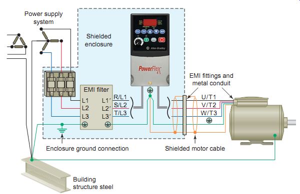
ill.18 General grounding requirements for a variable-frequency drive.
Building structure steel; Power supply system; Shielded enclosure; Shielded
motor cable; EMI fittings and metal conduit
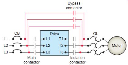
ill.19 Power circuit connection of a VFD bypass contactor. Enclosure
ground connection; EMI filter
Bypass Contactor
A bypass contactor is intended for use in case of a drive failure for short-time emergency service. A typical diagram of the power circuit connection of a VFD bypass contactor is shown in ill.19. The isolation contactor electrically isolates the drive during bypass operation and is mechanically and electrically interlocked with the bypass contactor to ensure that both cannot be closed at the same time. Upon a sensed malfunction of the VFD, the control circuit automatically opens the drive isolation contactor and closes the bypass contactor to keep the motor connected to the source.
When automatic transfer to bypass operation occurs, the motor continues to operate at full speed. The drive isolation contactor must be opened during closing of the bypass contactor so that AC power is not fed into the output of the VFD, causing damage. The automatic switch to bypass ensures no downtime and no interruption of service to critical loads. E.g, in HVAC applications, this allows heating or cooling to be maintained at all times.
Disconnecting Means
Safety in operation and maintenance dictates that all motor-operated equipment has a means of fully disconnecting the power supply. This is a requirement of National Electrical Code (NEC) and Occupational Safety and Health Administration (OSHA) regulations. As with starters, to reduce cost and size, most VFD manufacturers don’t provide a disconnect switch as part of their standard drive package. If the optional input disconnect is not specified, a separate switch or circuit breaker must be installed. Article 430.102 of the NEC includes requirements for disconnecting means for the motor itself and for the motor controller; both sets of requirements must be satisfied. The general rules that apply are as follows:
• Under 600 V, the controller disconnecting means must be within sight (and less than 50 ft according to definitions) of the motor controller as specified in Article 430.102(A).
• The controller is not required to be in sight from the motor.
• The controller disconnecting means shall also be permitted as the motor disconnecting means according to Article 430.102(B).
• The motor disconnecting means shall be in sight of the motor. See exceptions under Article 430.102(B) that would allow motor disconnecting means to be out of sight of the motor. These exceptions, if applicable, would allow one lockable disconnect to serve as both controller and motor disconnect while not in sight of the motor.
Motor Protection
VFDs can operate as motor protection devices along with their role as motor speed controllers. Some VFDs have short-circuit protection (usually in the form of fuses) already installed by the manufacturer, as shown in the VFD package of ill.20. The selection and sizing of these fuses is critical for semiconductor protection in the event of a fault. The manufacturer's recommendations must be followed in installing or replacing fuses for the VFD to assure fast operation of fuses in case of a fault.
In most drive applications the drive itself provides overload protection for the motor. However, the feeder cable can't be protected by VFD built-in protection. The motor drive provides protection based on motor name plate information that is programmed into it. Controllers incorporate many complex protective functions, such as:
• Stall prevention
• Current limitation and overcurrent protection
• Short-circuit protection
• Undervoltage and overvoltage protection
• Ground fault protection
• Power supply phase failure protection
• Motor thermal protection through sensing of the motor winding temperature
When a VFD is not approved for overload protection, or if multiple motors are fed from the drive, one or more external overload relays must be provided. The most common practice is to use a motor overcurrent relay that will protect all three phases and protect against single phasing.
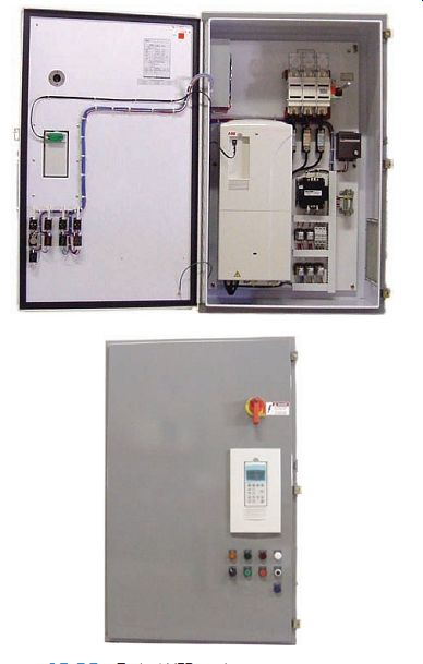
ill.20 Typical VFD package. manuf. Joliet Technologies Braking
With AC motors, there is excessive energy generated when the load drives the motor during deceleration, instead of the motor driving the load. This energy goes back into the drive and will result in an increasing DC bus voltage. If the bus voltage goes too high, the drive will be damaged.
Depending on design, a VFD can redirect this excess energy through resistors or back to the AC supply.
When dynamic braking is used, the drive connects a braking resistor across the DC bus, as shown in ill.21, to absorb the excess energy. For smaller horsepower motors, the resistance is built into the drive.
External resistance banks are used for larger-horsepower motors to dissipate the increased heat load.
Regenerative braking is similar to dynamic braking, except the excess energy is redirected back to the AC supply. VFDs designed to use regenerative braking are required to have an active front end to control regenerative current. With this option the diodes in the converter bridge are replaced with IGBT modules. The IGBT modules are switched by the control logic, and operate in both motoring and regenerative modes.
DC-injection braking is a standard feature on a number of variable-frequency drives. As the term implies, DC injection braking generates electromagnetic forces in the motor when the controller, in stop mode, injects direct cur rent into the stator windings-after it has cut off alternating current supply to two of the stator phases-thus turning off the normal rotating magnetic field. Most DC injection braking systems have the ability to adjust the length of time they will operate and the maximum torque they will apply. They generally begin braking when they detect that the motor is no longer receiving its run command and come equipped with hardware to prevent the motor from receiving another run command until the braking is finished.
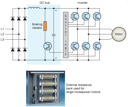
ill.21 Dynamic braking applied to a variable-frequency drive. External
resistance; bank used for larger-horsepower motors; DC bus Inverter
Ramping
Variable-frequency drives offer many of the same advantages as reduced-voltage and soft start starters. The timed speed ramp-up feature found in VFDs is similar to the soft start function of starters. However, the VFD timed speed ramp-up generally has a much smoother acceleration than soft starting, which is usually done in steps. Soft starting with a VFD reduces the frequency initially supplied to the motor and steps up the frequency over a preset period of time. VFDs with soft start capabilities have replaced many of the older types of reduced-voltage starters. While VFDs offer soft start capabilities, true soft start starters are not considered variable-frequency drives.
Ramping is the ability of a VFD to increase or decrease the voltage and frequency to an AC motor gradually. This accelerates and decelerates the motor smoothly, as shown in ill.22, with less stress on both the motor and connected load. Ramp-up is generally a smoother acceleration than the stepped increases used in soft starters. The length of time pre set for the speed ramp-up can be varied from a few seconds to 120 seconds or more, depending on the drive capabilities.
Timed ramp-down is a function of VFDs that provides smooth deceleration, bringing the motor to a full stop in a preset time. Acceleration and deceleration are separately programmable. Depending on drive parameters, ramp down times can vary from fractions of a second (when used with dynamic braking) to more than 120 seconds.
The ramp-down function is applied in processes that require smooth stops, but also require the process to stop within a given period of time.
Control Inputs and Outputs
ill.23 illustrates typical power and control inputs and output termination points found on VFDs. The three phase power source is connected at the line input terminals L1, L2, and L3 and the motor feed conductors are connected to the output motor terminals T1, T2, and T3.
The line and motor terminals pass through electronic circuitry so there is no direct connection between them, as with an across-the-line starter.
Most VFDs contain control terminal strips for external connection for both digital and analog inputs and outputs.
The number and types of inputs and outputs will vary with the complexity of the drive and serve as a means of comparison between manufacturers of VFDs. Variable frequency drive inputs and outputs are either digital or analog signals. Digital inputs and outputs have two states (either on or off), while analog inputs and outputs have many states that vary across a range of values.
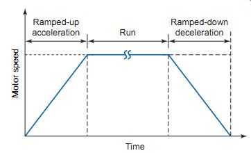
ill.22
Variable-frequency drive ramping functions. Ramped-up acceleration; Ramped-down
deceleration; Run Time Motor speed
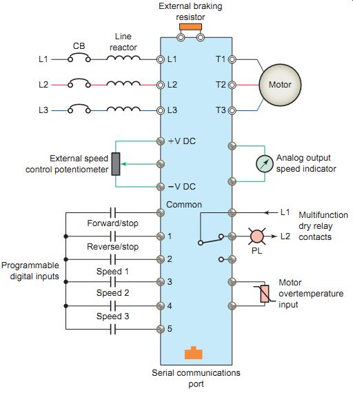
ill.23 Typical VFD control inputs and outputs.
[[L1 common T3 External braking resistor L2 L3 External speed control potentiometer Programmable digital inputs Forward/stop Reverse/stop Speed 1 Speed 2 Serial communications port Motor over temperature input Multifunction dry relay contacts Analog output speed indicator Speed 3 Motor]]
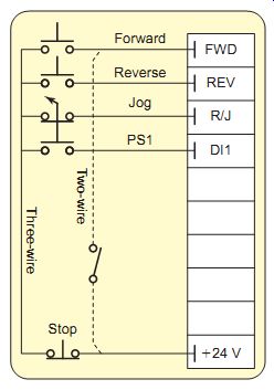
ill.24 Input digital connections for two-wire or three-wire control
with stop, forward, reverse, and jogging functions.
DIGITAL INPUTS
Digital inputs are used to interface the drive with devices such as push buttons, selector switches, relay contacts, and PLC digital output modules. Each digital input may have a preset function assigned to it, such as start/stop, forward/reverse, external fault, and preset speed selections. For example, if a motor has to operate at three different speeds, a relay or switch contact could be made to close and send signals to separate digital inputs points that would change the motor speed to the preset value.
ill.24 shows typical input digital connections for two-wire or three-wire control with stop, forward, reverse, and jogging functions. Because VFDs are electronic devices, they can have only one phase rotation output at a time. Therefore, interlocking, as required on electromechanical devices, is not required for VFD for ward/reverse operations. Inputs can also be programmed for two- or three-wire control to accommodate either maintained or momentary start methods. Note that the control logic is determined and executed by the program within the drive and not by the hard-wiring arrangement of the input control devices.
Digital/relay outputs. Digital/relay outputs are two position signals (on/off) sent by the VFD to devices such as pilot lights, alarms, auxiliary relays, solenoids, and PLC digital input modules. Digital outputs have a volt age potential (e.g., 24 V DC) coming from them. Relay outputs, which are known as "dry" contacts, switch some thing external, closing or opening another potential. Relay outputs are normally rated for both AC and DC voltages.
Analog inputs . Analog inputs are used to interface the drive with an external 0- to 10-V DC or 4- to 20-mA signal- For example, a speed setpoint from an external speed control potentiometer.
Analog outputs . Analog outputs are modulating signals sent by the VFD to a device such as a meter that could display speed or current.
====
Induction motor adjustable speed duty SERIAL NO.
TYPE KAF ENCLOSURE TEAO FRAME 6811 DRIVE END BRG SKF 6319 LUBRICATION GREASE LUBRICANT OPP. DRIVE END BRG SKF 6319 LUBRICATION GREASE LUBRICANT OIL PRESSURE TO PSI OIL FLOW TO GPM/BRG AMB. TEMP. (°C) 40 MAX MIN
MANUFACTURING DATE:
SUITABLE FOR OPERATION FROM 120 TO 1200 RPM AT CONSTANT TORQUE SUITABLE FOR OPERATION FROM 1200 TO 1800 RPM AT CONSTANT POWER SUITABLE FOR OPERATION FROM TO RPM AT VARIABLE TORQUE CONSTANT VOLTS / HERTZ TO 1200 RPM MODEL 5KAF POWER 400HP RPM BASE 1200 AMPERES 368 SINE VOLTS 575 V (MAX.) 575 PHASE 3 HERTZ 40 EFF. 0.9567 PF. 0.85 SERVICE FACTOR 1.15 SINE 1.0 ASD INSULATION CLASS F MAX. TEMP. RISE 80 °C AT SF TIME RATING CONTINUOUS INVERTER TYPE IGBT-PWM ALTITUDE 1000 (M) STATOR BY
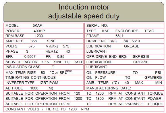
ill.25 Entering motor nameplate data.
====
Motor Nameplate Data
Motor specifications are programmed into the VFD to ensure optimum drive performance as well as adequate fault and overload protection. This may include the following items found on the nameplate, as illustrated in ill.25, or derived through measurements:
• Frequency (hertz)--Nameplate frequency required by the motor to achieve base speed. The default value is normally 60 Hz.
• Speed (rpm)--Nameplate maximum speed at which the motor should be rotated.
• Full-load current (amperes)--Nameplate maxi mum current that the motor may use. Full-load amperes ( FLA) and full-load current (FLC) are the same as the motor nameplate current.
• Supply voltage (volts)--Nameplate voltage required by the motor to achieve maximum torque.
• Power rating (horsepower or kilowatts) - Name plate rating of motors manufactured in the United States are generally rated in horsepower (hp). Equipment manufactured in Europe is generally rated in kilowatts (kW). Horsepower can be converted as follows: 1 hp = 0.746 kW.
• Motor magnetizing current (amperes)--Current that the motor draws when operating with no load at nameplate rated voltage and frequency. If not specified, it can be measured using a true-RMS clamp-on ammeter.
• Motor stator resistance (ohms)--DC resistance of the stator between any two phases. If not specified, it can be measured with an ohmmeter.
Derating
Derating a VFD means using a larger than normal drive in the application. Derating is required when a drive is to be operated outside the normal operating range specified by the manufacturer. Most manufacturers provide derating figures when the drive is to be operated outside the specified temperature, voltage, and altitude. As an example, derating must be considered when the drive is installed at high altitude, greater than 1000 meters (3300 ft.). The cooling effect of the drive is deteriorated because of the reduced density of the air at high altitudes.
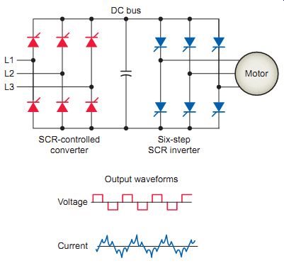
ill.26 Simplified circuit of a voltage-source inverter (VSI). DC bus
SCR-controlled converter Six-step SCR inverter Output waveforms Voltage
Current
Motor
Types of Variable-Frequency Drives
The evolution of AC drive technology has seen many changes in a relatively small time frame. As a result, newer drives with greater functionality are now avail able. Most variable-frequency drives manufactured today are pulse-width modulation drives that convert the 60-Hz line power to direct current, then pulse the output volt age for varying lengths of time to mimic an alternating current at the frequency desired. Many older VFDs were distinguished by the type of inverter circuitry used in the drive. Two earlier types of drives were the voltage-source inverter and the current-source inverter .
ill.26 shows a simplified circuit of one type of voltage source inverter (VSI), also called variable-voltage inverter (VVI). This inverter uses a silicon controlled rectifier (SCR) converter bridge to convert the incoming AC voltage into DC. The SCRs provide a means of con trolling the value of the rectified DC voltage. The energy storage in the DC link between the converter and inverter consists of capacitors. The inverter section utilizes six SCR switches. The control logic (not shown) uses a microprocessor to switch the SCRs on and off, providing a variable voltage and frequency to the motor. This type of switching is often referred to as six-step because it takes six 60° steps to complete one 360° cycle. Although the motor prefers a smooth sine wave, a six-step output can be satisfactorily used. The main disadvantage is torque pulsation, which occurs each time an SCR is switched.
The pulsations can be noticeable at low speeds as speed variations in the motor. These speed variations are some times referred to as cogging. The nonsinusoidal current waveform causes extra heating in the motor, requiring a motor derating. Voltage-source inverter drives can operate any number of motors up to the total rated horsepower of the drive.
With a current-source inverter, the DC power supply is con figured as a current source rather than a voltage source.
These drives employ a closed-loop system that monitors the actual speed of the motor and compares it with the pre set reference speed, creating an error signal that is used to increase or decrease the current to the motor. ill.27 shows the simplified circuit of a current-source inverter (CSI). The converter is connected to the inverter through a large series inductor. This inductor opposes any change in current and is of a sufficiently high inductance value that direct current is constrained to be almost constant. As a result, the output produced is almost a square wave of cur rent. Current-source inverters are used for large drives- about 200 hp-because of their simplicity, regeneration braking capabilities, reliability, and lower cost. Since current-source inverters monitor the actual motor speed, they can be used to control only a single corresponding motor with characteristics that match the drive.
PID Control
Most VFD applications require the AC motor to run at a specific speed as set by the keypad, speed potentiometer, or analog input. Some drives provide an alternative option that allows precise process control through a setpoint controller or PID mode of operation. Many variable-frequency drives come equipped with a built-in proportional-integral-derivative (PID) controller. The PID loop is used to maintain a process variable, such as speed, as illustrated in ill.28. The desired speed, or setpoint, and the actual speed values are input to a summation point. These two signals are opposite in polarity and yield a zero error or deviation whenever the desired speed equals the actual speed. If the two signals differ in value, the error signal will have a positive or negative value, depending on whether the actual speed is greater or less than the desired speed. This error signal is input to the PID controller. The terms proportional, integral, and derivative describe three basic mathematical functions then applied to the error signal. The PID output reacts to the error and outputs a frequency to try to reduce the error value to zero. The controller's job is to make the speed adjustments quickly, with a minimum of overshoot or oscillations. Tuning the PID controller involves gain and time adjustments designed to improve performance and result in a fast response with a minimum overshoot, allowing the motor to settle in quickly to the new speed.
Some drives have a PID autotune function designed to ease the tuning process.
Parameter Programming
The main drive program is contained in the processor's firmware and not normally accessible to the VFD user. A parameter is a variable associated with the operation of the drive that can be programmed or adjusted. Parameters provide a degree of adjustment so that the user can customize the drive to suit specific motor and driven equipment requirements. The number of parameters can range from 50, for small basic drives, to over 200 for larger, more complex drives. Some VFDs provide upload/download and parameter copy capability. Common adjustable parameters include the following:
• Preset speeds
• Minimum and maximum speeds
• Acceleration and deceleration rates
• Two- and three-wire remote control modes
• Stop modes: ramp, coast, DC injection
• Automatic torque boost
• Current limit
• Configurable input jog
• V/Hz settings
• Carrier frequency
• Program password
VFDs come with factory default settings for most parameters that are more conservative in nature. The default value settings simplify the start-up procedure.
However, parameters for motor nameplate data are not factory-set (unless a matched drive and motor has been purchased) and must be entered in the field. In general there are three types of parameters:
• Tunable on the l y -Parameters can be adjusted or changed while the drive is running or stopped.
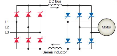
ill.27 Simplified circuit of a current-source inverter (CSI). Series
inductor
Response Original speed Desired new speed Desired speed (setpoint) Actual speed Deviation (error) PID controller Controller output Proportional circuit Integral circuit Derivative circuit
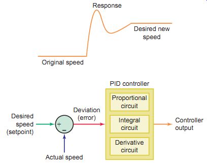
ill.28 PID loop.
• Configurable -Parameters can be adjusted or changed only while the drive is stopped.
• Read only-Parameters cannot be adjusted.
ill.29 shows an integral keypad with an LED display used to program and operate a small drive locally.
The display shows either a parameter number or a parameter value. The drive's parameter menu outlines what the parameter number represents, and what numerical selections or options for the parameter are available. Parameter menu formats vary between make and model. This drive has two kinds of parameters: program parameters (P-00 through P-64), which con figure the drive operation, and display parameters (d-00 through d-64), which display information. Examples of program parameters include:
- P-00 minimum speed -Use this parameter to set the lowest frequency the drive will output. Default setting is 0.
- P-01 maximum speed -Use this parameter to set the highest frequency the drive will output. Default set ting is 60 Hz.
- P-02 motor overload current -Set this parameter to the motor nameplate full-load ampere rating. Default setting is 100 percent of the rated drive current.
- P-30 acceleration time -Use this parameter to define the time it will take the drive to ramp up from 0 Hz to maximum speed. Default setting is 5.0 seconds.
Examples of display parameters include:
- d-00 command frequency -This parameter represents the frequency that the drive is commanded to output.
- d-01 output frequency -This parameter represents the output frequency at the motor terminals.
- d-02 output current -This parameter represents the motor current.
- d-03 bus voltage -This parameter represents the DC bus voltage level.
ill.29 Integral keypad with an LED display used to program and operate
a small drive locally.
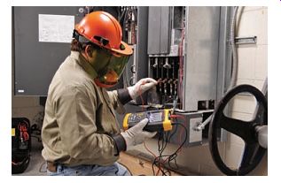
ill.30 Taking measurements on a VFD. Fluke, www.fluke.com.
Diagnostics and Troubleshooting
Most VFDs come equipped with self-diagnostic controls to help trace the source of problems. Always observe the following precautions when troubleshooting the drive:
• Stop the drive.
• Disconnect, tag, and lock out AC power before working on the drive.
• Verify that there is no voltage present at the AC input power terminals ( ill.30).
It's important to remember that DC bus capacitors retain hazardous voltages after input power has been disconnected. Therefore, wait 5 minutes for the DC bus capacitors to discharge once power has been disconnected. Check the voltage with a voltmeter to ensure that the capacitors have discharged before touching any internal components.
Problem indicators may include the following:
- LEDs provide a quick indication of problems.
- Normally, a steady glowing light means everything is running properly. Flashing yellow or red lights indicate a problem with the drive that should be checked.
Consult the operator's manual for the specific drive to determine what a particular flashing light means.
Alarms indicate conditions that may affect drive operation or application performance. They are cleared automatically when the condition that caused the alarm is no longer present. Configurable alarms alert the operator to conditions that, if left untreated, may lead to a drive fault. The drive continues to operate during the alarm condition, and the alarms can be enabled or disabled by the programmer or operator.
Nonconfigurable alarms alert the operator of conditions caused by improper programming and prevent the drive from starting until the problem is resolved.
These alarms can never be disabled.
Fault parameters settings indicate conditions within the drive that require immediate attention. The drive responds to a fault by coasting to a stop and turning off output power to the motor. Auto-reset faults reset automatically if, after a preset time, the condition that caused the fault is no longer present. The drive then restarts. Non-resettable faults may require drive or motor repair; the fault must be corrected before it can be cleared. User-configurable faults can be enabled and disabled to enunciate or ignore a fault condition.
Fault queues normally retain a history of faults. Typically, queues hold only a limited number of entries; there fore, when the queue is full, older faults are discarded when new faults occur. The system typically assigns a timestamp to the fault so that programmers or operators can determine when a fault occurred relative to the last drive power-up.
A complete listing of all the different types of faults and the appropriate corrective actions can typically be found in the operator's manual for a specific drive. The following are examples of typical fault codes and corrective action:
===
- Display Code Fault Description Fault Cause Corrective Action
- CF Undervoltage Low input line. Temporary loss of input line.
- Check input line to verify voltage is within operating specifications.
- OL Motor overload Excessive driven load. Reduce the load.
- J1, J2, or J2 Ground short Phase A, B, or C. Verify output wiring is correct.
- Verify output phase is not grounded.
- Verify motor is not damaged.
- OH Over-temperature; Operating environment is too hot.
- Fan is blocked or not operating.
- Excessive driven load.
- Verify the ambient temperature is less than 50° C.
- Verify clearance above and below drive.
- Check for fan obstruction.
- Reduce the carrier frequency.
- Reduce the load.
===
QUIZ:
1. Compare the torque characteristics of constant, variable, and shock loads.
2. Explain the function of reactors that are connected in series with the line and load side of a VFD.
3. List the factors that need to be taken into account in selecting the location for an electric motor drive.
4. What is the purpose of a VFD enclosure?
5. What is the function of a drive's operator interface?
6. How are the effects of electromagnetic interference minimized in a VFD installation?
7. In addition to line losses, why must cable lengths between a PWM drive and motor be kept to a minimum?
8. Why is proper grounding required for the safe and reliable operation of a VFD system?
9. A bypass contactor working in conjunction with an isolation contactor is utilized in certain VFD installations. What purpose is served by this combination of contactors and how do they work together to achieve this?
10. Outline the basic code requirement for a drive's controller and motor disconnecting means.
11. Summarize the types of built-in protective functions that can be programmed into a variable-speed drive.
12. Compare the operation of dynamic, regenerative, and DC-injection VFD braking systems.
13. Ramped acceleration and deceleration are two key features of VFDs. Give a brief explanation of how each is achieved.
14. Compare digital and analog input and output drive control signals.
15. List typical preset functions that digital inputs may have assigned to them.
16. Why is forward/reverse interlocking not required on VFDs?
17. Compare the manner in which the control logic is executed in a hard-wired electromagnetic starter and a VFD.
18. Explain the term dry contact as it relates to a drive's relay output.
19. List typical motor nameplate data that may be required to be programmed into the VFD.
20. Explain the term derating as it applies to a VFD and list factors that might require a drive to be derated.
21. Compare PWM, VVI, and CSI variable-frequency drives.
22. Outline how setpoint speed is maintained in a PID control loop.
23. Explain the term parameter as it applies to the VFD.
24. List several common adjustable parameters associated with AC drives.
25. What is the difference between program and display parameters?
26. What potential safety hazard is associated with DC bus capacitors?
27. When LEDs are used for problem indicators, what does a steady glow indicate compared to a flashing one?
28. Compare the operation of autoreset, nonresettable, and user-configurable fault parameters.
29. Explain the term fault queues as it applies to VFDs.