AMAZON multi-meters discounts AMAZON oscilloscope discounts
1 Some General Perspectives
2 Operating Modes
3 Motor, Enclosure, and Controller Types
4 System Design: Load Requirements • Environmental Requirements • Electrical Source Options • Preliminary System Design • System Ratings • System Data Acquisition • Engineering Studies • Final System Design • Field Testing Further Information
A major application of electric energy is in its conversion to mechanical energy. Electromagnetic, or "EM" devices designed for this purpose are commonly called "motors." Actually the machine is the central component of an integrated system consisting of the source, controller, motor, and load. For specialized applications, the system may be, and frequently is, designed as a integrated whole. Many household appliances (e.g., a vacuum cleaner) have in one unit, the controller, the motor, and the load.
However, there remain a large number of important stand-alone applications that require the selection of a proper motor and associated control, for a particular load. It’s this general issue that is the subject of this section.
The reader is cautioned that there is no "magic bullet" to deal with all motor-load applications. Like many engineering problems, there is an artistic, as well as a scientific dimension to its solution. Likewise, each individual application has its own peculiar characteristics, and requires significant experience to manage. Nevertheless, a systematic formulation of the issues can be useful to a beginner in this area of design, and even for experienced engineers faced with a new or unusual application.
1 Some General Perspectives
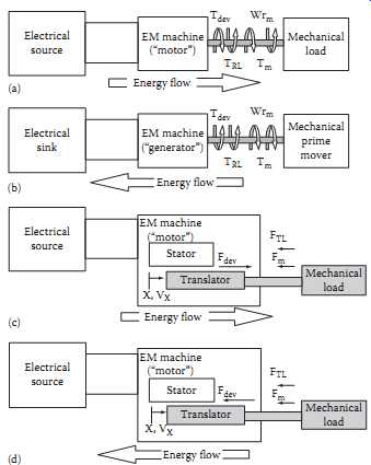
FIG. 1 Motor and generator sign conventions for EM machines. (a) The EM rotational
machine; motor convention. (b) The EM rotational machine; generator convention.
(c) The EM translational machine; motor convention. (d) The EM translational
machine; generator convention.
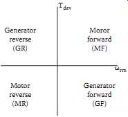
FIG. 2 Operating modes.
Consider the general situation in FIG. 1a. The flow of energy through the system is from left to right, or from electrical source to mechanical load. Also, note the positive definitions of currents, voltages, speed, and torques. These definitions are collectively called the "motor convention," and are logically used when motor applications are under study. Likewise, when generator applications are considered, the sign conventions of FIG. 1b (called generation convention) will be adopted. This means that variables will be positive under "normal" conditions (motors operating in the motor mode, generators in the generator mode), and negative under some abnormal conditions (motors running "backwards," for example). Using motor convention:
Tdev is the EM torque, produced by the motor, Nm Tm is the torque absorbed by the mechanical load, including the load losses and that used for useful mechanical work, Nm TRL is the rotational loss torque, internal to the motor, Nm T T T m m RL ' = + is equivalent load torque, Nm J is the mass polar moment of inertia of all rotating parts, kg-m^2
omega_rm is the angular velocity of rotating parts, rad/s
Observe that whenever T T dev m > ' , the system accelerates; if T T dev m < ' , the system decelerates. The sys tem will inherently seek out the equilibrium condition of T T dev m = ' , which will determine the running speed. In general, the steady state running speed for any motor-load system occurs at the intersection of the motor and load torque-speed characteristics, i.e., where T T dev m = ' . If T T dev m > ' , the system is accelerating; for T T dev m < ' , the system decelerates. Thus, torque-speed characteristics for motors and loads are necessary for the design of a speed (or position) control system.
The corresponding system powers are:
Pdev = Tdev omega_rm is the EM power, converted by the motor into mechanical form, W Pm = Tm omega_rm is the power absorbed by the mechanical load, including the load losses and that used for useful mechanical work, W PRL = TRL omega_rm is the rotational power loss, internal to the motor, W
2 Operating Modes
Equation 1 implies that torque and speed are positive. Consider positive speed as "forward," meaning rotation in the "normal" direction, which should be obvious in a specific application. "Reverse" is defined to mean rotation in the direction opposite to "forward," and corresponds to omega_rm < 0. Positive EM torque is in the positive speed direction. Using motor convention, first quadrant operation means that (1) speed is positive ("forward") and (2) Tdev is positive (also forward), and transferring energy from motor to load ("motoring"). There are four possible operating modes specific to the four quadrants of FIG. 2. In any application, a primary consideration is to determine which of these operating modes will be required.
3 Motor, Enclosure, and Controller Types
The general types of enclosures, motors, and controllers are summarized in Tables 1 - 3.
4 System Design
The design of a proper motor-enclosure-controller system for a particular application is a significant engineering problem requiring engineering expertise and experience. The following issues must be faced and resolved.
4.1 Load Requirements
1. The steady-state duty cycle with torque-speed (position) requirements at each load step.
2. What operating modes are required.
3. Dynamic performance requirements, including starting and stopping, and maximum and minimum accelerations.
4. The relevant torque-speed (position) characteristics.
5. All load inertias (J).
6. Coupling options (direct drive, belt-drive, gearing).
7. Reliability of service. How critical is a system failure?
8. Future modifications.
===
TABLE 1 General Enclosure Types
Types Open Drip-proof Splash-proof Semi-guarded Weather protected Type I Type II Totally enclosed Non-ventilated Fan-cooled Explosion-proof Dust-ignition-proof Water-proof Pipe-ventilated Water-cooled Water-air-cooled Air-to-air-cooled Air-over-cooled See NEMA Standard MG 1.1.25-1.1.27 for definitions.
====
TABLE 2 General Motor Types Type DC motors (commutator devices) Permanent magnet field Wound field Series Shunt Compound AC motors Single-phase Cage rotor Split phase Resistance-start Capacitor start Single capacitor (start-run) Capacitor start/capacitor run Shaded pole Wound rotor Repulsion; Repulsion start/induction run Universal Synchronous Hysteresis Three-phase Synchronous Permanent magnet field Wound field Induction Cage rotor NEMA Design A,B,C,D,F Wound rotor See NEMA Standard MG 1.1.1-1.1.21 for definitions.
====
TABLE 3 General Motor Controllers
Type
DC motor controllers Electromechanical Armature starting resistance; rheostat field control Power electronic drive Phase converters: 1, 2, 4 quadrant drives Chopper control: 1, 2, 4 quadrant drives AC motor controllers Single-phase Electromechanical Across-the-line: protection only Step-reduced voltage Power electronic drive Armature control: 1, 2, 4 quadrant drives Three-phase induction Cage rotor Electromechanical Across-the-line: protection only Step-reduced voltage Power electronic drive (ASDs) Variable voltage source inverter Variable current source inverter Chopper voltage source inverter PWM voltage source inverter Vector control Wound rotor Variable rotor resistance Power electronic rotor power recovery Three-phase synchronous Same as cage rotor induction Brushless DC control
===
4.2 Environmental Requirements
1. Ambient atmospheric conditions (pressure, temperature, humidity, content)
2. Indoor, outdoor application
3. Wet, dry location
4. Ventilation
5. Acceptable acoustical noise levels
6. Electrical/mechanical hazards to personnel
7. Accessibility for inspection and maintenance
4.3 Electrical Source Options
1. DC-AC
2. If AC, single- and/or three-phase
3. Voltage level
4. Frequency
5. Capacity (kVA)
6. Protection options
7. Power quality specifications
4.4 Preliminary System Design
Based on the information compiled in the steps above, select an appropriate enclosure, motor type, and controller. In general, the enclosure entries, reading from top to bottom in TABLE 1, are from simplest (and cheapest) to most complex (and expensive). Select the simplest enclosure that meets all the environmental constraints. Next, select a motor and controller combination from Tables 2 and 3. This requires personal experience and/or consulting with engineers with experience relevant to the application.
In general, DC motors are expensive and require more maintenance, but have excellent speed and position control options. Single-phase AC motors are limited to about 5 kW, but may be desirable in locations where three-phase service is not available and control specifications are not critical.
Three-phase AC synchronous motors are not amenable to frequent starting and stopping, but are ideal for medium and high power applications which run at essentially fixed speeds. Three-phase AC cage rotor induction motors are versatile and economical, and will be the preferred choice for most applications, particularly in the medium power range. Three-phase AC wound rotor induction motors are expensive, and only appropriate for some unusual applications.
The controller must be compatible with the motor selected; the best choice is the most economical that meets all load specifications. If the engineer's experience with the application under study is lacking, two or more systems should be selected.
4.5 System Ratings
Based on the steps above, select appropriate power, voltage, and frequency ratings. For cyclic loads, the power rating may tentatively be selected based on the "rms horsepower" method (calculating the rms power requirements over the load cycle).
4.6 System Data Acquisition
Request data from at least two vendors on all systems selected in the steps above, including:
• Circuit diagrams
• Performance test data
• Equivalent circuit values, including inertia constants
• Cost data
• Warranties and guarantees
4.7 Engineering Studies
Perform the following studies using data from the system data acquisition step above.
1. Steady state performance. Verify that each candidate system meets all steady state load requirements.
2. Dynamic performance. Verify that each system meets all dynamic load requirements.
3. Load cycle efficiency. Determine the energy efficiency over the load cycle.
4. Provide a cost estimate for each system, including capital investment, maintenance, and annual operating costs.
5. Perform a power quality assessment.
Based on these studies, select a final system design.
4.8 Final System Design
Request a competitive bid on the final design from appropriate vendors. Select a vendor based on cost, expectation of continuing technical support, reputation, warranties, and past customer experience.
4.9 Field Testing
Whenever practical, customer and vendor engineers should design and perform field tests on the installed system, demonstrating that it meets or exceeds all specifications. If multiple units are involved, one proto unit should be installed, tested, and commissioned before delivery is made on the balance of the order.
Further Information:
The design of a properly engineered motor-controller system for a particular application requires access to several technical resources, including standards, the technical literature, manufacturers' publications, textbooks, and handbooks. The following section provides a list of references and resource material that the author recommends for work in this area. In many cases, more recent versions of publications listed are available and should be used.
Organizations:
American National Standards Institute (ANSI), 1430 Broadway, New York, 10018.
Institute of Electrical and Electronics Engineers (IEEE), 445 Hoes Lane, Piscataway, NJ 08855.
International Organization for Standardization (ISO) 1, rue de Varembe, 1211 Geneva 20, Switzerland.
American Society for Testing and Materials (ASTM), 1916 Race Street, Philadelphia, PA 19103.
National Electrical Manufacturers Association (NEMA), 2101 L Street, NW, Washington, DC 20037.
National Fire Protection Association (NFPA), Batterymarch Park, Quincy, MA 02269.
The Rubber Manufacturers Association, Inc., 1400 K Street, NW, Suite 300, Washington, DC 20005.
Mechanical Power Transmission Association, 1717 Howard Street, Evanston, IL 60201.
Standards ANSI/IEEE Std 304-1982, Test Procedure for Evaluation and Classification of Insulation Systems for DC Machines.
ANSI/IEEE Std 115-1983, Test Procedures for Synchronous Machines.
ANSI/IEEE Std 100-1984, IEEE Standard Dictionary of Electrical and Electronics Terms.
ANSI/IEEE Std 114-1984, Test Procedure for Single-Phase Induction Motors.
ANSI/IEEE Std 117-1985, Standard Test Procedure for Evaluation of Systems of Insulating Materials for Random-Wound AC Electric Machinery.
ANSI/NFPA 70-1998, National Electrical Code.