AMAZON multi-meters discounts AMAZON oscilloscope discounts
An overhead transmission line (OHTL) is a complex electric/mechanical system designed to transfer electricity between power substations. Structural elements must safely and reliably support current carrying conductors while providing the necessary separation between individual line phases and the ground. Transmission lines are composed of many individual elements consisting of a variety of materials with a wide range of mechanical properties. The difference in performance of these components is evident in their mechanical characteristics, such as the following:
• Flexible vs. rigid
• Ductile vs. brittle
• Variant dispersions of strength
• Wear and deterioration occurring at different rates
Transmission lines consist of two separate structure systems: the structural support system comprised of towers/poles and foundations, and the wire system comprised of conductor, shield wire, insulators, and hardware. The structural support system is required to provide support for the wire system while accommodating ice and wind acting on both the structural support system and the wire system.
This discussion addresses the types of design practices normally required for the structural support system.
1. Transmission Line Design Practice
Traditional and modern transmission line design follows several common practices. These include providing overhead conductor and shield (ground) wire configurations that meet minimum clearance requirements based on the voltage level of the line as required by the National Electrical Safety Code (NESC) (IEEE, 2006), as well as other applicable codes. The NESC and similar codes provide specified requirements for the separation of the following:
• Energized parts from other energized parts
• Energized parts from the support structure and other objects located along the right-of-way
• Energized parts aboveground
Transmission line loads can be classified as weather-related, accidental, or caused by construction or maintenance activities. Analysis of weather-related events is typically governed by national or regional codes (such as NESC), while accidental, construction, and maintenance events are primarily developed by utilities for the specific needs and conditions of their service territory, with many based on commonly accepted practices. Traditional design includes some probabilistic evaluations of weather-related events but relies mostly on a deterministic process from successful experience. Load cases for accidental events such as component breakage, wear or fatigue, structure failure from natural disasters or terrorism, and other unforeseen events are analyzed to provide designs that minimize their consequences to the OHTL as a whole and prevent an uncontrolled cascade-type system loss. These cases are considered special security requirements. Evaluations for safety requirements are applied to more predictable operational, construction, and maintenance events where calculated loads are analyzed using both regulations and standard codes of practice.
OHTLs are suspended and spaced to produce code-required conductor and shield wire clearances.
Resultant structure loads are influenced by not only the sag/tensions but also variable meteorological conditions that act in both transverse and longitudinal directions. NESC provides requirements to evaluate these conditions that include combined ice and wind loading criteria divided into three distinct loading districts: heavy, medium, and light. Each district defines regional climate variations with different combinations of radial ice thickness, wind pressure, and ambient temperature. NESC requirements also give extreme wind loading, providing basic wind speeds that must be adjusted (with consideration for height and gust response) separately for both the wire and the support structure systems. The final NESC load criterion that must be considered is extreme ice with concurrent wind. The NESC provides loading maps for each of these requirements.
In recent years, NESC has adopted reliability-based design (RBD) using the load resistance factor design (LRFD) approach and now includes load factors and strength factors. Load factors consider the uncertainty of the load event, the possibility the design loads will be exceeded, the grade of construction, and structure function. Load factors, though, do not consider the type of material. Strength factors at installation are provided by NESC and take into consideration the type of material and deterioration characteristics.
The design of a transmission line normally includes the following steps:
1. The utility prepares an agenda of loading events consisting of
a. Mandatory regulations from the NESC and other codes
b. Climatic events assumed representative of the line's specific location
c. Contingency (security) loading events of interest, i.e., broken conductor
d. Safety requirements and expectations, i.e., maintenance loads, stringing, etc.
Each of these loading events includes load factors to cover associated uncertainties to produce a set of factored design loads.
2. A ruling span is identified based on the sag/tension requirements for the preselected conductor.
3. Structure type is selected based on past experience, utility standards, recommendations of potential structure suppliers, terrain and construction issues, economics, and long-term maintenance concerns.
4. Ultimate design loads resulting from the ruling span are applied statically on components in the longitudinal, transverse, and vertical directions, and the structure is either designed by deterministic or reliability-based methods.
5. Using the loads and structure configuration, ground line reactions are calculated and used to complete the foundation design. Foundations are also designed using either deterministic or RBD methods.
6. The ruling span line configuration is adjusted to fit the actual right-of-way profile.
7. Structure/foundation designs are modified to account for variation in actual span lengths, changes in elevation, and running angles.
Traditional line design views the support structure as an isolated element supporting half span of over head conductors and shield wires on either side of the structure. Using ruling span assumptions with similar span lengths and suspension supports in the tension section yields somewhat accurate results.
Ruling span assumptions become less accurate in conditions where span lengths vary in hilly terrain.
Under these conditions, sag differences can be much different from the ruling span assumptions. It should also be noted that inaccuracies when using ruling span assumptions under high temperature, unbalanced ice, and broken wire conditions are also evident. Thus, modern line design practice using computer-based programs enables a more accurate development of loads at each structure location, clearance to ground, and clearance to structure.
Inasmuch as structure types are available in a wide variety of configurations, materials, and costs, several iterations would normally be attempted in search of the most cost-effective line design based on total installed costs.
While traditional deterministic design using static loads is a convenient mathematical approach, it is obviously not representative of the real-world exposure of the structural support system. OHTLs are tens of yards wide and miles long and usually extend over many widely variant topographical and climatic zones, each capable of delivering unique events consisting of magnitude of load at a probability of occurrence. That component along the right-of-way that has the highest probability of occurrence of failure from a loading event becomes the weak link in the structure design and establishes the reliability level for the total line section. Since different components are made from different materials that have different response characteristics and that wear, age, and deteriorate at different rates, it is to be expected that the weak link
• Will likely be different in different line designs
• Will likely be different in different site locations within the same line
• Can change from one component to another over time
1.1 Transmission Line Support Structures
Structures used for transmission lines come in a wide range of materials, shapes, and configurations.
Typical materials and shapes include but are not limited to the following:
• Steel (hot-rolled angles, plates, formed plate polygonal tubular members)
• Aluminum (extruded shapes, plates)
• Concrete (static cast, spun cast with pre- or post-tension strands)
• Wood (glue-laminated poles and crossarms, poles, crossarms)
• Fiber-reinforced polymer (FRP) (crossarms, poles) There are a variety of configurations used for transmission structures. These include the following:
• Lattice towers (steel, aluminum) (ASCE, 2000)
• Single shaft poles (steel, wood, FRP, concrete) (IEEE, 1991; ASCE, 2003; Magee, 2006)
• H-frame structures (steel [latticed and tubular], wood)
• Guyed structures (steel [latticed and tubular], concrete) (ASCE, 1997)
• Framed structures (tubular)
Utility standards, operational and maintenance procedures, installed cost, lifetime cost, structure performance, right-of-way access and terrain, and aesthetics are just some of the issues that must be considered when selecting a structure type for a transmission line. Long-term considerations for future upgrades may also impact final selection of material and structure configuration.
1.2 Transmission Line Foundations
The function of a transmission foundation is to transfer applied steady-state and transient loads into the surrounding soil and rock while limiting structure movement. Loads are conveyed to the subsurface at the ground line interface, where either a separate foundation system is installed and connected to the structure or the above-grade structure is directly buried and backfilled. Foundation systems can be categorized in the following general groups:
• Spread foundations (steel grillages and reinforced concrete)
• Reinforced concrete drilled shafts
• Direct embedment poles (steel, wood, concrete)
• Driven piles (steel, wood, concrete)
• Anchors (various materials and configurations)
Detailed descriptions of transmission foundation systems are provided by the Institute of Electrical and Electronics Engineers (IEEE) Standards 691 and 977 (IEEE, 2001, 2010).
Spread foundations typically support lattice tower structures using either a reinforced concrete or a prefabricated steel grillage footing for each leg. Guyed lattice structures use a combined system of one or more spread footings in conjunction with guy anchors.
Because of their ability to resist uplift loads, compression loads, and lateral overturning forces, drilled shaft foundations are used to support a wide variety of transmission system structures, including lattice towers, single shaft steel poles, and framed pole structures. Drilled shafts are connected to lattice towers typically with bent or angled structural steel angles embedded into the reinforced concrete foundation. Most often, single pole and framed pole structures (and occasionally lattice
towers) include steel base plates at the bottom of the structure which are fixed to the foundation via steel anchor bolts in either a circular or rectangular pattern around the inside perimeter of the shaft.
These anchor bolts can be partially or fully extended within the drilled shaft and can be made part of the reinforcement cage or be contained within and separate from reinforcement. Drilled shaft foundations are typically uniformly cylindrical but can be drilled with tapers, uniformly variable shaft sections, or belled bottoms.
Lower voltage lines with lighter loading conditions can be supported with single pole or frame pole structures directly embedded within a drilled shaft hole, then backfilled with a variety of natural and man-made materials. The annulus space around the pole can be filled with concrete, compacted native soil, or slurried aggregates either with or without cement. Permanent steel casing is sometimes incorporated with direct embedment foundations where groundwater is present.
Piles (or more commonly piles in closely spaced groups) are either mechanically driven or vibrated into the ground to support all types of transmission structures. Generally this is done where ground conditions are soft enough to accept the concrete, steel, or wood piles. Structures are fixed to pile groups often with cast-in-place reinforced concrete caps. Lightly loaded wood poles can be fixed to single steel or concrete piles via mechanical connection.
Foundation anchors for transmission structures encompass a large variety of types and materials and are used to directly support guyed structures or are encased within concrete-filled sockets with bottom anchor segments embedded into subsurface rock to support single shaft poles. Guyed helical anchorages are directly screwed into the ground; plated anchors are buried in angled trenches then backfilled; and grouted anchors are placed in predrilled holes then grouted to fill the surrounding space with high strength cement or resin.
1.3 Factors Influencing Structure and Foundation Selection
There are a number of factors that can impact the selection of the structure and foundation type used in a transmission line. In some cases, the foundation requirements may dictate the structure selection; in others, it may dictate the structure that is critical. Some of the more significant issues are briefly identified in the following text.
Wire orientation: Flat, vertical, delta, single, or multicircuit configurations will all influence selection of structure type.
Right-of-way: Width of the right-of-way, blow out concerns, adjacent lines in the same right-of-way and terrain, all will influence structure selection and configuration.
Erection requirements: Clearly different structure types require different erection requirements. Latticed structures require an assembly yard or a flat area on the right-of-way to lie out and assemble the sections of the structure. Tapered steel poles require less assembly area but normally need a larger crane for installation of the structure. This may involve more extensive road work for crane access. Concrete poles require yet larger cranes (and often mats) for support when lifting the structure. As expected cost of assembly, erection, and installation of the foundations, all must be considered in developing a total installed cost.
Public concerns: Probably the most difficult factors to deal with arise as a result of the concerns of the general public living, working, or coming in proximity to the line. It is common practice to hold public hearings as part of the approval process for a new line. Such public hearings offer a platform for neighbors to express concerns about structure appearance and location that generally must be satisfactorily addressed before the required permit will be issued.
Often the public perceives transmission structures as "eyesores" and distractions in the local landscape. However, with the advent of sophisticated software packages, line models using different structure types and configurations can be used at public hearings. In some cases, these new tools have been helpful in mitigating public concerns. Other concerns include electromagnetic field effects (EMF) from the line, possible climbing access to the structures by the public and audible noise.
Inspection, assessment, and maintenance: During the design process, it is valuable to interact with line maintenance and inspection groups. Input from these specialists will provide not only a positive relationship but will also reduce the chance of fabrication or field changes to meet climbing requirements.
Oftentimes, the owner's inspection and maintenance practices will influence the selection of the structure type for use in a specific line location. Inspections and assessment are normally made by humans who use diagnostic technologies to augment their personal observations. Inspectors must work from the most advantageous location when making inspections, and this can require climbing the structure.
Methods can include observations from ground, fly-by patrol, climbing, bucket trucks, or helicopters.
Likewise, there are certain maintenance activities that are required for particular structure types. The equipment necessary to maintain the structure should be taken into consideration during the structure type selection process to assure there will be no unexpected conflict between maintenance needs and right-of-way restrictions.
Future upgrading or uprating: Due to the difficulty of procuring rights-of-way and obtaining the necessary permits to build new lines, some utilities may select structure types for current line projects that more easily permit future upgrading and/or uprating initiatives or may be designed with additional capacity for future use.
Subsurface conditions: Site-specific ground conditions will control the ease or difficulty in the construction of various transmission foundations. Spread footings generally work best where shallow excavation is favored over deep drilling. Drilled shafts must maintain their shape without caving through the foundation construction process, so soils that are susceptible to caving must either be cased or held open with specialized drilling fluids. Alternately, stiff or strong soils and weak rock are ideal for drilled shaft and direct embedment construction techniques. The subsurface variables involved with foundation selection include site geology, soil/rock type, soil strength properties, and groundwater conditions.
Access: Foundation type is sometime dictated by the ability to bring equipment and material to the job site. Installation of drilled shafts or driven piles requires track or truck-mounted rigs that typically need substantial road access, while small spread footings and anchor systems can be carried by hand or small all-terrain vehicles to more difficult locations. Long distances to concrete ready-mix plants can increase the cost and possibly reduce the quality of cast-in-place foundations such as concrete spread footings and drilled shafts.
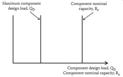
FIG. 1 Deterministic design approach.
2. Current Design Practices
2.1 Deterministic Design Approach
The deterministic design approach, often referred to as the allowable stress design (ASD) approach, is shown schematically in FIG. 1.
The maximum component design load QD, shown in FIG. 1, is generally determined from one of the following load cases:
• Extreme wind
• Extreme ice with concurrent wind
• Broken conductor and/or overhead ground wires
• Construction and maintenance
• Legislated loads
FIG. 2 exemplifies representative load cases for a typical steel lattice tower where different members of the structure are controlled by different load conditions.
===
FIG. 2 Typical steel lattice tower loading-load cases for structural
elements.
NESC heavy (ice and wind) One broken OHGW combined with wind and ice One broken conductor bundle combined with wind and ice Heavy wind, no ice Wind on bare tower (no conductors or OHGW) Vertical load at any conductor support Vertical load at any OHGW support
===
Design load cases used in practice in North America are normally based on the NESC (IEEE, 2006), American Society of Civil Engineers (ASCE) Manual 74 (Wong and Miller, 2010), and/or the Canadian Standards Association (CSA) Standard C22.3 (CEI/IEC, 2006). The NESC divides the United States into three large global loading zones-heavy, medium, and light-and specifies radial ice thickness, wind pressure, and temperature relationships to define the minimum load levels that must be used within each loading zone. In addition, the NESC introduces the concept of safety factor in terms of an overload capacity factor (OCF) to cover uncertainties stemming from the following:
• Likelihood of occurrence of the specified load
• Dispersion of predicted strengths
• Grade of construction
• Deterioration of strength during service life
• Structure function (suspension, dead-end, angle)
Both ASCE Manual 74 and CSA Standard C22.3 include loads associated with a 50 year RP as the basis of design.
Nominal component capacities (Rns) are based on using nominal material strength and deformation properties as needed by the component element design model being used by the designer. Component reliability is established by using the following design equation:
[...]
QD is the maximum component design load Rn is the nominal capacity of the component SF is the factor of safety
Above-grade structure component safety factors are typically established in various design codes.
For foundations, the value of the safety factor adopted by the designer is based on the background and experience of the designer. However, surveys of the practice have shown that safety factors used in practice are quite variable, resulting in a wide variation in the level of reliability and cost for foundations.
2.2 Reliability-Based Design Approach
The RBD approach is founded on the assumption that component design loads are not unique but can vary significant over the life of the component-from relatively low loads (such as everyday wind events) to very high loads (such as extreme wind events). Reliability level is defined as the ability of a line (component) to perform its expected capability. In addition, the nominal strength of each component can vary due to differences in as-built material properties, dimensions, construction techniques, and design models. Thus, in an RBD approach, the variability and uncertainty in loads and component strengths are modeled by probability distribution as shown in FIG. 3.
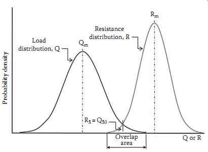
FIG. 3 Combined load and resistance probability distributions.
RBD applied to transmission line design is presented in detail by ASCE and the International Council on Large Electric Systems (CIGRE SC-22, 1995).
Consideration of these uncertainties to achieve a low but acceptable probability of failure is presented in the technical literature on structural reliability. Reliability-based resistance factors, which separate the load (Q) and resistance (R) density functions, are developed for each component element design model so that failure will rarely occur. The probability of Q exceeding R is the probability of failure and is determined by convolution of the Q and R probability functions.
Using advanced first-order reliability methods demonstrated that if the components of a transmission line system were designed for loads associated with a specific time return period (RP) and component capacities have low exclusion limits (e.g., 5%-10%), then the annual probability of failure (Pf ) for these components is approximately equal to
½ ·?RP. For an RP of 50 years, Pf
equals ½ times 50, or a probability of failure of 0.01. In addition, Pf
was shown to be relatively unchanged with respect to the type and coefficient of variations of the Q and R density functions. Thus, the RBD of transmission line elements can be performed using the following equation:
R Effect of Dead Load Q 5 50 = + [ ] ?
( eqn. 2)
where
R5 is the 5% lower exclusion limit (LEL) capacity
? is the load factor used to modify line reliability for return periods higher than 50 years Q50 is the 50 year return period design load event
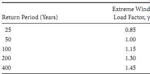
TABLE 1 Approximate Load Factors to Convert "Extreme Wind Loads" from
a 50 Year Event to Other Return Periods-ASCE Manual 74

TABLE 2 Approximate Load Factors to Convert "Extreme Ice with Concurrent
Wind Loads" from a 50 Year Event to Other Return Periods-ASCE Manual
74
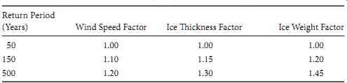
TABLE 3 Default Load Factors for Adjustment of Climatic Loads in Relation
to Return Period vs. 50 Year Event-CSA C22.3 No. 60826
Tables 1 through 3 provide load factor values (?) for extreme wind loads, extreme ice and con current wind loads, and CSA C22.3 No. 60826 (CEI/IEC, 2006) loads, respectively.
The relationship between R5 and Rn is given by the following equation:
R R 5 5 n = F
(eqn .3) where
R5 and Rn are as defined previously F5 is the 5% LEL resistance (strength) factor
Thus the RBD equation is given as follows:
(eqn. 4)
2.3 Security Level
It should be remembered, however, that the failure of every component does not necessarily progress into extensive damage. A comparison of the total risk that would result from the initial failure of components of interest can be accomplished by making a security-level check of the line design. Security level can be described as the ability of a line to restrict progressive damage after the failure of the first component.
Since the OHTL is a contiguous mechanical system, the forces from the overhead conductors and shield wires (wire system) on one side of each tangent structure are balanced and restrained by those on the other side. When a critical component in the wire system fails, energy stored within tensioned elements is released suddenly and sets up unbalanced transients that can cause failure of critical components at the next structure. This can set off a cascading effect that will continue to travel down line until encountering a point in the line strong enough to withstand the unbalance. Unfortunately, a security check of the total line cannot be accomplished from the information describing the single structure in FIG. 2, but perhaps some generalized observations can be drawn for demonstration purposes.
A structure designed for broken conductor bundle and broken shield wire contingencies would not appear to be subjected to a cascade from a broken bare conductor. But what if the conductor was coated with ice at the time? Since ice increases the energy trapped within the conductor prior to release, it might be of interest to determine how much ice would be enough to overcome the contingencies. Modern computer modeling would be employed to simulate ice coating of increasing thickness until the critical amount is defined. A proper micrometeorological study could then identify the probability of occurrence of a storm system capable of delivering that amount of ice at that specific location.
A security-level check can predict the amount of resulting losses and damages that would be expected from an initiating event compared to the other contingencies.
3. Foundation Design
Most often, foundation design is controlled by steady-state and transient loads (one or a combination of both). Construction and maintenance loads must be examined, but rarely influence foundation dimensions. Foundation performance criteria (such as rotation and displacement) result from deterministic evaluations of structure performance needs and can control final foundation size. Failure is not necessarily a catastrophic event, but the point where pre-established movement performance criteria are exceeded.
The IEEE/ASCE Transmission Structure Foundation Design Guide gives a thorough presentation of transmission line foundation design. For either RBD or traditional ASD, the steps involved with transmission line foundation design remain the same:
• Perform subsurface investigation/obtain subsurface information
• Select subsurface foundation geotechnical design parameters
• Select appropriate foundation design model
• Apply loads to design model consistent with RBD or ASB
3.1 Subsurface Investigation
By virtue of their intended purpose, electrical transmission projects traverse large distances across widely varying geologic and geotechnical settings over many miles. Transmission foundation designers must balance cost-effective field investigation with the production of sufficient data for design of foundations that are economical and reliable. An initial qualitative preliminary assessment of subsurface variation should be performed by professionals skilled at geology or geologic engineering to optimize and apportion investigation sites according to the geologic strata. This process includes gathering of prior information in the form of soil reports, geologic maps, aerial photographs, hydrologic reports, etc., combined with new field observations and mapping. A field subsurface investigation based on a thorough review of prior data follows and includes borings, test pits, in situ probes, and geophysical measures. The purpose is to establish one or more idealized profiles of the subsurface and gather samples for laboratory testing.
3.2 Foundation Geotechnical Design Parameters
One of the most difficult aspects of transmission line foundation design is the selection of representative soil/rock design properties for idealized subsurface profiles at each foundation location. The process is generally iterative: the properties are refined as more data are obtained from field in situ work and laboratory testing. Quite commonly, index parameters from standard penetration tests (SPT) and cone penetrometer tests (CPT) are correlated to the design properties as these values tend to be abundant from the investigations. Laboratory testing is used to refine the values along with high-quality in situ methods such as pressure meter testing. Empirical correlations to subsurface properties are extensively used for estimating design parameters. Manuals and guides on this subject have been prepared by the Electric Power Research Institute (EPRI) focusing on the selection of geotechnical design parameters and investigation methods relative to transmission lines. The selection of design parameters must always consider the design model and approach. It is important to understand how models apply soil properties to select reasonable low bound values for use in traditional allowable strength design or to determine nominal values for RBD.
3.3 Foundation Design Models
It is of great importance that the foundation designer selects a model that accurately reflects subsurface conditions and reactions to the applied loads. With the advent of modern computer analysis programs, there is a tendency to use the software at hand and make the design fit the program. Additionally, some utilities require specific models or software be used in their specifications. In any case, the designer needs to fully evaluate foundation models and understand the applications and limits.
Spread footings (cast-in-place concrete, precast concrete, grillages, pressed plates) provide basic resistance to axial forces (uplift and compression), while considering the load orientation (inclination and eccentricity) of the applied loads. Foundations must be designed to prevent shear failure and excess settlement in compression and have adequate size and depth to prevent uplift failure or excessive lift of foundation legs. The IEEE/ASCE foundation design guide offers a number of models for spread footings using traditional design methods. AASHTO LRFD Bridge Design Specifications (AASHTO, 2010, Section 10.6) give detailed design methods for RBD of spread footings. Spread footings are most commonly used with lattice tower structures and as central bearing foundations for guyed lattice tower structures.
Drilled foundations (including reinforced concrete drilled shafts and direct embedment poles) sup port vertical compressive loads through a combination of side shear and end bearing, vertical uplift loads via side shear with foundation weight, and lateral loads with overturning moments using the lateral resistance of soil/rock within the embedded section. These foundations rely on a complex soil-structure interaction where movement mobilizes soil strength, transferring load in a nonuniform manner. With axial loads, this commonly referred to as a "t-z" effect and with lateral loads, a "p-delta" or "p-y" effect.
EPRI has developed software (FADTools) to model electric system drilled shafts and direct embedment foundations. The lateral load program, MFAD, accurately models the rigid nature of short electric sys tem shafts and is calibrated for both traditional strength design and RBD.
Pile foundations transmit axial compressive loads through soft soils to denser underlying soils or rock. Although pile foundations can provide substantial uplift and lateral resistance, these foundations are most often used for lattice towers which have low shear, low moment, and high axial load. Pile capacity determination is thoroughly described in the AASHTO LRFD Bridge Design Specifications (AASHTO, 2010, Section 10.7) for both ASD and RBD approaches.
Anchors offer resistance to upward loads transferred from either steel structure guy cables or the structure itself (tower leg or overturning moment within a shallow foundation). The anchor may be a buried steel plate or concrete slab or may be a grouted bar or cable within a drill hole. Anchorages may be prestressed to limit deformation of the supporting structure. Anchor capacity is usually designed based on the pull-out capacity of either a wedge of soil (dead-man anchor types), the side resistance of anchor rods, grouts, and surrounding soil/rock (grouted anchors), or both. The IEEE/ASCE foundation design guide provides a more in-depth description of anchor types and general design methods. Many manufactured anchor systems provide proprietary design processes to be used with their products.
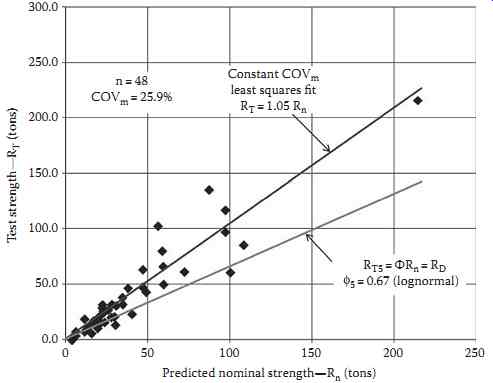
FIG. 4 Cylindrical side shear design model predicted nominal ultimate
uplift capacity, Rn, vs. interpreted test uplift capacity, RT, for drilled
shafts embedded in cohesive soils (D/B = 10).
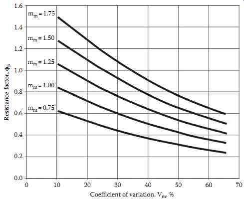
FIG. 5 Relationship between resistance factor, Φ5, and coefficient of
variation, Vm.
3.4 Foundation Reliability-Based Design
The resistance factor, F5 (discussed in Section 2.2), can be determined for a specific foundation design model by using a calibration process. The process involves predicting the ultimate capacities of a given number of full-scale foundation load tests using the design model to be calibrated. FIG. 4 is an example of calibrating the cylindrical shear uplift load design model using 48 full-scale drilled shaft uplift load tests, where each drilled shaft is embedded in a cohesive soil.
The data presented in FIG. 4 show that the cylindrical shear uplift load design model for drilled shafts embedded in cohesive soils has a 5% LEL resistance factor, F5, of 0.67. This resistance factor is computed using the following equation:
F5 m 5 m m 1 k V = - ( )
(eqn. 5)
where mm is the mean of the m-values for each test, wherein each m-value equals test resistance divided by predicted nominal capacity Vm is the coefficient of variation of the m-values As shown in FIG. 4, mm = 1.05 and Vm = 25.9% for the design model.
For a lognormal distribution of m, k5 is given by the following equation:
k 1 1 64 925V 5 m = - 0 0 0 00 . ( . . ),
(eqn. 6) where Vm is in percent.
Substituting with the preceding equations gives
F5 m m m m 1 = - × + × - -
( . . ) 1 64 10 9 25 10 2 5 2 V V (eqn. 7)
FIG. 5 provides plots of F5 vs. Vm for values of mm from 0.75 to 1.75.
The use of statistical data coupled with reliability theory meets the objective of providing a consistent level of safety in design. This approach, however, relies on a sufficient quantity and quality of test data
that, in many cases, is simply not available. When information is insufficient, many agencies and organizations tasked with development of resistance factors calibrate the results by curve-fitting of ASD safety factors. Calibration by fitting to ASD also offers an opportunity to adjust resistance factors developed from reliability theory to insure design results similar to ASD where justified. Monte Carlo simulation has also been used successfully for performing reliability analyses and developing resistance factor.
No matter the method, estimation of foundation resistance factors must involve the use of engineering judgment. Limited or low-quality data should be taken into account in determining RBD methods. Poor or insufficient data can result in overly conservative resistance factors that produce designs in excess of ASD methods, thus discouraging designers in their use. The fact that transmission foundations have historically performed very well with relatively few failures indicates both success in the application of electric system foundation design and the opportunity to provide more economical and reliable designs in the future.