AMAZON multi-meters discounts AMAZON oscilloscope discounts
1. Introduction
High-voltage direct current (HVDC) energy transmission was developed in the late 1920s, and the first commercial HVDC submarine cable started operation in 1954. This system used mercury-arc valves, which required constant maintenance and rebuilding. With the development of the high-voltage and high-power thyristors in the early 1970s, thyristor valves gradually replaced the mercury-arc valves.
Thyristor valves increased system reliability significantly with reduced maintenance. This resulted in fast development of the technology and the building of several new HVDC systems worldwide. Today, HVDC is a mature, well-developed technology.
The thyristor-based HVDC system uses current-commutated converters (valves), because the thyristors cannot be switched off. They switch off naturally at current zero, when the polarity of current changes.
The current source inverter-based system is designed to transfer large amount of power for long distance or bridged long water ways, sea crossing where the AC cable cannot be used because of the large capacitive current. The thyristor converter-based HVDC system is economical for transmission lines longer than 300 miles and transports 300-500 MW power. The typical application of this system is interconnection between two points. The taping of an HVDC line is difficult with thyristor-based converters. Another application is the back-to-back ties, which provides asynchronous interconnection between two AC systems without transmission line. The asynchronous interconnection permits the regulation of power transfer, blocks cascading failures, and prevents the increase of short-circuit current.
The classical HVDC system is based on a well-established and mature technology. TABLE 1 presents the list of most operating HVDC systems together with reliability data. The energy availability of most systems is close to 90%. The energy utilization is very low for some systems because they are mostly used for standby capacity. The utilization of other systems is more than 90%.
The forced energy unavailability is the amount of energy that cannot be transported due to forced outages. The scheduled energy unavailability is the amount of energy that cannot be transported due to scheduled maintenance outage. These data give information about the system maintenance requirements.
[coming soon] TABLE 1 System Energy Availability, Energy Utilization, and Converter Station Energy Unavailability
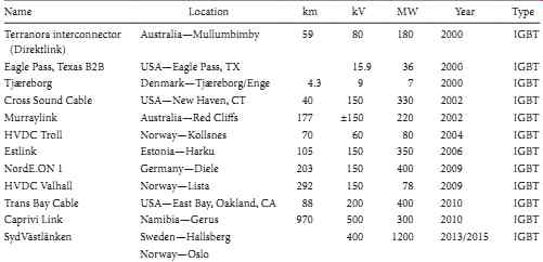
TABLE 2 Light HVDC Systems
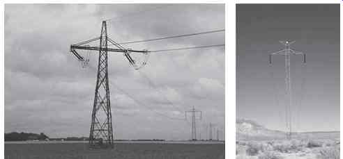
FIG. 1 Examples for HVDC transmission lines. (From Wikipedia: High-voltage
direct current.)
An important reliability index is the number of thyristor failures per year, which is given as a percentage of the total number of thyristors. A typical value is under 0.5%. The data in TABLE 1 prove that classical HVDC is a very reliable system.
The recent development of high-power insulated gate bipolar transistors (IGBT) has caused revolutionary changes in HVDC technology and has made the voltage source converter-based DC transmission system possible. The first system has been built 10 years ago by ASEA Brown Bowery (ABB). Today, few manufacturers like Siemens and Alston also offer this technology, and several systems are successfully in operation.
TABLE 2 shows the list of existing and future HVDC projects using voltage source converters. In addition to the DC links, the voltage source IGBT converter is used for static VAR compensation.
The voltage source-based HVDC system is designed for less power than the classical thyristor-based HVDC system. One of the major advantages is the multiterminal DC or DC network building. Typical applications are as follows:
• Small isolated remote load supply
• Power supply to an island or offshore oil and gas platforms
• Interconnection of asynchronous grids
• Infeed to cities by land cables
• Interconnection of small-scale (low-head hydro) generation
• Connection of offshore wind power generation to power grids
An HVDC transmission line has only two conductors as shown in FIG. 1.
2. Current Source Converter-Based Classical HVDC System
Most classical HVDCs in operation are point-to-point transmission systems where a large amount of energy is transported between two regions. A typical example is the Pacific Intertie that trans ports the energy generated by hydro plants in Oregon and Washington to the Los Angeles area in summer and feeds the surplus energy from Los Angeles to Oregon in winter. These systems use line-commutated current source converters with thyristor valves. The operation of this converter requires synchronous generators or synchronous condensers in the AC network at both ends. The rating of the Pacific Intertie is 3100 MW, ±500 kV with a length of 846 miles. In China the rating of Biswanath-Agra is 3600 MW, ±600 kV.
The HVDC system is expensive because of the need for AC filters, DC filters, and a large iron-core smoothing reactor. Another problem is the reactive power consumption of both DC terminals. A large capacitor bank, a synchronous condenser, or a static VAR compensator is needed. This results in a further increase in the cost.
The current-commutated HVDC system cannot supply power to an AC system which has no local generation. The control of this system is complicated. It also requires fast communication channels between the two stations. FIG. 2 shows the concept of an HVDC system with thyristor valves. The major components of the system are converter transformers, converters with thyristor valves, AC and DC filters, and a smoothing reactor.
The operation records of the more than 30 operating HVDC systems are very good. They are reliable with relatively low maintenance requirements. The first HVDC system between Gotland island and Swedish mainland operates at 150 kV and transports 30 MW power through a 60 mile submarine cable.
This system was commissioned with mercury-arc valves in 1954 and was modernized in 1970.
The HVDC systems can be "monopolar" or "bipolar." FIG. 3 shows the concept of these two arrangements.
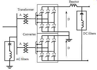
FIG. 2 The concept of an HVDC converter with thyristor valves.
In a monopolar arrangement, the system has only one conductor or cable, and the current returns through the ground or sea. The National Safety Electrical Code prohibits this type of operation for long time because the ground current produces corrosion and may endanger life. The monopolar operation is permitted in case of emergency for limited time only. The monopolar operation is definitely unacceptable in the heavily populated continental United States. However, more than six large HVDC systems operate in this mode worldwide. It is believed that the sea return is acceptable in underdeveloped areas. The obvious advantage of this system is the reduced number of conductors or cables.
The bipolar system has two conductors, and the midpoint of the system is grounded. This eliminates ground currents during normal operation. In case of faults on one cable, the system can operate in monopolar mode for short period of time.
2.1 Description of Classical HVDC
The typical architecture of an HVDC link with thyristor converters is shown in FIG. 4. The link must be supplied both side by an AC system with short-circuit ratio larger than 10, to assure proper operation. The thyristor converter requires reactive power and sinusoidal supply voltage both side.
The thyristor converter-based HVDC cannot supply a network without generation. It is not suitable for black start of an AC system. This type of HVDC line can provide emergency power only if the AC system can generate sinusoidal voltage and provide reactive power.
The system has two terminals interconnected by a DC transmission line. Each terminal has two converters connected in series. The midpoint of the converters is grounded. This is a bipolar system, where the converters generate +VDC and -VDC voltages. The higher voltage at converter 1 drives current through the DC line to converter 2. The current direction is determined by the orientation of the thyristors in the converters. The only possible DC current direction is shown in FIG. 4.
The direction of the power transfer is determined by the voltage direction. The reverse of the power direction requires the reverse of the voltage direction. FIG. 4 shows the case when converter 1 operates as rectifier and converter 2 as inverter. The power follows from converter 1 to converter 2. The upper terminal voltage is positive, and the lower one is negative. The power reversal requires the change of the upper terminal voltage to negative and the lower terminal voltage to positive.
In both cases, the absolute value of the voltage of converter 1 is slightly higher than converter 2 to maintain the current flow from converter 1 to converter 2.
The converter operation generates harmonics in both the AC and DC sides. The harmonics are eliminated by AC and DC filters.
The converters are supplied by Y-Y and Y-delta connected transformers. This generates 30° phase shift between the secondary transformer voltages. The upper converter is supplied by Y-Y transformer, and the lower by Y-delta transformer. The converters are connected in series; consequently, the generated DC voltages are added together. The 30° phase shift eliminates the 3rd-11th harmonics. This system requires only 13th and 15th harmonic filters.
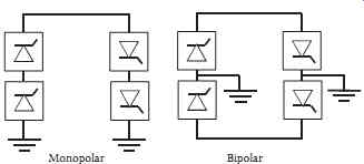
FIG. 3 Monopolar and bipolar arrangements of the HVDC system.
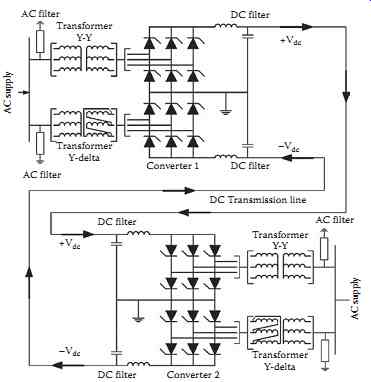
FIG. 4 HVDC transmission system.
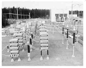
FIG. 5 AC filters on a converter station. (ABB, Raleigh, North Carolina.)
The filters are tuned LC circuits containing inductance and capacitance in series. FIG. 5 shows the filters arranged in a converter station yard. The figure shows the capacitor banks and inductances placed on racks. It can be seen that the space requirements for the filters are significant. The filters occupy close to the same area as the converter building.
The converter transformers can be single-phase units or three-phase transformers. The converter current is built up to square-shape pulses; consequently, the transformer must be designed to tolerate harmonics. FIG. 6 shows single-phase converter transformers built along the converter building. The transformers are outdoor constructions, but placed in front of the building, and the converter site bushing directly penetrates the building through a hole. The transformers are connected to the AC bus and connected in Y-delta and Y-Y.
Each converter contains six thyristor valves as shown in FIG. 4. The thyristor valves are built with a large number of thyristors connected in series as shown in FIG. 7. The high-power thyristor rating is 8-10 kV and 4-5 kA. A 600 kV valve requires over hundred thyristors connected in series. The thyristors are arranged into modules containing 5-10 thyristors connected in series. The water-cooled heat sinks are placed between the thyristors, and an inductance is connected in series with each module.
This inductance reduces the derivative of current change during turn on.
The individual thyristors are protected by parallel connected CR snubber circuits (R, C), which assure equal voltage distribution during turn on and turn off of the thyristors. FIG. 7 shows the concept of a valve module assembly.
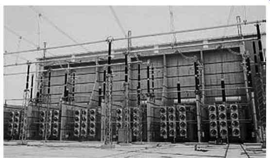
FIG. 6 Single-phase converter transformers. (ABB, Raleigh, North Carolina.)
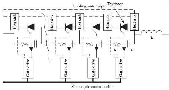
FIG. 7 Thyristor valve module concept.
Four modules with inductance are assembled in a rectangular insulated tray, which is shielded by rounded metal sheets. Ten to twelve series connected trays are assembled to form the valve. The trays or layers are insulated by corrugated epoxy rods. FIG. 8 shows the valves suspended from the ceiling.
The figure also shows the end of the transformer bushings.
The thyristors are fired by direct light firing, or a driving circuit is used to generate the gate pulse.
The driving circuit is controlled by a light signal through fiber-optic links. The driving circuits are powered by the voltage across the snubber circuit. The direct light firing requires very bright powerful light sources. The control of the firing through fiber-optic links requires less-power full-light sources.
FIG. 9 shows a high-power thyristor designed for direct light firing.
The thyristors are liquid cooled with deionized water, which is continuously circulated through a single-circuit cooling system with redundant pumps.
2.2 Operation of the HVDC System
The major building block of the classical HVDC system is the three-phase bridge converter shown in FIG. 10. The converter is supplied by a three-phase voltage source and contains six thyristors. The thyristors are fired in sequence 1-2, 2-3, 3-4, 4-5, 5-6, 6-1. Always two thyristors are conducting simultaneously, one in the top row and the other in the bottom row. The transfer of current from one thyristor to the other is called commutation.

FIG. 8 Valve hall with valves suspended from the ceiling. (ABB, Raleigh,
North Carolina.)
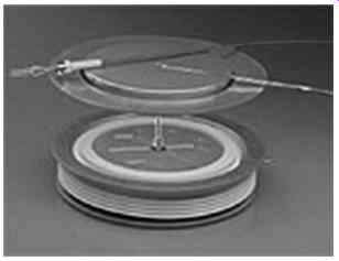
FIG. 9 Direct light-fired thyristor. (Siemens, Charlotte, North Carolina.)
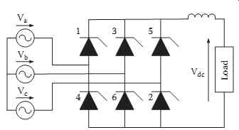
FIG. 10 Simplified bridge converter for operation analysis.
Assuming that the supply inductance is negligible, the firing and follow-up conduction of the two thyristors connects the supply line-to-line voltages to the DC load. Consequently, the DC voltage will be equal with the line-to-line voltages.
Accordingly when thyristors
1-2 conduct Vdc = Vac
2-3 conduct Vdc = Vbc
3-4 conduct Vdc = Vba
4-5 conduct Vdc = Vca
5-6 conduct Vdc = Vcb
6-1 conduct Vdc = Vab
FIG. 11 visualizes the variation of the output DC voltage production.
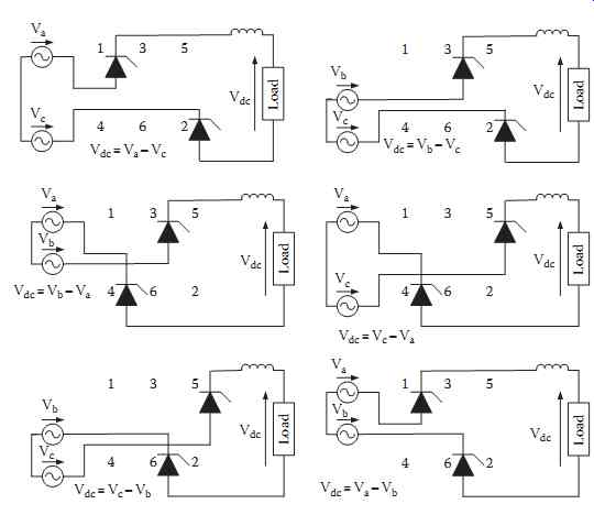
FIG. 11 DC voltage produced by sequential conduction of thyristors.
We also assume that the reactance on the DC side is large, which assures that the DC current is constant. This applies that the thyristor currents are square-shape pulses with 120° duration.
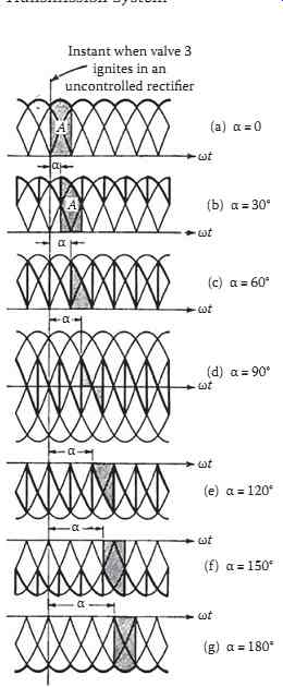
FIG. 12 DC voltage wave shape without overlap. (From Kimbark, E.W., Direct
Current Transmission, vol. 1, Wiley-Interscience, New York, 1971, Technology & Engineering,
508pp, Figure 18.)
In the real life, the supply inductance is not negligible, which results in overlapping during commutation. The overlapping angle is around 10°-15°. In this simplified analysis, we assume zero overlapping angle or instantaneous commutation.
The output DC voltage can be regulated by delaying the firing angle, which cuts out a section of the voltage as shown in FIG. 11.
FIG. 12 shows that the increase of delay angle reduces the average DC voltage. At 90° delay, the DC output voltage is zero, and beyond 90°, the voltage is negative. This implies that in the HVDC system of FIG. 4 when converter 1 works as a rectifier, the typical delay angle is 5°-15°.
Simultaneously, converter 2 works as an inverter. In converter 1, the thyristors are oriented upward, and in converter 2, the thyristors are oriented downward. In converter 2, the thyristors are rotated by 180°, which reverse the output voltage. The inverter voltage must be less than the rectifier voltage to assure current flow. The voltage difference drives the DC current from the rectifier to the inverter. The difference is the voltage drop on the DC line.
This requires that converter 2 operates with a firing angle of 160°-170° delay angles. This produces negative voltage, but because converter 2 conduction direction is reversed, the inverter and rectifier voltage is in the same direction. The inverter typically operates constant firing angle of 165°-170°, and the current flow is controlled by the rectifier.
3. HVDC with Voltage Source Converters
The voltage source converter-based HVDC system is a fast developing technology, which uses IGBT switches and pulse-width modulation (PWM). The capacity of a voltage source converter- based HVDC system is limited to 1200 MW and ±320 kV in 2010. The semiconductor manufacturers increase the capacity of the IGBT switches, and with this, the capacity of the HVDC system is increasing. Presently, ABB and Siemens are selling IGBTs rated 6500 V, 600 A for HVDC systems.
The IGBT has voltage-controlled capacitive gate, and it is shunted by a parallel connected diode in reverse direction.
The first voltage source converter-based HVDC was introduced by ABB in 1997. Presently, more than 16 systems are in successful operation, and few new systems are under construction. However, the technical parameters of the voltage converter-based HVDC system indicate that this technology produces a nearly ideal transmission component that has the potential to change the conventional methods of electric power transmission and distribution. The market survey shows that ABB offers the HVDC light, Siemens the HVDC Plus system and ALSTON prepares a demonstration site with voltage source converter.
3.1 Description of HVDC with Voltage Source Converter
The basic module of the voltage source converter is the three-phase bridge built with insulated gate bipolar transistor (IGBT), shunted by diodes in the reverse direction. FIG. 13 shows basic circuit diagram of the voltage source converter.
The system supplying the converter must not have high short-circuit capacity or at the receiving end not need to have generation. The converter can supply an island without generation. It has black start capacity. Typically a standard transformer and a series converter reactor (inductance) connect the converter to the network. Because of the PWM system, only small AC filter is needed.
At the DC side, two capacitors, connected in series, serve as a filter. The midpoint of the capacitors is grounded.
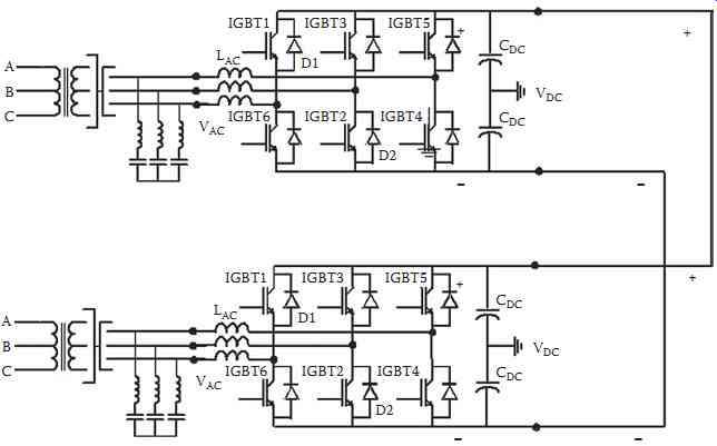
FIG. 13 HVDC system with voltage source converter.

FIG. 14 StakPak module of IGBTs. (ABB, Raleigh, North Carolina.)
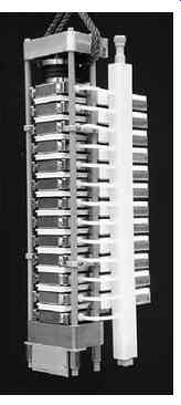
FIG. 15 IGBT valve used for Light HVDC. (ABB, Raleigh, North Carolina.)
The converters can operate automatically without communication between the stations. The system can regulate both the amplitude and phase angle of the AC voltage. This means the independent regulation of the active and reactive power. The direction of power transfer depends on the voltage. The current flows from the converter operating higher voltage than the other. The reversal of the power flow requires the reversal of current direction and not the reversal on the voltage. The system is suitable for multiterminal operation.
Each valve consists of several hundred IGBT connected in series. The valve is divided into series connected modules called by ABB StakPak. FIG. 14 shows the StakPak which can have up to 30 IGBTs connected in series. The IGBTs are cooled by deionized water. The even voltage distribution is assured by a parallel connected voltage divider.
The voltage across each IGBT is rectified and provides power for the gate drive of the IGBT. An optical link from the ground controls the gate drive of the IGBTs. FIG. 15 shows a section of an IGBT valve used for Light HVDC systems.
Siemens introduced the HVDC Plus system and built few projects. The major contribution is the development of a new type of multilevel converter. FIG. 16b shows the basic circuit, which contains two IGBTs and a capacitor. Several of these units are connected in series to form the valve as shown in FIG. 16b. The converter produced voltage wave shown in FIG. 16c.
The HVDC with voltage source converters is built indoor except the transformers. The station is built with modular equipment, in which the components are installed in enclosures in the factory.
FIG. 17 shows the photograph of a Light HVDC substation.
FIG. 17 shows four transformers (one spare) and filters. The converters are in the building. In the foreground of the buildings are the cooling equipment. The fans are visible on the picture.
The Light HVDC system can supply transmission lines or cables. The advancement of cable technology promotes the use of land cables, which can be competitive with the overhead lines in difficult terrains.
The HVDC Light uses extruded polymer cables for land cable use and also for submarine cable use.
The HVDC Light is an ungrounded bipolar system with a positive and a negative cable. As an overhead line, it needs also two conductors (positive and a negative). FIG. 18 shows typical polymer cable pair designed for the HVDC Light application.
The cable has aluminum conductors surrounded by a black semiconduction layer, which reduces the electrical field on the conductor surface. The white extruded polymer is the main insulation of the cable.
The polymer insulation is surrounded by black semiconducting layer and a grounded woven copper shield conductor. The next white layer prevents water penetration. The outer jacket of the cable is PVC.
FIG. 19 shows the construction of a typical submarine cable. The coaxial single-conductor cable is XLPE insulated. It can be seen that the construction of this cable is more ragged than the cables used on land. This 400 kV 1000 A cable has two layers of shield conductors.
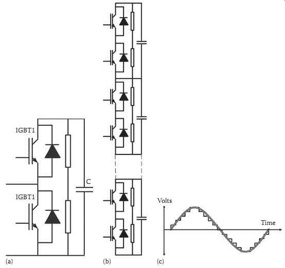
FIG. 16 Multilevel converter. (a) Basic module, (b) generated wave-form,
and (c) series connected modules form the valve.
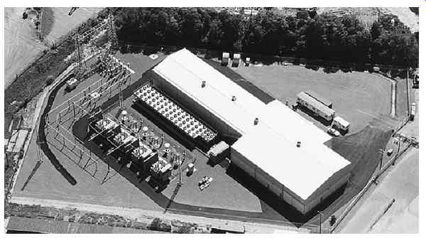
FIG. 17 Light HVDC station. (ABB, Raleigh, North Carolina.)
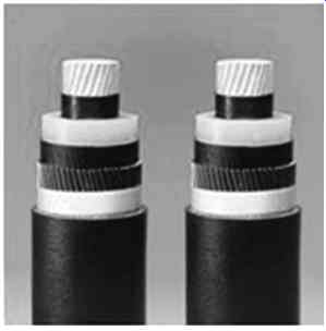
FIG. 18 Pair of extruded polymer HVDC cables. (ABB, Raleigh, North Carolina.)
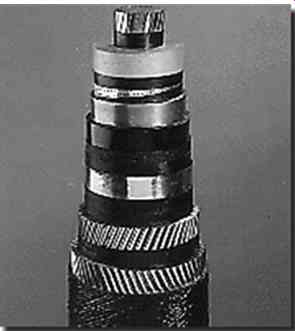
FIG. 19 DC submarine cable, 500 MW, 400 kV, and 1250 A.
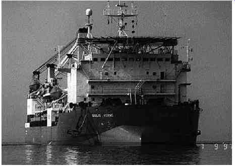
FIG. 20 Giulio Verne cable laying ship. (Siemens.)
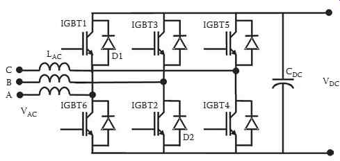
FIG. 21 Circuit diagram of a PWM converter.
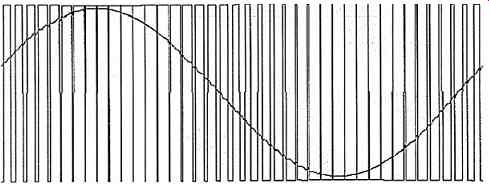
FIG. 22 PWM voltage waveform.
Submarine cable installation requires a cable ship ( FIG. 20). Pirelli operates the Giulio Verne cable ship, which is capable of laying cables in all weather conditions. The ship is equipped with a 7000 ton rotating turntable.
3.2 PWM Technology
The modern manufacturing industry requires AC motor drives that are accurately regulated. These drives should operate close to unity power factor and not generate significant current harmonics in the AC supply. These requirements led to the development of the PWM technique. FIG. 21 shows the concept of PWM, and FIG. 22 presents the generated voltage waveform.
The converter in FIG. 21 can operate as a rectifier or as an inverter. It is built with six semiconductor switches, which are shunted by diodes. The semiconductor switch can be a transistor, IGBT, or a MOSFET. The six switches form a six-pulse bridge. A capacitor shunts the DC side, and three inductors are connected in series with each phase on the AC side. The switches are turned on in sequence, e.g., 12, 34, 56, etc. The turn on of switch 1 connects the positive DC terminals to phase A, and the turn on of switch 2 connects the negative DC terminals to phase B. The switches are turned on for a short period of time, which generates a pulse train at the AC terminals.
FIG. 22 shows the generated pulse train. It can be seen that the width of the pulses is modulated and hence the name PWM. The filtering of the output voltage produces a sinusoidal waveform.
The generation of the PWM waveform is illustrated in FIG. 23. As shown in FIG. 23a, a high-frequency triangular wave is compared with a 60 Hz reference sine wave to generate the control pulses shown in FIG. 23b. The intersection of the triangular "carrier" and the sinusoidal "reference" determines the pulse width as demonstrated in FIG. 23. If the sinusoidal reference voltage is higher than the triangular carrier wave, the upper semiconductor switch (1, 3, or 5) connects the phase terminal to the positive DC terminal ( FIG. 23a); if it is lower, the bottom switch (2, 4, or 6) connects the phase terminal to the negative DC terminal ( FIG. 23b).
The frequency spectrum of the generated pulse train contains the base 60 Hz component and other high-frequency components. The latter are multiples of the triangular carrier frequency. The AC inductance blocks the current harmonics at the AC side, which are further reduced by a high-pass filter.
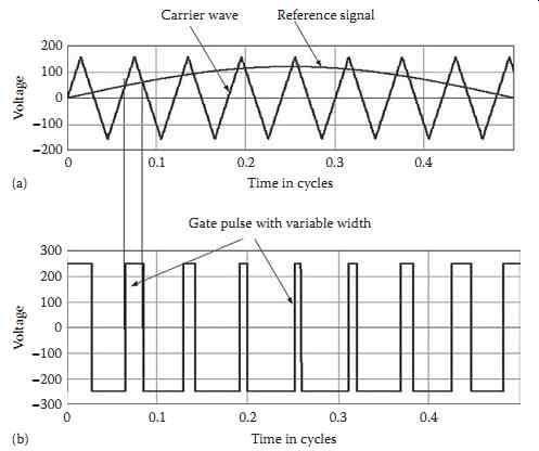
FIG. 23 Generation of PWM voltage waveform. (a) Control and reference
signal for PWM gate pulse generation, and (b) PWM gate pulse.
The DC capacitor reduces the harmonics at the DC side. The DC capacitor also controls the turn-off overvoltages, generated by the switches, by providing a low-impedance path. The output voltage can be controlled by the pulse pattern and by the DC voltage.
This converter can supply a passive AC system. It can be used to start an AC system after a fault. If the AC system has a voltage source, controlling the converter voltage phase angle can independently regulate the real and reactive power transfer. The active power depends mostly on the converter voltage phase angle, and the reactive power is dependent on the voltage magnitude.
The converter can act as a motor or generator without mass and can provide either capacitive or inductive reactive power. The converter controls the AC and consequently does not contribute to the AC short-circuit current.
The PWM converter is an ideal device for energy transmission. It was proposed and developed more than a decade ago for low-power applications. The lack of high-power high-frequency switches has pre vented application to HVDC.
For start up, the AC breaker is closed at one side. The diodes in the converter produce a DC voltage and energize the DC line. This charges the power supplies of the gate drive units that permits a start of the converter operation. The first converter that starts will control the DC voltage. The second converter that starts controls the power transfer. The reactive power is controlled independently at each station.
The active power flowing in the DC network has to be equal to the active power transmitted from the first network to the second network plus the losses. In this system, one converter station maintains the DC voltage constant. The other station controls the active power flow within the limits of the system.
This is achieved by controlling the phase angle between the network voltage and the sinusoidal reference control voltage.
If an AC fault occurs at the side that receives the power, the power-controlling converter is blocked. This interrupts the outgoing power, but not the incoming power. This results in a fast rise of DC voltage. The DC voltage-controlling converter will reduce or even reverse the incoming power to maintain the DC voltage level.
If the fault occurs on the AC side of the converter that controls the DC voltage, the converter is blocked, and a sudden drop in the DC voltage occurs. In this case, the remaining converter will control the DC voltage and simultaneously control its reactive power flow. The operation mode of this converter will be similar to the operation of a dynamic voltage restorer.
In case of a ground fault in the AC system, the converter control will reduce the DC voltage to limit the current flow to the prefault value. The voltage source converter will not increase the short-circuit current in the AC system.
Voltage source converters, applied to HVDC, can permit multiterminal operation. Several converters can be connected in parallel to a DC transmission line. As an example, a planned four-terminal circuit is shown in FIG. 24.
One possible operation mode is that the Hydro generator maintains the DC voltage constant. This is achieved by modulation of the PWM pattern. The DC voltage is measured and compared with the reference DC voltage. The difference signal changes the amplitude or phase angle of the reference sine wave. With this control method, the Takatz Hydro maintains the power balance by keeping the DC voltage constant.
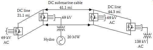
FIG. 24 Example for a planned multiterminal DC system.