AMAZON multi-meters discounts AMAZON oscilloscope discounts
1. Introduction
Since the days of Nikola Tesla and Thomas Edison, electrical transmission and distribution (T&D) engineers have evaluated the merits of various bare overhead conductors. Copper was employed early on, due to its excellent conductivity. Soon, however, usage trended toward aluminum, due to its lighter weight and lower cost. These advantages overcame the roughly 40% lower conductivity of aluminum compared to copper. Another factor was that copper was considered a strategic material in high demand during World War I.
As long-distance transmission applications emerged, it was clear that line construction economics could be optimized with longer spans, and the strength of aluminum was insufficient. This deficiency was remedied in two ways-either using stronger aluminum alloy conductors (AAC) or supporting outer aluminum strands with a steel core. For more than 100 years, composite conductors made of aluminum for good conductivity and steel for high strength have been the first choice of T&D engineers. In many cases, the venerable aluminum conductor steel reinforced (ACSR) conductor is still the optimal economic choice. Its place as an industry standard has been secure for over 100 years.
Higher conductor operating temperatures offer an opportunity to reduce the initial cost of a transmission line, at the expense of higher resistive losses, especially when the line loading is high.
Nowadays, many utility companies are using a short time horizon in assessing total lifetime cost of construction and operations, and are focused on cutting the initial capital cost. ACSR operating temperatures have generally been limited to 93°C-100°C; otherwise annealing of the aluminum strands will cause the conductor to lose a significant portion of its initial strength and render it unable to meet the design requirements.
To add flexibility in conductor choices, manufacturers began offering aluminum conductor steel sup ported (ACSS), with the aluminum fully annealed, so there was full reliance on the steel for strength.
This new composition allowed a typical maximum operating temperature of 200°C. A key weakness of this product is that the thermal coefficient of expansion of steel is high, and taller structures are required to meet clearance requirements at maximum sag. Starting with the decade of the 1990s, a trend emerged in which this "high-temperature high-sag high-loss" conductor was and continues to be widely used in new construction.
The demand for electrical energy continues to increase, either through new residential, commercial, and industrial development, or through new electrically powered devices at existing locations. The need for electrical transmission capability also increases as generation sources are added, and the mix of generation changes, as is evidenced in the recent trend toward renewable resources. Transmission planners are often faced with a choice between adding new lines and increasing the capacity of existing ones.
Expanding the throughput in a given corridor is sometimes the only choice available, especially in a fully developed urban setting.
Power line ratings are generally limited by the thermal capability of the conductor, or by clearance to the ground, other wires, or nearby structures. Increased capacity can be obtained by installing an additional conductor per phase, or by re-conductoring with a higher-capacity conductor. However, when expanding the number of conductors in a bundle, structure strength will likely be insufficient unless the upgrade was envisioned in the original design. When replacing an ACSR conductor with ACSS, the maximum sag is significantly greater, and clearance is normally an issue. As a result, the cost of these options can be exorbitant since most or all of the existing poles or towers may have to be replaced.
Even when the benefits yield a good value proposition, it may be impossible to find a construction window in which the outage of the existing facility is acceptable.
These considerations led to the search for high-temperature low-sag (HTLS) conductors that can pro vide a sizeable rating increase, when a direct replacement occurs, with HTLS wire substituted for AAC or ACSR (CIGRE 2009). Several products have been launched to fill this need. The list includes the following:
• Aluminum conductor composite core (ACCC)
• Aluminum conductor composite reinforced (ACCR)
• Gap-type ACSR conductor (GTACSR)
• INVAR-supported conductor
While conductors with a conventional steel core are still the predominant players in the marketplace, the HTLS offerings have established a toehold and have been a valuable addition to the engineers' menu of choices. For example, over 2000 circuit miles of ACCC have been installed. Engineers should be familiar with the options, the pros and cons of each, and special situations that are most likely to call for a high-capacity specialty conductor.
2. General Considerations
T&D conductors are generally composed of multiple layers of wire strands for flexibility. When trying to achieve a high ampacity, one of the possibilities is to specify trapezoidal shaped strands. For a given overall conductor diameter, this adds weight but significantly increases conductivity and reduces ohmic resistance to electrical current flow. "Trap wire" is available in any conductor type. However, most ACSR and ACSS are still sold with round strands, because the cost of strand shaping exceeds the expense to beef up the structures to accommodate the added loading due to wind on a larger diameter wire.
Some of the materials used in HTLS conductors come at a cost premium. An example is the added expense of using a high-temperature annealed aluminum alloy. There is a compensation, however; designing lines with HTLS conductors will open the possibility of using longer spans or shorter structures.
The nomenclature used for an HTLS conductor of a given outside diameter has sometimes been selected to match the names used for standard ACSR or ACSS conductors. A common conductor size such as Drake may also exist in ACCC or ACCR. Of course, this is only a shorthand way to refer to relative size, and the specific characteristics of the conductor will govern the design.
It is not certain that any conductor would survive a direct hit from a high-powered rifle. However, the brittleness of ACCR makes it a particular concern, and galvanic corrosion could occur after damage to the outer fiberglass strands of the ACCC core. Even rare events should receive due consideration of the probability and repercussions. Gunfire damage testing at Western Area Power Administration evaluated five conductor types: AAC, ACSR, ACSS, ACCC, and ACCR. A 12-gauge shotgun (3.5 in. magnum shell with #2 steel shot) caused only superficial damage. In additional testing, conductors were tensioned to 6000 lb, and a 30-06 caliber hunting rifle (180 grain bullet with ballistic tip) was fired directly at the core of each conductor type. No conductor fared well. Convention steel core ACSR was destroyed, and loss of tension was 100%. The 30-06 rifle test caused total core failures in ACCC and ACCR also.
===
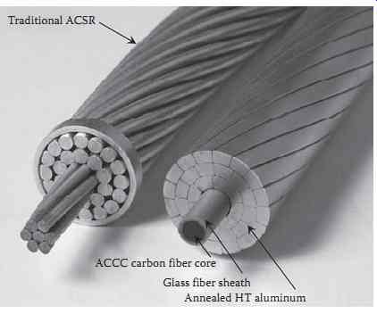
FIG. 1 ACCC conductor. (CTC Cable Corporation, Irvine, CA.)
Traditional ACSR ACCC carbon fiber core Glass fiber sheath
Annealed HT aluminum
===
3. Aluminum Conductor Composite Core
Development of ACCC began in the early 2000s. It consists of a hybrid carbon and glass fiber composite core which utilizes a high-temperature epoxy resin matrix to bind thousands of individual fibers into a unified load-bearing tensile member. The central carbon fiber core is surrounded by high-grade glass fibers to improve flexibility and toughness, and prevent galvanic corrosion. The composite core exhibits a high strength to weight ratio and has a very low coefficient of thermal expansion which reduces conductor sag under high electrical load/high-temperature conditions. The composite core is surrounded by aluminum strands to carry electrical current. The conductive strands are generally trapezoidal in shape to provide the greatest conductivity and lowest electrical resistance for any given conductor diameter ( FIG. 1).
The maximum recommended conductor temperature is given as 180°C for continuous operation, and 200°C for a short-term emergency. One design element used to allow operation at high temperatures is the use of fully annealed Type 1350-0 aluminum. For an EHV application, where lower conductor temperature operation is assured, non-annealed alloys are appropriate and can be used to increase the overall conductor strength.
The ratio and type of carbon and glass fibers used in standard ACCC core provide a tensile strength of 320 KSI and a modulus of elasticity of 16 MSI. Strength and modulus are design variables that can be optimized to a particular set of requirements, such as a long span or a heavy ice or wind region. Thus, the choices include ultralow sag and ultrahigh strength. A twisted pair variation is also being offered.
ACCC was originally developed as a reconductoring option, typically to replace ACSR. Several of the ACCC conductor designs were created to match an ACSR counterpart. As an example, Drake ACCC/ TW has the same outside diameter and approximately the same weight as Drake ACSR. The lighter core is offset by additional aluminum. In Europe, ACCC designs were introduced in mm2 sizes and given city names. Standards for the general category of polymer matrix composite conductors (PMCC) are being developed by ASTM and IEC, and will help users in understanding and selecting conductors such as ACCC.
Applications for ACCC have primarily been geared to upgrading the capacity of existing lines.
However, some of the attributes of ACCC are cited as reasons for consideration in other circumstances.
These include the following:
• Very high strength designs with good self-damping, for long spans
• Better elasticity, for lower probability of failure in a heavy ice load condition
• Corrosion resistance
One concern about ACCC is that it may be susceptible to breakage during installation. Strict attention must be paid to guidance from the manufacturer regarding the diameter of sheaves (pulleys), pulling tensions, and rate of change of the tension. If too much tension is applied around a tight radius, or if tension is applied in a sudden jerky fashion, the core can be damaged. There have been numerous successful installations where construction crews stayed within the pulling guides. There have also been a few instances where the wire broke because crews failed to comply with the instructions.
Other concerns expressed about ACCC include how stable the organic compounds are at high temperature, and whether there might be a failure mechanism similar to brittle fracture in polymer com posite insulators. As noted earlier, there is an extensive body of research, as well as about a decade of field experience, to draw upon when evaluating if and how to apply a PMCC.
4. Aluminum Conductor Composite Reinforced
Published articles on ACCR technology date back to the mid-1990s. The core of ACCR gets its strength from tens of thousands of strands of an advanced material-a ceramic aluminum oxide fiber. These strands are embedded in an aluminum matrix, so the resulting core wire has the look and feel of a common metal. While the core wires have strength and stiffness comparable to steel, they have much higher conductivity and lower weight. As with other commercial HTLS conductors, in order to allow elevated operating temperatures, the current carrying strands are made of an aluminum-zirconium alloy.
ACCR can carry twice the current of the same size conventional ACSR ( TABLE 1). Its core has a coefficient of thermal expansion that is roughly half that of steel, and its strength to weight ratio is better than double ( FIG. 2).
The team that developed this technology was headed by a manufacturer with a large research staff and expertise in high-tech materials. It also included independent scientists, a conductor manufacturer with stranding experience, producers of different styles of line hardware for dead ends and suspensions, test laboratories, and host utilities with facilities that served as test beds. The team also received encouragement from the U.S. Department of Energy, because the DOE concluded it was in the national interest to accelerate field testing and deployment, to ensure that the technology could be used in upgrading electric transmission infrastructure in the United States.
The industry/DOE team conducted rigorous laboratory and field tests. These covered material proper ties, conductor tests, and accessory tests. Evaluations of the conductor covered tensile strength, stress-strain behavior, electrical resistance, axial impact strength, torsional ductility, short-circuit behavior, crush resistance, lightning resistance, and so on.
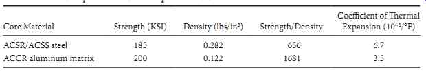
TABLE 1 Comparison of Core Properties: ACCR vs. Steel FIG. 2 ACCR conductor.
(3M Corporation, Maplewood, MN.)
The first 230 kV installation took place on a Western Area Power Administration line near Fargo, North Dakota, in 2003. That locale is subject to extreme weather conditions, including low temperatures, ice, and high wind speeds. Testing was also conducted at the opposite end of the spectrum, in metro Phoenix, Arizona. ACCR was installed to deliver the entire output of a Salt River Project generating unit. The high load factor and extreme desert southwest heat created an interesting test environment.
The tests included both compression and formed wire-type accessories, as well as vibration dampers.
Advantages touted for ACCR include being well suited for long-span crossings, regions with heavy ice loads, and installations in corrosive environments.
In general, installation techniques are similar to those for ACSR, AAC, or ACSS. However, despite the ACCR core wires being similar in appearance to aluminum, they are quite brittle and will snap if bent to a tight radius. Early on, the manufacturer conducted extensive tests and developed guidelines for pulling tension and diameter of sheaves and bull wheels. Because installations have been carefully supervised, and crews have followed the guidelines, no conductor damage during installation has occurred to date.
5. Gap-Type ACSR Conductor
This conductor has a strikingly different geometrical configuration than ACSR. It is made up of heat resistant aluminum strands surrounding a steel core. The outer aluminum layer(s) can be made of either round or trapezoidal strands. However, the furthest inside layer of aluminum must be comprised of trapezoidal strands, configured to form a gap between the steel core and the aluminum layers.
====
FIG. 3 Gap-type conductor.
Round aluminum strands Trapezoidal aluminum strands Gap filled with high temperature grease
Steel core
===
The gap can be filled with a grease that is resistant to high temperatures. Among other advantages, this arrangement of wires enhances the conductor's ability to self-dampen aeolian vibration ( FIG. 3).
When GTACSR is installed, all of the tension is applied to the steel core. The aluminum layers hang loosely. As a result, at temperatures higher than at stringing, all of the mechanical strength is sup plied by the steel. At lower temperatures, sag performance is similar to conventional ACSR. Installing GTACSR is considerably more complex than standard conductor.
As an application example (Zamora et al. 2001), in Spain, an existing line was limited by clearance at an operating temperature of about 50°C. ACSS and INVAR conductors had similar performance to ACSR in the temperature range below 50°C and were not able to significantly increase the line capacity.
However, assuming that GTACSR was installed at 20°C, the flatter sag-temperature characteristic above that temperature allowed for a significant benefit and increased the maximum temperature to 80°C.
6. INVAR-Supported Conductor
The key to reduced conductor sag with the INVAR approach is the use of an iron-nickel alloy for the core wires. This specialty alloy includes about 36%-38% nickel, and it has a very favorable coefficient of thermal expansion. For a given increase in temperature, INVAR's elongation is approximately one-third that of steel. The low-sag core is paired with specially formulated aluminum conductor strands, which are alloyed with zirconium to allow a continuous operating temperature up to 210°C. The core wires can be galvanized (zinc-coated) or aluminum-clad in areas where there is a particular concern about corrosion.
At low temperatures, some of the INVAR conductor's mechanical strength comes from the aluminum alloy current carrying strands, and in that mode, the sag-temperature characteristic is similar to ACSR. Above a transition temperature in the range of 85°C-100°C, all of the mechanical strength is provided by the INVAR core. Thus, in the higher-temperature range, the sag-temperature relationship is very flat.
INVAR conductors have the advantage of being similar to the familiar ACSR: metallic, ductile, and unquestioned longevity. There are no special precautions required during installation. As with other HTLS conductors, it can be used as a direct replacement for ACSR, yielding a twofold increase in line capacity without replacing any poles or towers.
Another similarity in benefits with other HTLS wires is that ecological or environmental benefits can result, since a right-of-way can transmit the same power with fewer or shorter structures, and fewer wires. Many stakeholders feel that the ultimate plus for the environment is to avoid building new lines at all, and meet transmission capacity needs by uprating existing lines. Substantial cost savings are possible when new right-of-way acquisition is avoided and tower modifications are not required.
7. Testing: The Sequential Mechanical Test
In view of the novel make-up of the advanced conductors that are available in the marketplace, certain companies have pressed for more exhaustive tests than have traditionally been conducted on conventional conductors. An example of this is the sequential mechanical test proposed by Eric Engdahl and Bruce Freimark of American Electric Power. The purpose of this test is to simulate the multiple mechanical challenges that a conductor experiences over its installed life. Rather than performing various independent tests, in this case, the same conductor is subjected to a series of stresses, one after the other.
The sequential mechanical test consists of the following:
• Sheave test
• Aeolian vibration test
• Galloping test
• Load cycling test
• Tensile test to failure
The test protocol includes demanding requirements in each of the five segments of the evaluation. The criteria for success consist of no visible damage during the first four tests, and withstanding at least 100% of rated breaking strength (RBS) before failure in the tensile test. The following paragraphs describe the ACCR test in particular.
In the sheave test, a 125 ft length of the conductor is subjected to various tensions and break-over angles, to simulate forces that would occur during line construction. Some adjustments in the setup are allowed, in order to comply with manufacturer recommendations and standard practices. When testing a particular size of ACCR (1033 kcmil TW-T13), the elements of this test were the following:
• Twenty passes around a 28 in. sheave with a break-over angle of 10°, at 20% RBS tension.
• Seven passes over the 28 in. sheave with a break-over angle of 20°, at 20% RBS tension.
• Finally, three passes with a break-over angle of 30°, at 20% RBS tension. Per a normal field approach for ACCR, this step was conducted with an array of seven 7 in. roller, with an effective bending radius of 60 in.
The test setup consisted of a triangular loop. In addition to the test sheave, there were a 55 in. drive sheave and a 55 in. idle sheave at the other corners. Tension was applied using a hydraulic cylinder attached to the test sheave. The break-over angle was adjusted by inserting appropriate length wire rope slings, connected using Kellum grips. Line tensions were determined using a dynamometer in the test loop and a load cell between the test sheave and the hydraulic cylinder. With this setup, the conductor actually experienced two passes around 55 in. sheaves for every pass over the test sheave.
The setup for the aeolian vibration test calls for an active span that is about 65% of the overall span.
This ensures that vibration activity in the back span is less than in the test span. About 80 ft of conductor is stretched between dead ends and tensioned to 20% RBS. A formed wire-type suspension assembly separated the active and back spans, and a shaker was positioned about 9 ft from the dead end of the active span. The test was conducted for 100,000,000 cycles, at a frequency of slightly over 30 Hz and an amplitude of one-half conductor diameter.
To prepare for the galloping test, the aeolian vibration test setup was adjusted, with the back span being increased to the same length as the test span. A galloper was positioned about 5 ft from one dead end. Conductor tension was set around 4% of RBS, and the test was conducted for 100,000 cycles, at a frequency of 1.88 Hz and a peak-to-peak amplitude of 26 in. (1/25 of the span length). Another detail of the test setup was that guides were used to ensure that the conductor movement was all vertical, with no horizontal component.
Once the sheave, aeolian vibration, and galloping tests were completed, and no visible damage was observed in a careful examination of the conductor (particularly focusing on the wire under the suspension assembly, where damage was most likely to have occurred), setup for a load cycling test commenced. The test sample consisted of the approximately 10 ft length of conductor under the suspension, plus an additional 5 ft on either end, for a total length of 20 ft. The wire was gripped by a compression dead end at one end and a resin socket at the other, and instrumentation was provided for direct strain measurement during the test.
The load cycling sequence consisted of increasing tensions, with a load hold of varying lengths:
• 10%, 20%, 30%, 40%, 50%, 60%, and 70% RBS-5 min hold
• 85% RBS-30 min hold
• Decrease tension back to 10% RBS This was repeated for four cycles. On the fifth cycle, the hold at 85% RBS was extended to 3 hours.
To prepare for the final tensile test to failure, the sample from the load cycling test was cut in half and fitted with a resin socket on each end, to ensure even loading of each conductor strand. The sample was loaded until it failed in tension, with the loading steadily increased at a rate of 1% strain per minute. In the case of the ACCR test, the sample failed at 109% of the RBS.
For more details of sequential mechanical test results, see references by Engdahl et al. (2009) for ACCC and McCullough (2009) for ACCR.
8. Conclusion
Research and development activity in the last decade has culminated in new choices. The list of T&D conductors in the marketplace has expanded. Particularly when there is a system need for added throughput in an existing corridor, the new HTLS conductors can be viable economic choices. Each product has unique advantages and concerns. It is important to make an informed decision when considering
• ACCC
• ACCR
• GTACSR
• INVAR-supported conductor Whether the requirement is a capacity upgrade, a long span river crossing, or a region subject to heavy ice loading, HTLS conductor may be the preferred choice.