AMAZON multi-meters discounts AMAZON oscilloscope discounts
6. Voltage Source Converter-Based Topologies
The alternative to thyristor-based compensators, in either a shunt configuration (SVC) or a series con figuration (TCSC), is to make use of synchronous voltage source controllers based on voltage source converter topologies. These converters employ force-commutated switching devices, with turn-on and turn-off capabilities, rather than thyristors, which can only be turned on. Force-commutated devices are derived either from the thyristor technology, the gate turn-off thyristor (GTO), and the improved switch, the integrated gate-commutated thyristors (IGCT), or from transistor technologies. The more common and universally used switch today is the insulated gate bipolar transistor (IGBT).
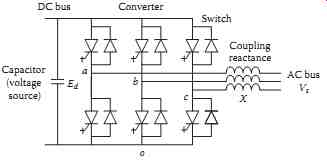
FIG. 11 Basic structure of a two-level self-commutated voltage source
converter.
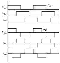
FIG. 12 AC voltage waveforms of a self-commutated inverter with fundamental
frequency gating and a constant DC bus voltage.
6.1 Basic Structure of a Synchronous Voltage Source
Force-commutated switches allow the implementation of self-commutated converters, which can generate an arbitrary waveform. They do not need to be connected and synchronized to an AC source to operate, as is the case with thyristor-based converters. Thyristor converters require an AC grid voltage to commutate or turn off the thyristors.
In self-commutated converters, the switching of the devices on a DC bus, defined by means of a capacitor, can be done in such a way as to produce a synthetic AC voltage at the AC terminal of the converter of an arbitrary shape, with an amplitude, frequency, and phase that are set by the converter gating and control system. When producing a sinusoidal AC voltage source and synchronized to the AC grid, these converters become synchronous voltage sources.
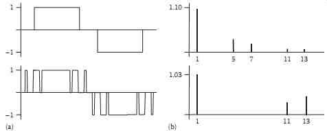
FIG. 13 AC voltage and harmonic content of a self-commutated converter.
(a) Waveforms for single pulse patterns and pulse width modulation (SHE)
patterns (fifth and seventh harmonic elimination). (b) Harmonic spectrum
for single pulse patterns and pulse width modulation (SHE) patterns.
The basic topology for the voltage source converter is the six-switch full-bridge topology, most commonly used in many low and medium power applications, but also in high power applications ( FIG. 11). A square wave can be produced by switching the devices appropriately once per AC cycle. It has a fully controllable fundamental amplitude, frequency, and phase ( FIG. 12). The amplitude is dictated by the magnitude of the DC bus voltage, the frequency by a clock, and the phase by the position of the gating signal with respect to an AC reference waveform (the AC grid in compensators).
The output voltage consists of a fundamental voltage component, and low-order harmonics of frequency (6n ± 1) and amplitude 1/n, where n varies from 1 to infinity. The dominant harmonics for a three-phase waveform using fundamental switching frequency gating are the 5th, 7th, 11th, and 13th harmonics ( FIG. 13).
Harmonics can be reduced or eliminated using any one of the following methods or combinations of methods:
• Harmonic filters: These typically are passive LC tuned filters or low pass LC filters.
• Phase shifting transformers: By connecting n converters in series, for example, and feeding them with voltages that are phase shifted 60°/n, lower-order harmonics can be eliminated. For two converters fed from transformer secondary voltages shifted by 30°, the harmonics of order 5 and 7 are eliminated, leaving the 11th and 13th as the dominant harmonics.
• Pulse width modulation (PWM) techniques: The principle consists of introducing notches in the output AC voltage, such that a number of harmonic components are eliminated (or reduced) in the output waveform. There are a number of such techniques available. At low switching frequencies, the selective harmonic elimination (SHE) approach is used ( FIG. 13). At higher switching frequencies, techniques based on a carrier, such as a triangular carrier (Sine PWM), or on computations, such as space vector modulation techniques, naturally eliminate low-frequency harmonic components in the AC voltage.
• Multi-level and multi-module structures: Multiple levels can be created in the output voltage of a converter by using a number of topologies; the better known is the diode clamped capacitor multi-level inverter, usually in a three-level configuration. An alternative is to connect a number of basic converter modules in series, such as the two-level converter, appropriately phase shifted to eliminate a given number of harmonics at the combined output of the converter.
• Modular multi-level structures: In high-voltage and high-power applications, the use of a large number of low voltage devices in series is required to obtain the required AC output voltage magnitude. This is the case with any line-connected high-voltage compensator. Switching devices can then be configured in modules, each capable of a controlled low voltage output. A large number of these modules are then connected in series and gated appropriately to achieve a stepped AC waveform. With a large number of steps, an output voltage waveform that is close to sinusoidal is synthesized. This practically eliminates the need of filtering the AC waveform.
The amplitude of the output AC voltage is controlled either by varying the amplitude of the DC bus voltage or by using a PWM technique. The latter technique is preferred. There are a number of such techniques available. At low switching frequencies, the SHE approach is used ( FIG. 13), where the amplitude of the fundamental component of the voltage is one of the harmonic components controlled.
At higher switching frequencies, techniques based on a carrier, such as a triangular carrier (Sine PWM), or on computations, such as space vector modulation techniques, can be used.
The frequency and phase of the AC voltage are synchronized with the AC grid by means of a phase-locked loop (PLL) for example, when the converter is connected to the electric grid and used as a compensator.
The phase of the AC voltage is set by the phase relation between the switch gating signals and the AC grid.
When connected to an AC grid, a coupling inductance must be provided, since the converter, being a matrix of switches, is essentially a voltage source ( FIG. 11). This inductance can be provided by the coupling transformer and/or by an appropriately sized inductor.
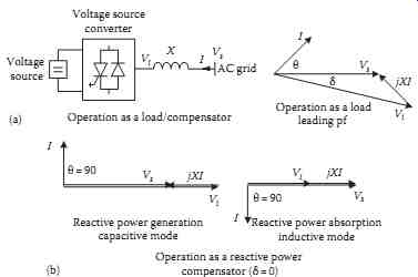
FIG. 14 Operation of a synchronous voltage source. (a) Equivalent circuit
(per phase) and phasor diagram-general case. (b) Operation
as an SVC.
6.2 Operation of Synchronous Voltage Sources
When connected to the AC grid, and assuming the general case of a power source on the DC side, the angle d between the AC supply Vs and the fundamental component of the converter AC output voltage Vi can be set to any desired value ( FIG. 14). This angle defines the amount of power flowing between the converter DC bus and the AC supply. This power is controlled by the phase shift between the AC supply and the gating pattern of the converter AC voltage, and by its amplitude. The converter is reversible and the power transfer, neglecting losses, is given by the equation dictating the exchange of power between two synchronous AC sources:
… where X is the coupling reactance and voltages are expressed on a per-phase basis.
In addition, the converter can be operated at a leading or lagging power factor. The reactive power is given by …
Operation is possible in all four quadrants of the Q-P plane ( FIG. 15). However, this requires that energy sources or storage devices be connected to the DC bus to supply or absorb real power. The more common storage devices in power systems are electric storage batteries and superconducting magnet energy storage (SMES) devices. This gives additional flexibility to the compensator in supporting the electric grid voltage.
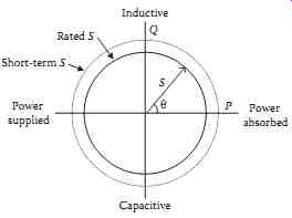
FIG. 15 Power diagram of a self-commutated AC/DC converter with power
factor control and constant AC rms current operation.
FIG. 16 Static compensator (STATCOM)-operating characteristics.
The basic synchronous voltage source discussed previously can be connected to the grid in a shunt configuration. This is the basic structure of a static compensator (STATCOM). The same synchronous source can also be connected in series with the AC grid through a series transformer. It then implements a static synchronous series compensator (SSSC). Finally, because of the presence of the DC bus, a shunt and a series unit can share the same DC bus. The shunt-series structure is known as the unified power flow controller (UPFC).
It should be noted that most of the structures using synchronous voltage sources and presented next can be applied to, and have found applications, in transmission as well as distribution systems.
6.3 Static Compensator
A static compensator (STATCOM) provides variable reactive power from lagging to leading ( FIG. 16), but with no inductors or capacitors required for var generation, as demonstrated in the preceding section. Reactive power generation is achieved by regulating the terminal voltage of the converter. If the terminal voltage Vi of the voltage source converter is higher than the AC bus voltage, the STATCOM produces leading reactive power, that is, it operates as a capacitor. If Vi is lower than the bus voltage, it produces lagging reactive power ( FIG. 14). No net energy is required in this operation, other than supplying the losses associated with the STATCOM operation and with the DC bus capacitor.
The reactive power generated or absorbed by the STATCOM is not a function of the size of the capacitor on the DC bus of the converter, which only sets the value of the DC bus voltage. The capacitor voltage is regulated by the load angle between the converter voltage and the AC grid voltage, as per Equation 4.
The capacitor is rated to limit only the ripple current, and hence the harmonics in the output voltage.
Unlike the SVC, the reactive current or power that can be injected into the AC grid does not depend upon the AC voltage, since the reactive power is not produced by means of capacitors and inductors, but by a synthetic voltage source defined by the DC bus. So long as the DC capacitor remains charged to its rated value, the compensator can deliver its rated current. Because of this feature, the STATCOM is capable of supplying rated currents down to low AC grid voltages. It is also capable of producing cur rents that are larger than rated, with short-term overload values and durations dependent on the design of the converter switches and cooling system.
The performance of the STATCOM is similar to that of a synchronous condenser (unloaded synchronous motor with varying excitation). However, the dynamic response is faster than that of a synchronous condenser and of an SVC, if switched at a frequency higher than fundamental frequency, as with PWM, for example. A STATCOM is more effective than an SVC for arc furnace flicker control because of its dynamic range.
The first demonstration STATCOM of ±100 Mvar rating was installed at the Tennessee Valley Authority's Sullivan substation in 1994 ( FIG. 17). To extend the range of the STATCOM in the capacitive region (with the inductive limit dictated by the STATCOM to 100 Mvar), mechanically switched capacitor banks are added. The control system ( FIG. 18) is similar to that of the typical SVC, with slope control as required. The controller also incorporates a reactive current inner loop and a synchronizing block (PLL).
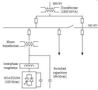
FIG. 17 STATCOM configuration and associated equipment-TVA ( United States).
The advantage of using the STATCOM in this installation has been the fast and coordinated response that it enables, particularly under contingencies. This has allowed deferral of the construction of an additional line or the use of a second transformer bank, resulting in significant cost savings.
STATCOM devices with storage have been successfully implemented, mostly at the distribution level and using the following storage devices: (a) battery storage on the DC bus, to achieve better ride-through and voltage regulation for critical loads in the case of faults and momentary loss of mains; (b) SMES, for applications in transmission and distribution, to support the system voltage in the case of faults on the system; recovery from faults has been found to be faster with the real power injection capability provided by the use of the stored energy.
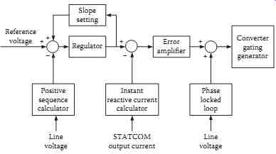
FIG. 18 STATCOM control system configuration-TVA ( United States).

FIG. 19 Static synchronous series compensator (SSSC)-characteristics.
6.4 Static Series Synchronous Compensator
The converter used in a STATCOM can also be used in the SSSC. This device is coupled to the AC grid by means of a series transformer ( FIG. 19), in place of a shunt transformer. It injects a voltage in quadrature with the AC line current, either leading or lagging, rather than injecting a controlled amount of leading or lagging reactive current, as in a STATCOM.
Since the equivalent reactance is the ratio of injected voltage over the line current, the SSSC can be used to emulate a variable inductor or capacitor in series with the line. As a variable series capacitor, it can be used in place of TCSC, with a more controllable characteristic and a faster dynamic response.
6.5 Unified Power Flow Controller
The DC bus of a STATCOM and of an SSSC can be connected together ( FIG. 20) to produce a device named the UPFC. It can exhibit the characteristics of both the STATCOM with shunt current injection, and the SSSC with series voltage injection, with added features. The device has 3 degrees of freedom, control of the reactive powers on the shunt and series connections, and of real power flowing through the common DC bus. This in turn allows real power injection on the shunt and series connections. The DC bus voltage is usually regulated from the shunt side, in a manner similar to a STATCOM.
Power injection on the shunt and series connections increases the flexibility and the number of modes of operation of the UPFC ( FIG. 20). In particular, the STATCOM and the SSSC can be operated the same way as the basic device, and if desired, with the added features provided such as real power injection. Among these are (a) the operation of the series side as a phase shifter, with real power being provided by the DC bus through the shunt side; (b) the operation as a variable line resistance injection (positive or negative), modifying the apparent resistance of the line and therefore the line X/R ratio; this is made possible by injecting real power on the series transformer, the power being provided by the shunt side.
The UPFC has been implemented and tested in an NYPA substation ( FIG. 21) in the form of a convertible static compensator (CSC). Since the converters in the STATCOM and the SSSC have the same rating and configuration, it is possible to have two independent converters, each with its own DC bus, to produce, among others, the following combinations: (1) one STATCOM of a power equal to that of two converters operating in parallel; (2) one SSSC of a power equal to that of two converters operating in parallel; (3) one STATCOM and one SSSC, each of a rating equal to that of one converter; (4) the coupled operation of the STATCOM and SSSC to form a UPFC; or (5) the coupled operation of two SSSCs on separate lines to form an interline power flow controller (IPFC), allowing the interchange of power between the two lines.
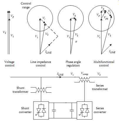
FIG. 20 Unified power flow controller (UPFC)-operating modes.
The potential benefits include (a) improving the voltage support and control; (b) increasing the power transfer capability through the substation; (c) relieving power transfer bottlenecks; (d) maximizing utilization of the transmission system; and (e) reducing power losses on the lines.
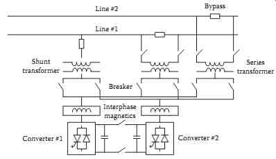
FIG. 21 Convertible static compensator (CSC)-UPFC structure-NYPA (United
States).
7. Defining Terms
Shunt capacitor bank: A large number of capacitor units connected in series and parallel arrangement to make up the required voltage and current rating, and connected between the high-voltage line and ground, between line and neutral, or between line and line.
Voltage flicker: Commonly known as "flicker" and "lamp flicker" is a rapid and frequent fluctuation of supply voltage that causes lamps to flicker. Lamp flicker can be annoying, and some loads are sensitive to these frequent voltage fluctuations.
Subsynchronous resonance: Per IEEE, SSR is an electric power system condition where the electric network exchanges energy with a turbine generator at one or more of the natural frequencies of the combined system below the synchronous frequency of the system.
Also see...