AMAZON multi-meters discounts AMAZON oscilloscope discounts
GOALS:
• list several factors to be considered when selecting and installing electric motor control equipment.
• explain the purpose of a contactor.
• describe the basic operation of a contactor and relay.
• list the steps in the operation of a control circuit using start and stop pushbuttons.
• interpret simple automatic control diagrams.
• draw a simple magnetic control circuit.
Motor control was a simple problem when motors were used to drive a common line shaft to which several machines were connected. In this arrangement, it was necessary to start and stop only a few times daily.
With individual drives, however, the motor is an integral part of the machine, and the motor controller must be designed to meet the needs of the machine to which it is connected.
As a result, the modern motor controller may not just start, stop, and control the speed of a motor. The controller may also be required to sense a number of conditions, including changes in temperature, open circuits, current limitations, overload, smoke density, level of liquids, or the position of devices. Manual control is limited to pressing a button to start or stop the entire sequence of operations at the machine or from a remote location.
The electrician must know the symbols and terms used in automatic control diagrams to be able to wire, install, troubleshoot, and maintain automatic control equipment.
CLASSIFICATION OF AUTOMATIC CONTROLLERS
Purpose
Factors to be considered when selecting motor controllers include the required types of starting, stopping, reversing, running, and controlling speed and sequence. Other factors that influence the selection of a controller include the electrical service, environmental conditions, and electrical codes and standards.
Operation
The motor may be controlled directly or manually by an operator using a switch or a drum controller. Remote control uses contactors, relays, pushbuttons, sensors, and possibly electronics.
CONTACTORS
Contactors, or relays (FIG. 1 and FIG. 2), are required in automatic controls to transmit varying conditions in one circuit in order to influence the operation of other devices in the same or another electrical circuit. Relays have been designed to respond to one or more of the following conditions:
voltage current--current direction power direction phase angle phase failure overvoltage overcurrent differential current volt-amperes power factor impedance temperature undervoltage undercurrent power (watts) frequency phase rotation speed
Magnetic switches are widely used in controllers because they can be used with remote control and are economical and safe.
A relay or contactor usually has a coil that can be energized to close or open contacts in an electrical circuit. The coil and contacts of a relay are represented by symbols on the circuit diagram or schematic of a controller. Symbols commonly used to represent contactor elements are shown in FIG. 3.
If the control coil is connected in series in the motor power circuit, the heavy line symbol shown at the left of FIG. 3 is used. If the coil is connected in parallel (shunt), the light line symbol is used.
A series coil has a large current-carrying conductor with few turns designed to carry large currents. A shunt coil has a small wire size with many turns; it carries small currents. It is possible for a series coil and a shunt coil to have the same ampere turns, producing similar magnetic results.
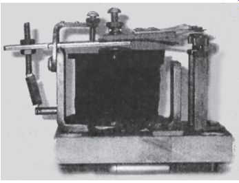
FIG. 1 DC magnetic relay.
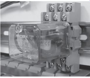
FIG. 2 DC operated relay.
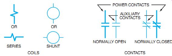
FIG. 3 Schematic symbols for contactor elements.
Contacts that are open when the coil is de-energized are known as normally open contacts and are indicated by two short parallel lines. Contacts that are closed when the coil is de-energized are called normally closed contacts and are indicated by a slanted line drawn across the parallel lines.
To minimize heavy arcing that burns the contacts, a DC contactor usually is equipped with a blowout coil and an arc chute. FIG. 4 shows a magnetic contactor that is provided with a blowout coil and an arc chute.
As the contacts move apart, an arc is established between the contact points. The arc is still conducting current and acts like a conductor. If a conductor is placed in a magnetic field, it tries to move out of the magnetic field (motor action). FIG. 5(A) shows that the current is still flowing through the magnetic blowout coil to the arc. This current in the blowout coil creates a magnetic field as long as there is current in the arc.
The magnetic field deflects the arc away from the contact surfaces, elongates the arc, and "blows" it into the arc chute to be extinguished. As soon as the arc is stretched far enough and broken into small segments, the current flow is interrupted and the blowout coil has no more current and no magnetic effect. FIG. 5(B) shows a contact without blowout coils. In this case, the arc is allowed to stretch and rise through thermal action. As it rises, it is elongated and finally breaks apart at the tip of the arc horns rather than burning the contact closure surface.
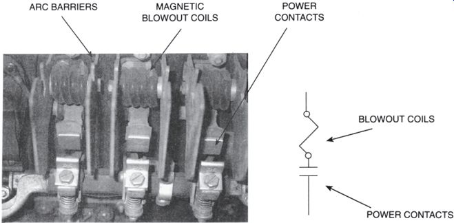
FIG. 4 Magnetic blowout coils magnetically move the arc away from the
contacts.
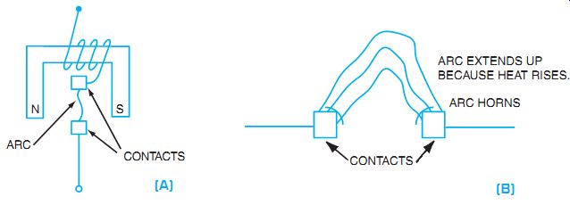
FIG. 5 (A) Magnetic blowout coils are used for arc control on large power
contacts. (B) Contacts without blowout coils rely on the arc stretching to
break.
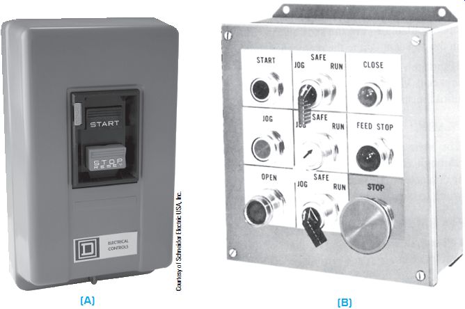
FIG. 6 Pushbutton stations.
PUSHBUTTONS
Pushbutton stations (FIG. 6) are spring-controlled switches, which, when pushed, are used to complete motor or motor control circuits. FIG. 6(B) shows multiple control stations with pushbuttons, selector switches, and pilot indicating lights. Note the "mushroom" stop but ton for easy emergency access. This is often referred to as an E-stop, short for "emergency stop."
The symbols used in schematic drawings to represent momentary pushbutton contacts are provided in FIG. 7. Contacts can either be normally open or normally closed. This is the normal condition when there is no mechanical actuation of the contacts. In the pushbuttons shown in FIG. 7, the contacts are referred to as momentary contacts. This simply means that the contacts change from their normal condition to the opposite condition momentarily when mechanical actuation is applied, and then change back to the normal condition when the actuator is removed. Some contacts are designated as maintained contacts. This means that the contacts stay as activated (held mechanically) until returned to their original position.
NORMALLY OPEN NORMALLY CLOSED OPEN AND CLOSED
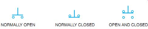
FIG. 7 Symbols for pushbutton contacts.
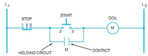
FIG. 8 A control circuit with start and stop buttons and holding circuit.
TYPICAL CONTROL CIRCUIT
FIG. 8 shows an elementary control circuit with momentary start and stop buttons and a sealing, or "holding," circuit. The typical control circuit uses an electromagnetic coil to move sets of contacts. The contacts move to open and close the power circuit to the motor and also to open and close contacts in the control circuit. The control contacts provide a holding circuit in parallel to the start momentary contacts. This parallel circuit is referred to as the sealing circuit or holding circuit. It seals a current path around the normally open start button contacts. The circuit operation is as follows:
1. When the start button is pressed to close contacts 2-3, current flows from L1 through normally closed contacts 1-2 of the stop button, through the closed contacts 2-3 of the start button, and through coil M to line L2.
2. The current in coil M causes the contact M to close. Thus, the holding circuit around contacts 2-3 of the start button closes. The start button may now be released, and even though the spring of the pushbutton opens contacts 2-3, coil M remains energized and holds contacts M closed to maintain a holding circuit around the normally open contacts 2-3 of the start button. Coil M, being energized, also closes M contacts in the power circuit to the motor (not shown).
3. If the stop button is momentarily pressed, the circuit is interrupted at contacts 1-2, and coil M is de-energized. Contacts M then open, and coil M cannot be re- energized until the start button again closes contacts 2-3.
SCADA AND HMI
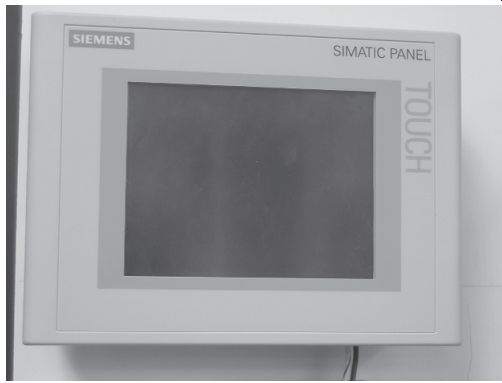
FIG. 9 Human machine interface (HMI) screen to interact with control systems.
SCADA, or supervisory control and data acquisition, also sometimes known as supervisory calculation and data analysis, is a system that uses input and output data from real-world processes and machinery interfaces. These data that are sent to the processors, usually through a programmable logic controller (PLC), are used to monitor, control, and affect the output of the PLC to determine control operations. The PLC operates to control the output functions with predetermined programs and therefore monitors and controls the assigned process. In order for humans to interact with the processor, some method of communication is needed.
Typically this interface to the PLC started out as a program panel, but more recently a personal computer has been used. The personal computer is still used to design and develop the operating program, but the monitoring and changes to the operations can be processed through the human machine interface (HMI). The HMI, as seen in FIG. 9, is a real-time interface to the data acquisition system and a control point so the human operators can change operations based on their decisions.
Often the data are acquired over networks to provide the inputs to the SCADA system. If terminals are used for the interface, they are often referred to as remote terminal units (RTUs). In most cases, SCADA systems run without human intervention as automatic controls or monitoring systems for automatic systems, and the RTU is used for reference and control only if needed. In the event that more human control is desired or needed, the current trend is to use HMIs as interfaces to the control system. The HMI can be connected to the RTU or the PLC to take data and display them in different format.
An HMI can be a control panel with hard button interfaces to change operations of the PLC and therefore the process. The buttons may have multiple functions depending on which program the human operator chooses. The current trend is to make the control buttons as virtual controls that are programmable and can respond to the touch screen of the HMI inter face. In this case, the operations are displayed as graphical elements and the controls can be programmed to respond when people simply touch the screen at the point where they want to make a change or analyze the process. See FIG. 10.
SCADA systems, RTUs, and HMIs have become more reliable and more dependable.
Some automatic safety systems and emergency stop systems have been approved as SCADA systems without the need for redundant hardwired systems. The SCADA and HMIs are typically linked to a historical data system that allows the operators to see data trends and failure modes and track maintenance requirements as a result of equipment wear or sensor breakdown.
The manufacturing and materials-handling industries can predict maintenance with great certainty and help with failure analysis based on the SCADA systems.
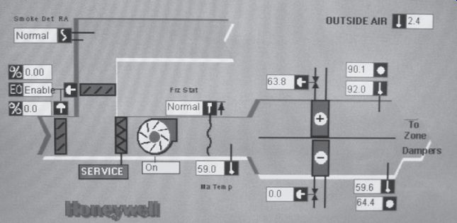
FIG. 10 Sample display screen to show data collection and real-time controls.
SCADA connections and RTUs and HMIs are increasingly being connected through systems that use an open protocol. This means that each individual manufacturer no longer has a specific protocol base that allows only specific compatible hardware to be connected. This was done in the past to force end users to buy from a specific supplier if they wanted the systems to "talk" to each other. Current systems allow competitors to connect to each other's systems, thereby allowing the end users to pick the most effective system to meet their needs. The perceived drawback of open protocol may be that more people can tie into the networks and wreak havoc with critical processes either on purpose or by accident. The fact that major systems such as power plant control or water treatment facilities control could become vulnerable to malicious intent is of concern.
SUMMARY
The basic automatic control circuit is used to control larger motors through electromagnetic relays. This allows the operation to be remotely located and the contactor to be located near the motor. The basic principle uses a momentary-contact switch to close a circuit to a magnetically operated relay.
QUIZ
Select the correct answer for each of the following statements, and place the corresponding letter in the space provided.
1. Early motor installations consisted of
a. individual drives.
b. a common line shaft drive.
c. automatically controlled motor drives.
d. remotely controlled motors.
2. Individual motor drives require
a. single-phase motors.
b. automatic controllers.
c. speed rheostats.
d. gear heads.
3. Automatic DC motor controllers are designed to respond to in temperature, open circuits, current limitations, and _
a. wire size.
b. fuse rating.
c. speed acceleration.
d. brush assembly.
4. Interpretation of automatic control circuits requires the recognition of ___
a. color.
b. electrical circuit symbols.
c. ratings.
d. parallel circuits.
5. A relay symbol shows the ___
a. number of turns in a coil.
b. relay current rating.
c. relative position of the component parts.
d. size of the contacts.
6. A relay is classified as a piece of electrical equipment at least one__
a. coil.
b. resistor.
c. coil operating one contact.
d. coil operating two contacts.
7. Normally open contacts are __
a. open at all times.
b. open when the relay coil is de-energized.
c. open when the relay coil is energized.
d. contacts that open a circuit.
8. Normally closed relay contacts are represented by the symbol:____
a. c.
b. d.
9. A holding circuit bypasses ___
a. the armature circuit.
b. the field circuit.
c. the "on" pushbutton contacts.
d. the relay coil.
10. Schematic control diagrams are read from _____
a. top to bottom.
b. bottom to top.
c. right to left.
d. field to armature circuit.