AMAZON multi-meters discounts AMAZON oscilloscope discounts
GOALS:
• explain how relays operate.
• list the principal uses of relays.
• describe different relay control and load conditions.
• tell how SCRs operate.
• identify relay component symbols.
• connect different relays in a circuit.
• identify and use various timers.
• use proper timer symbols in schematic diagrams.
RELAYS
Relays are devices used to relay or multiply control signals or electrical contact closures. The relay concept is used where a small voltage at low current operates a set of electrical contacts to an open or closed position. This contact operation in turn controls a larger electric load as it relays the electrical operations.
Another common use of a relay is to multiply a single signal to open or close multiple contacts to control multiple electrical loads.
ELECTROMECHANICAL RELAYS
Electromechanical relays, contactors, and motor starters basically operate by the same principles. These electrically operated switches respond to the electromagnetic attraction of an energized coil of wire mounted on an iron core. The devices differ in the amount of current that each associated contact must switch. The relay-which can be compared to an amplifier-is usually used to switch small amounts of currents (usually 0-15 amperes) in many control circuits (FIG. 1). Uses of relays include switching (on and off) larger coils of motor starters, contactors, solenoids, heating elements, and small motors. Other uses are alarm systems and pilot light control. Relays have many industrial and commercial applications, both AC and DC.
A small current flow and/or low voltage applied to a relay coil can result in a much larger current or voltage being switched. One input signal (voltage) may control several output (switched) circuits (FIG. 2).
The coil voltage of the relay is separate or different from those at the switched contacts; this is called separate control. However, the coil voltage may be the same system voltage as the switched voltage.
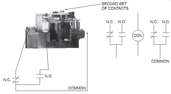
FIG. 1 Control relay and associated coil contact diagram.
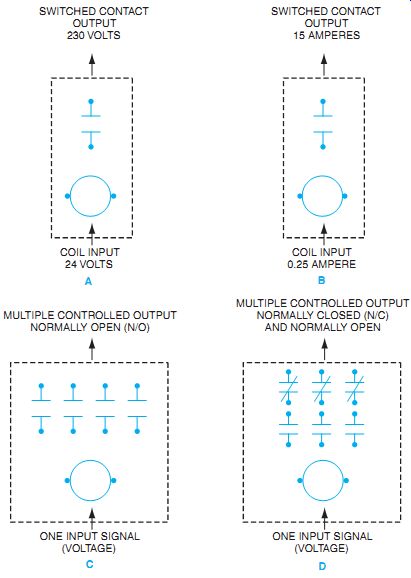
FIG. 2 Several electrical-mechanical relay uses and contact configurations.
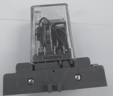
FIG. 3 "Ice-cube" relays and plug-in bases for easy replacement.
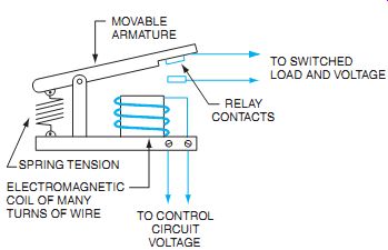
FIG. 4 Construction of a typical electromagnetic control relay.
Relays are available in many shapes and sizes. Some are sealed in dustproof, transparent plastic enclosures, shown in FIG. 3. The general construction of a typical relay is shown in FIG. 4.
Note in FIG. 2 that relay contacts may be normally closed or normally open. The action of the contacts is to switch something "on" or "off " depending on the configuration.
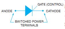
FIG. 5 Schematic symbol for an SCR, which is the heart of the solid state
relay.
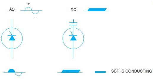
FIG. 6 An SCR contacts current in the forward direction until the voltage
is reduced to zero.
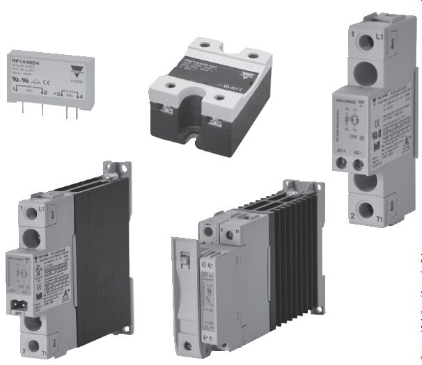
FIG. 7 Typical package for SSRs.
SOLID-STATE RELAY (SSR)
A solid-state relay (SSR) can be used to control most of the circuits that the electromechanical relay controls. By comparison, the SSR has no coil or contacts. The semiconductor industry has developed solid-state components with unusual applications to the industrial control processes.
These components are compact, versatile, and very reliable if used in the proper application.
The silicon-controlled rectifier (SCR) is probably the most popular solid-state device for controlling large and small electrical power loads. Basically, the SCR either conducts or does not conduct an electric current. When it is not conducting, the SCR offers almost a complete blockage to the current. It passes only a few milliamperes to the load. For this reason, some manufacturers place contacts from electrically operated contactors in the total circuit to disconnect the load completely.
The SCR will not conduct when the voltage across it is in the reverse direction. It conducts only in the forward direction when the proper signal (voltage) is applied to the gate terminal (FIG. 5). Once it is conducting, the SCR cannot be turned off immediately. It is necessary only to provide a small signal to start the SCR conducting a current. It continues to conduct even without a signal from that point on, as long as the current is in the forward direction. The only way to stop the SCR from conducting is to reduce the current flow below the holding cur rent level or disconnect it from the system. On AC, of course, this happens every half cycle, so this characteristic is no problem (FIG. 6). For DC applications, the voltage is reduced to zero by interrupting the circuit, generally with a contact on an electromagnetic relay.
FIG. 7 shows a typical SSR. Note the input and switched output terminal connections. FIG. 8 shows these connections completed. Terminal wiring is very simple and consists of two input control wires and two output load wires. The connecting terminals are clearly identified on SSRs (as they are on electromechanical relays). The relay in FIG. 8 has a light-emitting diode (LED) connected to the input or control voltage. When the input voltage turns the LED on, a photodetector connected to the gate of the TRIAC turns the TRIAC on and connects the load to the line. This optical coupling is commonly used with SSRs. These relays are referred to as being optoisolated. This means that the load side of the relay is optically isolated from the control side of the relay. The control medium is a light beam. No voltage spikes or electrical noise produced on the load side of the relay is therefore transmitted to the control side.
SSRs have a wide range of input or control voltage designs. The SSRs may operate at TTL (transistor-transistor logic) levels plus 5 volts DC. They may operate at levels between 3 and 30 volts DC or other relays at between 90 and 120 volts AC. Considerations as to what style of relay include the way that the SSRs turn on.
SSRs are available with a design to match the requirements of the application. An SSR with zero switching capability is used for resistive, inductive, and capacitive loads. Zero switching refers to when the SSR's output is activated. When the control signal voltage is applied, the SSR output turns on at the first zero crossing of the line voltage; therefore, the response time is typically less than a half cycle. These are the most commonly used SSRs.
Analog switching is used for resistive loads. The input control can be varied from 4 to 20 milliamps (mA). This SSR can then perform phase control when the output is controlled by adjusting the input voltage and controlling the "on" time of the load. These SSRs can be used to reduce inrush currents or to control heating elements for precise heat requirements.
Analog full-cycle switching is also used for resistive loads. This SSR responds to 4-20 mA or 1-10 volts DC control values. A low value of input control turns on the output and leaves it on for a specific number of output cycles. A high value of input turns on the output for a full
"on" state of the load. These relays are used for analog control of heating elements with varying input values. Instant on switching is used for inductive loads. The SSR is immediately and fully "on" after application of the control voltage. The output turns on anywhere during the cycle, and the response time is typically less than 1 millisecond. This relay is used to control solenoids or coils where immediate response is needed. Peak switching is used for heavy industrial loads such as transformer loads. The output will turn on at the first AC peak value after application of the control voltage. The last switching state is a DC switching SSR. The application of a DC input turns on the DC voltage output. The relay is used for controlling DC loads. When this relay is used for coil loads, such as DC motors and coils, then an inductive-kick protection diode is needed to prevent damage to the relay when the load is switched off.
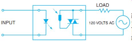
FIG. 8 SSR used to control an AC load.
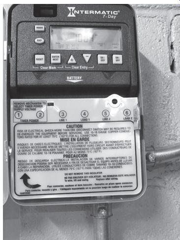
FIG. 9 Synchronous clock timer.
TIMERS
Timers come in many styles and with different operating characteristics. Mechanical timers use either clock motors to operate a mechanical trip mechanism or solenoids to create timing operations. Pneumatic timers use air, a diaphragm, and an operating solenoid to cause a time delay.
FIG. 9 shows a mechanical time-clock type of timer. This type of timer is used for rough time-of-day timing to turn lights or equipment on or off at an approximate time of day. Tabs on the face of the clock are moved to create different on and off periods.
Pneumatic timers such as that in FIG. 10 were typically used for "on" or "off " delay operations. The symbols shown in FIG. 11 depict the type of timer operation and the operation of the contacts. In on-delay timers (time delay on energization, TDE), the contacts stay in their original position until a solenoid plunger has moved through its entire travel distance.
The travel time is controlled by adjusting a needle valve to allow the air to escape in front of the solenoid diaphragm. The timer solenoid has power applied to pull the plunger into its timed-out position. The contacts can start as either normally open or normally closed and will change to the opposite position at the end of the time, if power is still applied to the solenoid coil.
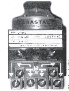
FIG. 10 Mechanical timer uses air (pneumatic) timing.
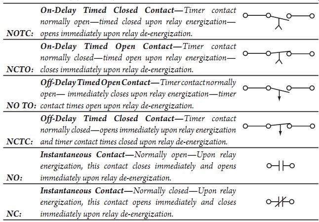
------ FIG. 11 Schematic symbols and explanations for various timing
possibilities.
TIMING SYMBOLS
NOTC:
On-Delay Timed Closed Contact-Timer contact
normally open-timed closed upon relay energization- opens immediately upon relay de-energization.
NCTO:
On-Delay Timed Open Contact-Timer contact
normally closed-timed open upon relay energization- closes immediately upon relay de-energization.
NO TO:
Off-Delay Timed Open Contact-Timer contact normally open- immediately closes upon relay energization-timer contact times open upon relay de-energization.
NCTC:
Off-Delay Timed Closed Contact-Timer contact
normally closed-opens immediately upon relay energization and timer contact times closed upon relay de-energization.
NO:
Instantaneous Contact-Normally open-Upon relay
energization, this contact closes immediately and opens
immediately upon relay de-energization.
NC:
Instantaneous Contact-Normally closed-Upon relay energization, this contact opens immediately and closes immediately upon relay de-energization.
----------------------
The off-delay timer (time delay on de-energization, TDD) acts in the opposite mode. In other words, the timing change to the contacts takes place when the power is removed from the timer coil and the solenoid plunger is allowed to go back to its de-energized position. The time that it takes the solenoid to return to its original position is controlled by the needle valve allowing air to return to the vacuum side of the air diaphragm. FIG. 11 shows the TDD contacts in their normal, timed-out state. When power is applied to the timing coil in this type of timer, the contacts change to the opposite state and time out to return to the original designation.
Solid-state timers are now commonly used to provide highly accurate and an extremely wide range of timing operations. Many of the timers, such as the one in FIG. 12, can be used as on-delays or off-delays and have several trigger modes. They can also provide a wide range of timing, from milliseconds to hundreds of hours. The timing is accomplished with electronics, which makes them accurate and precise.
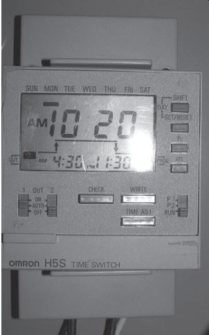
FIG. 12 Individual electronic timers with a wide range of functions and
timing features.
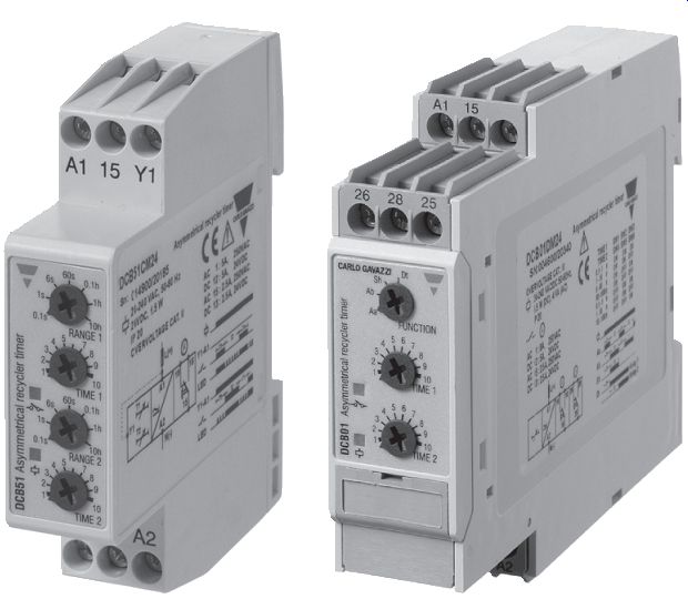
FIG. 13 Example of electronic timer modules.
Electronic timers come in four basic design capacities. On-delay timers provide timing functions just as the electromechanical timers do, but with a higher degree of accuracy and repeatability. Off-delay timers also provide the timing function after the control signal is removed, as does the electromechanical timer. Interval timers are also called one-shot timers. With this timing sequence, the contact closure, whether dry contact or electronic conduction, occurs immediately after the control signal is applied. After a preset time, the contact reverts to its original condition and the timer waits for another signal to change its output again. The last type of timer is called a recycler timer. This timer cycles its output contact open and closed for preset intervals until the control signal is removed from the input. Symmetrical timers have equal on and off times for the output contacts as long as the input signal is present. The asymmetrical timer has adjustable times for the on and off portion of the output closure. See FIG. 13 for the various individual solid-state timers. Some electronic timers are able to provide all these various functions within a single relay. The relay is microprocessor driven and fully programmable.
SUMMARY
Relays are used to control various loads from other electrical circuits. They may be used to operate large values of DC or AC power or simply multiply the electrical circuit function. Contacts can be normally open (NO) or normally closed (NC) or convertible from one form to another.
Things to consider when ordering include:
• control voltage and value.
• contact ratings in current and voltage, number of contacts, NO, NC, or SPDT, and so on.
• whether open contacts, enclosed contacts, or solid-state, no-contact movement are important.
• whether the relay needs very fast speed as in SSRs or whether physical isolation is more important as in electromechanical relays.
QUIZ
1. A mousetrap may be compared with the gate trigger action of an SCR. Indicate whether this statement is true or false, and explain your reasoning.
2. What is the major difference between an electromechanical relay and an SSR?
3. Describe various relay control and load conditions.
4. How are relays used in industrial controls?
5. Basically, what is an SCR?