AMAZON multi-meters discounts AMAZON oscilloscope discounts
GOALS:
• list the steps in the operation of a DC motor control with interlocked forward and reverse pushbuttons.
• explain the principle of dynamic braking.
• describe the operation of a CEMF motor controller with dynamic braking.
Industrial motor installations often require that motors be stopped quickly and that the direction of rotation be reversed immediately after stopping. To achieve this operation, electrically and mechanically interlocked pushbutton stations connected to relays are used to disconnect the armature from the supply source. The armature is then connected to a low value of resistance. Because the inertia of the armature and connected load causes the armature to continue to revolve, it acts as a loaded generator. As a result, the armature is slowed in speed. This action is called dynamic braking.
Reversal of motors and dynamic braking are operations used in special equipment such as cranes, hoists, railway cars, and elevators.

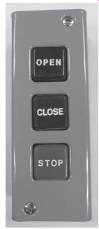
FIG. 1 A forward, reverse, stop pushbutton station.

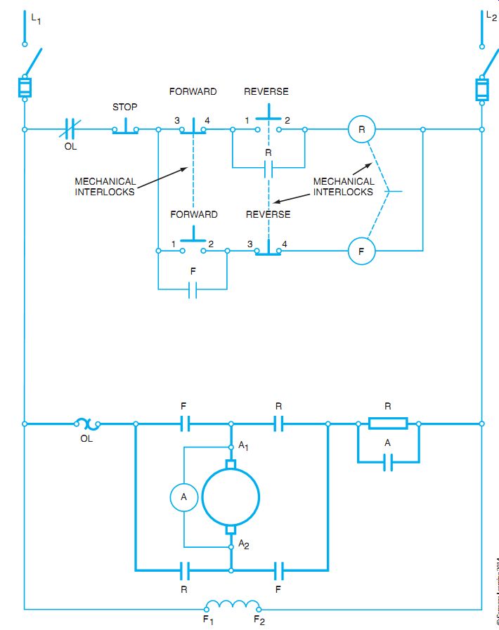
FIG. 2 Electrically and mechanically interlocked control and powered circuit
for reversing motor.
MOTOR-REVERSAL CONTROL
A DC motor is reversed by reversing the armature connections. The type of compounding is not affected by this method of obtaining reversal.
The pushbutton control station illustrated in FIG. 1 is the type used for motor reversal. The forward and reverse buttons are mechanically interlocked so that it is not possible to operate these buttons at the same time.
Description of Operation Forward Starting. When the forward button is pressed, the normally open, forward momentary contacts close and the normally closed, forward momentary contacts open. The control circuit is shown in FIG. 2. The forward contactor coil is energized from L1 through the overload contacts, stop button, forward pushbutton contacts 1-2 (when closed), and reverse button contacts 3-4 through the forward contactor coil to L2. The forward (F) contacts are a holding circuit in the forward pushbutton. In the power circuit (FIG. 2), the F contacts of the forward energized contactor close and thus complete the armature circuit through the starting resistance. The normal CEMF starter sequence of operations then continues to completion.
Reverse Operation. If the reverse pushbutton is pressed, contacts 3-4 of the reverse button open and thus de-energize the forward contactor coil F. In addition, the F contacts are opened as well as the sealing F contacts. Pressing the reverse button also completes the circuit of the reverse contactor coil (R) that closes the R contacts. The motor armature circuit is now complete from L1 to A2 and A1 to L2 (FIG. 2). The armature connections are reversed, and the armature rotates in the opposite direction. It is impossible for the reverse contacts to close until the forward contacts are open, because of the electrical and mechanical interlocking system used in this type of control circuit. The mechanical interlocks are shown by the broken lines between the R and F coils in FIG. 2.
Dynamic Braking
The purpose of dynamic braking is to bring a motor to a quicker stop. To do this, there must be a method to quickly use the mechanical energy stored in the momentum of the spinning armature after the main switch is opened. One method is to change the function of the motor to that of a generator. (A generator converts mechanical energy into electrical energy.) At the instant the motor is disconnected from the line, a resistor is connected across the motor armature. The resistor loads the motor as a generator, dissipates the electrical and therefore the mechanical energy, and slows the motor quickly.
DYNAMIC BRAKING USED IN A CEMF CONTROLLER
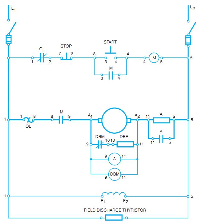
As an example, the principle of dynamic braking is shown by following the steps in the operation of an elementary CEMF controller (FIG. 3).
This analysis emphasizes the dynamic braking operation rather than the details of the circuit, which were presented previously. The dynamic braking magnetic (DBM) coil is designed so that its only function is to ensure a positive closing of the normally closed dynamic braking contacts 9-10. If the main coil M is energized, the dynamic braking contacts 9-10 open from the Normally closed condition, and contacts 8-9 of M are closed, although the dynamic braking coil is also energized.
When the start button is pressed, the control coil M is energized, contacts 8-9 of M close, and the motor starts and accelerates up to normal speed by the CEMF method. At the instant the M control relay is energized, the DBM coil energizes and the normally closed, dynamic braking contacts 9-10 open. As a result, the dynamic brake resistor (DBR) connection across the armature is broken.
Stopping
When the stop button is pressed, relay control coil M is de-energized, and M contacts 8-9 open the armature circuit, de-energize the DBM coil, and close the dynamic braking contacts 9-10.
These contacts connect the dynamic braking resistor directly across the armature. Because the shunt field is still connected across the line and receiving full excitation, the high CEMF generated in the armature causes a high load current through the dynamic brake resistor. The heavy load current dissipates the stored mechanical energy in the armature acting as a heavily loaded generator, with the result that the motor slows to a stop. Braking action decreases as the armature speed decreases.

FIG. 3 Elementary diagram for a DC CEMF controller.
Field Discharge Resistor
When using the CEMF controller and dynamic braking, a field discharge resistor must be added. When the shunt field is disconnected from the supply voltage, its magnetic field begins to collapse. The quick collapse of the magnetic field produces a very large "inductive kick" voltage-possibly thousands of volts. If it does not have a discharge path, the high voltage actually begins to break down the field winding insulation. Normally the discharge path is through the armature, which allows a slower collapse and keeps the voltage small. A field discharge resistor is a thyristor-type device that conducts when the voltage across it is high enough, but has a high resistance to normal line voltage. The collapsing magnetic field's voltage can discharge through the field discharge resistor (FDR) without damaging the field windage.
SUMMARY
FIG. 2 shows the reversing circuit with electrical pushbutton interlocks and mechanical interlocks between the forward and reverse contactor. The motor is reversed by reversing current flow through the armature but keeping the shunt field current in the same direction.
Dynamic braking is used when slowing the motor. As the armature is disconnected from the power source, a dynamic braking resistor is connected across the armature. The armature is still spinning and the shunt field is still energized, so the armature acts as a generator. The resistor provides a current path for the generated current and slows the armature as it works as a genera tor. A field discharge resistor is also used to prevent the sudden collapse of the shunt field flux as it is disconnected from the line power.
QUIZ
1. How can DC motors be reversed without changing the type of compounding?
2. What interlocking is necessary on the forward and reverse pushbuttons to avoid short circuits? _
3. What will happen if the forward and reverse relays are energized at the same time?
4. How many contacts are required on the forward relay? ___
5. What are two applications requiring motor reversal?
6. How can a motor be shut down quickly without using a mechanical brake? _
7. When is dynamic braking applied? ____
8. How does dynamic braking slow a motor?_____
9. If an electromagnetically operated brake is connected in series with the armature, how is it operated?
10. Name two installations in which dynamic braking is used.__