AMAZON multi-meters discounts AMAZON oscilloscope discounts
GOALS:
• explain the operation of the CEMF method of acceleration for a DC motor.
• use elementary wiring diagrams, panel wiring diagrams, and external wiring diagrams.
• explain the ratings of starting and running protection devices.
• describe the operating principles of DC variable speed motor drives.
• state how above and below DC motor speeds can be obtained.
• list the advantages of DC variable speed motor drives.
• describe how solid-state devices can replace rheostats.
• make simple drawings of DC motor drives.
• list the advantages of using thyristors.
Although manual starters are still used, most industrial applications use automatic motor control equipment to minimize the possibility of errors in human judgment. To install and maintain automatic motor control equipment, the electrician must be familiar with three kinds of electrical circuit diagrams:
• schematic wiring diagrams
• panel wiring diagrams
• external wiring diagrams
The electrical schematic wiring diagram uses symbols and a simple plan of connections to illustrate the scheme of control and the sequence of operations.
The panel wiring diagram shows the electrical connections throughout all parts of the controller panel and indicates the external connections. All control elements are represented by symbols but are located in the same relative positions on the wiring diagram that they actually occupy on the control panel. Because of the maze of wires shown on the panel wiring diagram, it is difficult to use for troubleshooting or for understanding the operation of the controller.
For this reason, the electrical schematic wiring diagram presents the sequence of operations of the controller, and the panel diagram is used to locate problems and failures in the operation of the controller.
The external wiring diagram shows the wiring from the control panel to the motor and to the pushbutton stations. This diagram is most useful to the worker who installs the conduit and the wires between the starter panel and the control panel and motor.
CEMF METHOD OF MOTOR ACCELERATION CONTROL
The CEMF produced by the rotor is low at the instant a motor starts. As the motor accelerates, this CEMF increases. Refer to voltage differential in the "Starting Current and CEMF" section in Guide 1. The voltage across the motor armature can be used to activate relays that reduce the starting resistance when the proper motor speed is reached.
Starting and Running Protection for a CEMF Controller
Starting protection for a CEMF controller is provided by fuses in the motor feeder and the branch-circuit line of the motor circuit. These fuses are rated according to Article 430 of the National Electrical Code.
Running protection for a controller, as defined in Part III of NEC Article 430, is provided by an overload thermal element connected in series with the armature. The thermal element is rated at 115% to 125% of the full-load armature current. As covered in NEC 430.32, if the current exceeds the percent of the rated armature current value, heat produced in the thermal element causes the bimetallic strip to open or trip the thermal contacts that are connected in the control circuit. The value of current during the motor start-up period does not last long enough to heat the thermal element sufficiently to cause it to open.
MOTOR CONTROL CIRCUIT
Starting the DC Motor
Refer to FIG. 1. Close the main line switch before pressing the start button. After the start button is pressed, control relay M becomes energized. The control circuit is now complete from L1 through the thermal overload (OL) contacts 6-7, through the start button contacts 7-8, and through the normally closed stop button contacts 8-9 to L2. The lower auxiliary sealing contacts 7-8 of relay M also close and bypass the start button. As a result, the start button may be released without disturbing the operation.
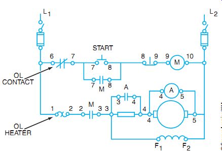
FIG. 1 Elementary diagram of a DC CEMF controller.
When the main contacts 2-3 of contactor M are closed, the motor armature circuit is complete from L1 through overload thermal element contacts 1-2, through contacts 2-3 of relay M, through the starting resistor, and through armature leads 4-5 to L2. The shunt field circuit F1-F2 is connected in parallel with the armature circuit. Contacts 3-4 of CEMF contactor A remain open at start-up because a high inrush current establishes a high voltage drop across resistor 3-4. This leaves only a small voltage drop across the armature and the A contactor coil until acceleration is achieved. As the CEMF builds across the armature, it acts like a resistor that drops a larger percentage of the applied voltage, thus providing a voltage drop for the A coil and the A contacts 3-4 close to bypass current around the starting resistor.
Connecting the Motor across the Line
The CEMF generated in the armature is directly proportional to the speed of the motor.
As the motor accelerates, the speed approaches the normal full speed, and the CEMF increases to a maximum value. Relay A is calibrated to operate at approximately 80% of the rated voltage.
When contacts 3-4 of relay A close, the starting resistance 3-4 is bypassed, and the armature is connected across the line.
Running Overload Protection
A thermal overload relay contains two circuits. One circuit is in series with the armature and has the armature current flowing through its thermal sensor or heating element. The second circuit of the overload relay is the control circuit with a control contact. If the contact opens, because of excessive heat in the thermal heater, the control circuit will be interrupted and stop the motor. A thermal overload relay unit is shown in FIG. 2. The schematic diagram is shown in FIG. 3.
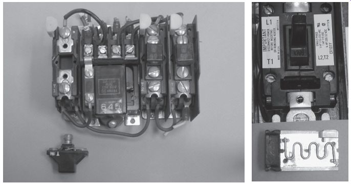
FIG. 2
(A) A melting alloy-type overload relay with the left heater removed. (B) A
bimetal-type overload assembly with the heater removed (under the bimetal relay).
Refer to FIG. 1 for the following explanation. When the load current of the armature exceeds the rated allowable percent of the full-load current, the overload thermal element (points 1-2) heats up and opens contacts 6-7 in the control circuit. Control relay M is de-energized, and main contacts 2-3 of M open and disconnect the motor from the line.
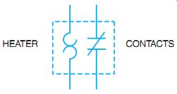
FIG. 3 Schematic symbols for a thermal overload relay. The heater and
contacts together make up the overload relay.
Stopping the Motor
When the stop button is pressed, the control circuit is broken at points 8-9. The same shutdown sequence occurs as in the case of the overload condition discussed previously. The sealing circuit 7-8 is broken in each case.
The advantage of this type of automatic starter is that it does not supply full voltage across the armature until the speed of the motor is correct. The starter eliminates human error that may result from the use of a manual starter.
PANEL WIRING DIAGRAM
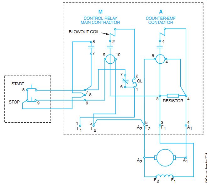
FIG. 4 Panel wiring diagram for a DC CEMF motor controller.
FIG. 4 shows the same CEMF control circuit presented in FIG. 1. However, the panel wiring diagram locates the wiring on the panel in relationship to the actual location of the equipment terminals on the rear of the control panel. Troubleshooting or checking original installations requires an accurate comparison of the elementary schematic diagrams and panel diagrams. The electrician should use a system of checking connections on the diagram with the actual panel connections. For example, a colored pencil may be used to make check marks on the diagram as each connection is properly traced on the panel and compared to the diagram.
CONDUIT OR EXTERNAL WIRING PLAN
All necessary external wiring between isolated panels and equipment is shown in the conduit plan (FIG. 5). The proper size of conduit, size and number of wires, and destination of each wire are indicated on this plan. An electrician refers to this plan when completing the actual installation of the CEMF controller.
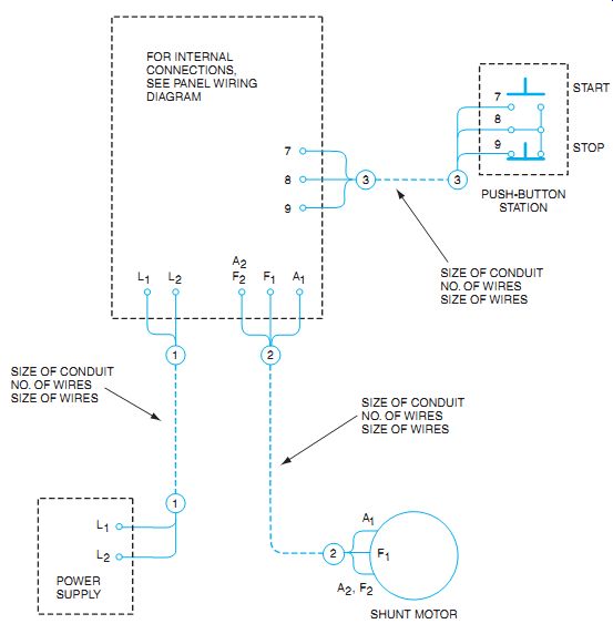
FIG. 5 Conduit or external wiring plan for a CEMF controller.
DC ADJUSTABLE SPEED DRIVES
DC adjustable speed drives are available in convenient units that include all necessary control and power circuits.
Some machinery requirements are so precise that some AC variable frequency drives may not be suitable. In such cases, DC motors provide characteristics that are not available on AC motors. A DC motor with adjustable voltage control is very versatile and can be adapted to a large variety of applications.
In the larger horsepower range, the motor-generator set used to be one of the most widely used methods of obtaining variable-speed control. The set consists of an AC motor driving a DC generator to supply power to a DC motor. Such motor-generator set drives, sometimes called Ward-Leonard systems, were used in early DC motor control and continued to be installed until the 1980s, to control the speed of the motor by adjusting the power supplied to the field of the generator, and, as a result, the output voltage to the motor (FIG. 6). The generator field current can be varied with rheostats, as shown, or by variable transformers supplying a DC rectifier, or automatically with the use of solid-state controls. When it is desirable to control the motor field as well, similar means are used. Many of these systems are still in operation, but one is rarely installed as a new system.
The speed and torque of the system shown in FIG. 6 can be controlled by adjusting the voltage to the field, or to the armature, or both. Speeds above the motor base speed (nameplate speed) are obtained by weakening the motor shunt field. Speeds below the motor base speed are obtained by weakening the generator field. As a result, there is a decrease in the generator voltage supplying the DC motor armature. The motor should have a full shunt field for speeds lower than the base speed, to give the effect of continuous control, rather than step control of the motor speed.
The motor used to furnish the driving power may be a three-phase induction motor, as shown in FIG. 6. After the driving motor is started, it runs continuously at a constant speed to drive the DC generator.
The armature of the generator is coupled electrically to the motor armature as shown.
If the field strength of the generator is varied, the voltage from the DC generator can be con trolled to send any amount of current to the DC motor. As a result, the DC motor can be made to turn at many different speeds. Because of the inductance of the DC fields and the time required by the generator to build up voltage, extremely smooth acceleration is obtained from zero r/min to speeds greater than the base speed.
The field of the DC generator can be reversed automatically or manually, with a resulting reversal of the motor rotation.
The generator field resistance can be changed automatically by using SCRs (or thyristors) or time-delay relays operated by a CEMF across the motor armature. The generator field resistance can also be changed manually.
Electrically controlled, variable speed motor drives offer a wide choice of speed ranges, torque, and horsepower characteristics. They provide a means for controlling acceleration and deceleration, and methods of automatic or manual operation. A controlling tachometer feed back signal may be driven by the DC motor shaft. This is a system refinement to obtain a preset constant speed. This method depends on the type of application, speed, and degree of response desired. In addition to speed, the controlling feedback signal may be set to respond to pressure, tension, shock, or some other transducer function.
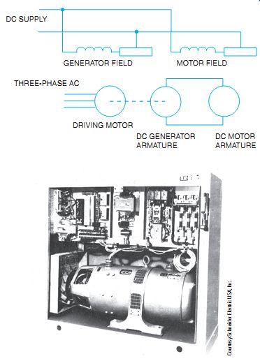
FIG. 6 (A) Basic electrical theory of a DC motor-generator, variable speed
control system. (B) Packaged motor generator with DC variable speed control
system supplied from AC.
One of the most advantageous characteristics of the motor-generator set drive is its inherent capability to regenerate. In other words, when a high-inertia load overdrives the motor, the DC motor becomes a generator and delivers reverse power. For example, assume the DC motor is running at base speed. If the generator voltage is decreased by adjusting the rheostat to slow the motor, the motor counter-voltage will be higher than the generator voltage, and the current reverses. This action results in reverse torque in the motor, and the motor slows down. This process is called dynamic braking. This dynamic feature is very desirable when used on hoists for lowering heavy loads, metalworking machines, textile and paper processing machines, and in general industry for the controlled stopping of high-inertia loads. Multiple motor drives are also accomplished with this type of motor-generator drive.
Motor-generator set drives using automatic regulators have been used for years for nearly every type of application. A higher degree of sophistication in controls has been developed, making it possible to meet almost any desired level of precision or response.
STATIC MOTOR CONTROL DRIVES
Despite the previous use of the motor-generator drives, rotating machines were required to convert AC to mechanical power. As a result, the combined efficiency of the set is rather low; it requires the usual rotating machine maintenance, and it is noisy. Static DC drives now being used have no moving parts in the power conversion equipment that converts (rectifies) and controls the AC power (Figures 7 and 8). The solid-state devices are used for controlled conversion of AC line power to DC.
The basic theory for obtaining DC motor speeds below and above base speed is the same as with a motor-generator set. Only the method of controlling the voltages and field strengths differs. For example, in FIG. 9, the armature is supplied with DC rectified from an AC source.
The AC is rectified by the use of the SCR in the controlled circuit to obtain DC. The gate of the thyristor turns on the SCR at the proper portion of the half-wave, thereby controlling the motor below base speed. FIG. 9 is a simplified circuit for the purpose of illustration. The field strength would be held at its fullest strength in a similar manner. For speeds above the motor base speed, the field control can weaken field strength with full armature voltage. The feedback tachometer maintains a preset speed.
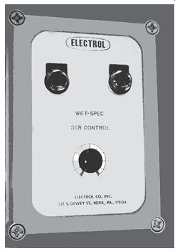
FIG. 7 Control panel for SCR- controlled DC motor drive.
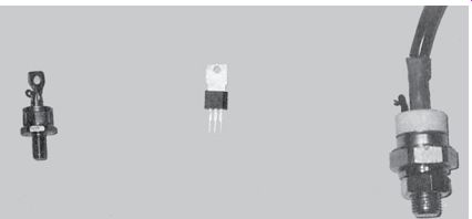
FIG. 8 SCRs in various sizes.
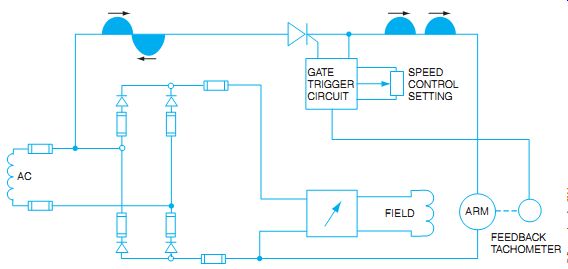
FIG. 9 Single-phase, half-wave armature controlling a small motor.
In FIG. 9, the SCR is controlled by the setting of the potentiometer, or speed control.
This varies the "on" time of the thyristor per AC cycle, and thus varies the amount of average current flow to the armature. When speed control above the base speed is required, the rectifier circuit in the field is controlled by SCRs, rather than diodes.
The SCR, or thyristor, can control all the positive waveform or voltage through the use of a method called phase shifting. Covering the theory of the method is beyond the scope of this guide.
The SCR is probably the most popular solid-state device for controlling large and small electrical power loads. The SCR is a controlled rectifier that controls an electric current. It will not conduct when the voltage across it is in the reverse direction.
It will conduct only in the forward direction when the proper signal (voltage) is applied to the gate terminal (see FIG. 10). The gate is normally controlled by electronic pulses from a control circuit.
The gate will turn the SCR on but will not turn it off in a DC circuit. To turn the anode-cathode section of the SCR on (close the switch), the gate must be the same polarity as the anode with respect to the cathode. After the gate has turned the SCR on, it remains on until the current flowing through the power circuit (anode-cathode section) is either interrupted or drops to a low enough level to permit the device to turn off. The anode-to-cathode current must fall below the holding current level. The holding current, or maintaining current, is the amount of current required to keep the SCR turned on. The SCR performs the same function as a rheostat would in controlling motor field strengths or voltage to an armature. It is similar to a variable resistance because it can be adjusted throughout its power range. The SCR control has replaced the rheostat because it is smaller in size for the same current rating, more energy efficient, and cheaper.
SUMMARY
DC motors need controls to start, stop, protect, and adjust the speed and torque of the motor.
The systems used must comply with the NEC and also have approval from testing firms such as Underwriters Laboratories, Inc. The motors must be protected from overheating and causing damage to the motor and the surrounding area. This guide introduced the two general styles of wiring diagrams: the schematic, which shows the electrical operating sequence of the components, and the wiring diagram, which shows the physical relationship of the equipment. Motor generator sets were presented to familiarize you with the possible sources of DC control. At present, much of the control is done by solid-state DC electronic drives.
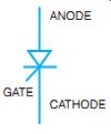
FIG. 10 Schematic symbol for an SCR.
QUIZ
Select the correct answer for each of the following statements, and place the corresponding letter in the space provided.
1. The least important plan or diagram in troubleshooting motor controls is probably the _____
a. electrical schematic plan.
b. panel diagram.
c. external conduit plan.
d. layout of the area in which the controllers are installed.
2. The best diagram to use for determining how a controller operates is the ____
a. electrical schematic plan.
b. panel plan.
c. external plan.
d. architectural plan.
3. The physical location of control wires is shown on the
a. electrical schematic plan.
b. architectural plan.
c. conduit plan.
d. panel wiring diagram.
4. The DC CEMF controller results from the automatic actions of the _
a. applied voltage.
b. changing voltage across the armature.
c. changing voltage across the field.
d. starting current.
5. Overload protection is the same as _
a. starting protection.
b. mechanical protection.
c. electrical protection.
d. running protection.
6. Overload contacts open the circuit when the motor current reaches _
a. 85% of full load.
b. 100% of full load.
c. 125% of full load.
d. 150% of full load.
7. In the event a motor is allowed to exceed the permissible value, it is protected by _
a. starting protection.
b. fuses.
c. an overload thermal element.
d. the stop button.
8. With the disconnect switch closed, the shunt field in FIG. 1 is placed across the line when the
a. A contact closes.
b. disconnect switch is closed.
c. M contact closes.
d. start button closes.
9. In FIG. 1, contact A is closed when the
a. start button is closed.
b. stop button is opened.
c. A coil is de-energized.
d. A coil is energized.
10. The motor in FIG. 1 is placed across the line when
a. the start button is closed.
b. the disconnect switch is closed.
c. contact A is closed.
d. contact M is closed.
11. What is the DC motor base speed? ___
12. How is the speed of a DC motor controlled above the base speed? __
13. How is the speed of a DC motor controlled below the base speed? __
14. How may an SCR replace a rheostat?___
15. List the advantages of using thyristors in the motor drive control. __