AMAZON multi-meters discounts AMAZON oscilloscope discounts
GOALS:
• identify the major sections of an electronic DC motor drive.
• determine the operating features available to the end user.
• describe acceleration and deceleration and braking techniques.
• explain the operating concepts of DC drives for different motors.
DC motors are used in a variety of applications for exact speed control and for high torque requirements that have not readily been available with AC motors. The DC motor and drive system has been available for some time, and many industrial installations are dependent on the operating characteristics of the motor and associated drive system. Until the more recent introduction of the variable frequency drive (VFD), and especially the vector drive, precise speed control and acceleration, deceleration, and electrical braking were not available with AC motors.
DC DRIVE BASICS
The DC controller is based on the same principles as the older electromechanical systems for controlling DC motors. In other words, to control the speed, the current is reduced to the armature of the DC motor to reduce the speed on the motor below normal full operating design speed, and the main field is weakened for speeds above normal speed. The difference between the older starters and the electronic one is efficiency and much tighter control. The old starters inserted resistance into the armature circuit to reduce the voltage and current to the armature and therefore dissipate the energy in the resistors and waste the power, making it inefficient.
There was little feedback to the controller, so there was no adjustable process to control the exact speed of the motor. With electronics, there is little wasted energy and much more precise control of actual motor operations.
DC DRIVE BLOCK CIRCUITS
The DC motor requires the application of direct current to the actual motor windings. The DC drive controller will change, or rectify, the available AC to DC and adjust the DC to control the motor operations. Two general schemes are used to deliver the DC to the motor. Each of the methods provides the same basic functions. See FIG. 1 for the block diagram of a controller. One block provides DC to the field, and one block supplies controlled DC to the armature.
A set point control adjusts the firing of output silicon- controlled rectifiers (SCRs or triodes for alternating current [TRIACs]). Feedback circuits tell the controller what the motor is doing.
SIMPLE CONTROL
One method used for small motors with only basic speed and torque requirements is to use only half of the incoming AC, rectify it with a half-wave rectifier system, and deliver half-wave DC to the motor armature (see FIG. 2). In most cases, the shunt field is supplied by a full-wave bridge circuit that supplies rectified DC to the motor field. This can be an adjustable voltage also if the motor has to operate above rated speed. The armature power is typically controlled by an SCR that is turned on at different points in the waveform to adjust the voltage to the motor armature to control the speed. In the case of a motor where exact speed control and high torque are not critical, the half-wave controller may be sufficient and most economical. The firing of the SCR or the gate control may be of the amplitude control or the phase control type. The amplitude control only has control over the first half of the sinewave, as seen in FIG. 3. This is the least costly control scheme and provides the least amount of control. The more common type is the phase control method that allows the half-wave almost 180 electrical degrees of control (see FIG. 4).
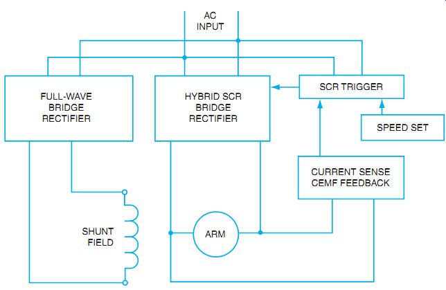
FIG. 1 Block diagram of electronic controller used for a shunt motor.
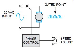
FIG. 2 Phase control controls output for nearly 180°.
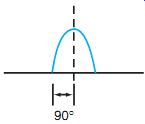
FIG. 3 Amplitude control has a control range for the first 90° of half-sinewave
(0 to 90° control).
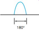
FIG. 4 Phase control has control for nearly the full 180° of the half-
sinewave (0 to 180° control).
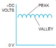
FIG. 5 DC voltage with ripple content.
DC POWER SUPPLIES
In almost all situations currently encountered, the DC voltage sources needed to supply motors and other electrical apparatus are produced by solid-state rectifiers that convert alternating current (AC) to direct current (DC). There are several different methods used to rectify the AC and create various levels of DC output from the rectifier circuits at different degrees of smoothed (low-ripple) DC. As in DC generators where the DC is produced through commutation of a generated AC wave, the commutated DC is not always a smooth DC voltage as you would see from a battery output. Electronic rectifier circuits also produce a DC with different percentages of ripple to the DC voltage. The small-ripple value of the DC voltage can be seen in FIG. 5. As you can see, the voltage output is DC, meaning that the current always flows in one specific direction, but it flows at unequal amounts. There are, in fact, a peak and a valley to the DC voltage. This fluctuating DC is sometimes referred to as the AC component (fluctuating component) of the DC wave. The rectifier circuit can be as simple as a single diode used with a single-sinewave AC input, as in FIG. 6. The output waveform is DC half-wave rectification. This means that only half of the AC voltage is used and the other half of the AC input voltage is blocked, or not used. The DC value of the output voltage is approximately 0.314 (or p) times the peak AC value of the input. If the peak of the AC input is 100 volts, a meter set to DC on the output would measure approximately 31.4 VDC. If you look at the DC with an oscilloscope, it appears very bumpy; in other words, it has a lot of ripple. When you measure the AC (fluctuating component) of the waveform using a meter that blocks the DC level, you measure near the value calculated by AC peak × 0.385, or about 38.5 volts in this example. The percent ripple is calculated by the formula
% ripple = AC ripple component/DC value
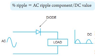
FIG. 6 One-half wave rectifier
uses a single diode.
Compare the DC value to the AC value for a half-wave rectifier and you get approximately 121% ripple. We discuss how to filter the DC to reduce the ripple at a later time.
Another rectifier circuit that provides more DC for a specific AC input is known as the full-wave rectifier circuit. This circuit requires two diodes and the use of a center-tapped secondary AC transformer. By viewing FIG. 7, known as a center-tapped, full-wave rectifier circuit, you see that the full input voltage is used in the DC output. In this circuit both halves of the AC input waveform are used to supply the DC load. For a half cycle of input voltage, the top of the circuit is the most positive part of the circuit, and current flows from the center tap of the transformer, through the load, through diode 1, back to the source. In the other half cycle, the current again flows from the center tap through the load, through diode 2, back to the bottom side of the source transformer, which is now the most positive point of the circuit. In this circuit the DC value of the output voltage is twice the value of the half-wave rectifier. The output is now approximately 0.637 (2p) times the peak of the AC input voltage. The AC ripple content has decreased to AC peak × 0.305. There is less nonconducting time for the DC voltage, and the ripple content has decreased. In fact, with a higher DC content and a lower fluctuation, or AC component, the ripple content has decreased to approximately 48%. With less ripple, less filtering is needed to create smooth DC voltage output.
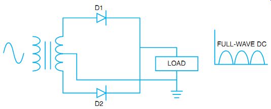
FIG. 7 Center-tapped, full-wave rectifier circuit.
Yet another type of rectifier circuit is the full-wave bridge circuit, as in FIG. 8. As the name implies, the DC uses the full wave of the AC input. The bridge refers to the style of circuit converting AC to DC. With the use of four relatively inexpensive diodes, the expensive center tapped transformer can be eliminated. See FIG. 9 for each half-cycle current path through the bridge of diodes. The output of the bridge has the same values of DC as the center-tapped, full-wave rectifier if you ignore the small diode voltage drops of the rectifiers. The waveform of the DC output has a frequency as well as a ripple content. The ripple frequency is determined by the number of positive peaks that occur in 1 second. In both full-wave rectifier circuits, the number of positive peaks that occurs is twice that of the AC input-positive peaks, as verified in FIG. 12. If the input AC waveform is at a standard 60 Hz, or 60 positive peaks per second, the full-wave DC has 120 positive peaks for a ripple frequency of 120 Hz. By comparison, in the half-wave rectifier the input frequency is equal to the output DC frequency. Remember the AC component does not reverse the direction of current flow but only changes the value of the DC. The frequency relates to the AC component of the DC output.
In DC motor control, the fields of the DC motors are often supplied by a steady DC value provided by diode rectifier circuits. To smooth out the DC level and make it more consistent, the ripple effect of the DC has to be filtered or smoothed. With a higher ripple frequency and smaller ripple content, as in full-wave rectification, the filtering can be done effectively and efficiently with capacitor filters.
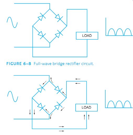
FIG.
8 Full-wave bridge rectifier circuit. FIG. 9 Full-wave bridge with current
directions for each half cycle.
Capacitive filtering uses a capacitor or set of capacitors in parallel with the load.
The circuit in FIG. 10 shows that the capacitor charges up to the peak of the waveform as current flows through the load and also charges the capacitor. In the half cycle, when the sup ply current path is blocked, the capacitor begins to discharge through the load in the direction shown in FIG. 11. The effect is to fill in the gap of nonconducting diode time and reduce the ripple and increase the DC value of voltage. By using the same concept on the full-wave bridge rectifier circuit of FIG. 12, the DC value becomes smoother and the ripple becomes less objectionable. With the load consisting of the motor coils producing the magnetic field, the steady DC makes the motor performance more reliable and predictable.
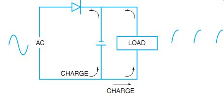
FIG. 10 Capacitive filter with charge current directions.
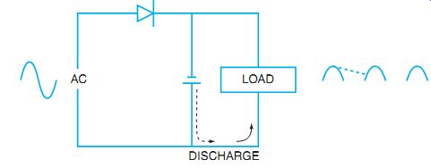
FIG. 11 Capacitive filter with discharge current directions.
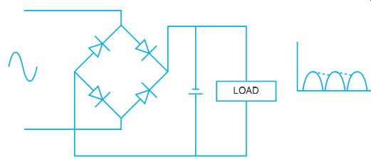
FIG. 12 Full-wave bridge needs less filtering than a half-wave rectifier.
Most DC electronic speed controls use a separate source to provide steady DC to the fields. These supplies are made of full-wave bridges or more typically use a three-phase rectifier sys tem, as in FIG. 13. In this system, all three phases are rectified, and the DC level remains high and the ripple percentage is very low. This means the DC supply needs very little filtering.
The DC supplies that are used to provide the DC for the armature are constructed a little differently. The reason for the difference is the method used to control the speed of a DC motor.
For speeds below full speed, the method used reduces the voltage applied to the armature while leaving the field at full strength. Therefore, it is necessary to create a variable voltage DC sup ply to control the armature power. For most DC controllers, the primary power tends to be three-phase AC. The schematic diagram in FIG. 14 is used with the addition of a control network that allows the thyristors, such as TRIACs, to be turned on at various times. Essentially, if the TRIACs are gated at various angles, the output DC can be controlled rather precisely. If the TRIACs are turned on at 0°, the output voltage is very high positive, based on the formula
VDC = 1.35 × ACRMS × cosine of the firing angle
With 460 VAC applied and a 0° firing angle, the DC is approximately 620 volts. At a 90° firing angle, the DC voltage is zero because there is just as much positive as negative waveform, and at a 180° firing angle the DC is all negative at -621 volts. Angles between 0° and 90° yield DC between 621 and 0 VDC. This process allows us to control the armature voltage that adjusts the speed of the DC motor.
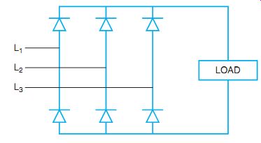
FIG. 13 Three-phase rectifier circuit.
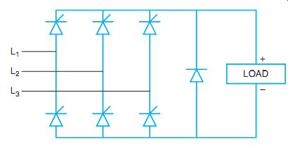
FIG. 14 Thyristors used to control the DC voltage output from a three-phase
source.
As seen in FIG. 14, there is a large diode across the armature connection called a flywheel diode, freewheeling diode, or kickback diode. The diode is connected in the control so that it is reversed biased, blocking current flow, while the normal voltage is applied to the armature.
When the supply DC is turned off, the magnetic field in the armature collapses and creates a large inductive kick voltage, opposite to the applied voltage. This large inductive kick voltage could be enough to break down the motor windings or the motor controller; therefore, the fly wheel diode is forward biased by the inductive kick, and the kick is reduced by allowing current to flow back through the armature windings, which slows the magnetic field collapse.
SAFETY CIRCUITS
In most controllers, a safety circuit monitors the DC field. If this stator field is lost, the motor may accelerate to dangerous speeds, especially with no load. If the field is lost on compound motors, the motor becomes a series motor and operates as a series motor would. The power to the armature must be disconnected. The current to the field can be monitored by placing a low ohm resistor in series with the field. Current flowing to the field passes through the resistor and creates a voltage drop. The voltage drop becomes part of the control circuit for the armature.
If there is no field sensor voltage, the SCR firing circuit for the armature shuts down. Another method is to use a DC current flow sensor called a Hall effect sensor, which is essentially a current transformer specifically designed to sense DC current flow. Again, this sensor provides information to the armature control circuit.
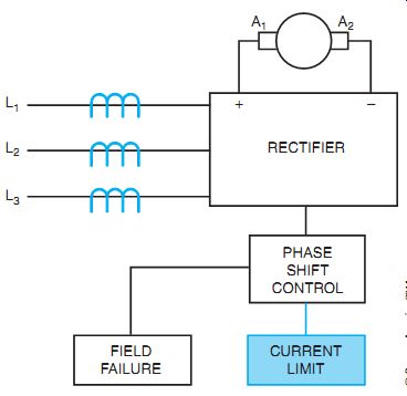
FIG. 15 Current flow to armature is limited.
Another type of safety is the current control to the armature. Because there is only DC resistance to current flow in the windings when the motor is not spinning, the initial current flow to a stopped or stalled motor may be very large. To avoid damaging the motor or the electronic controller, current sensors can be used to adjust the firing angle of the SCRs to control armature current. One method of sensing the cur rent is the same as the field sensor. By placing a low-ohm resistor in series with the armature current, the voltage dropped across the resistor can be used to operate a control point in the firing circuit. If the cur rent is too high, the voltage drop across the resistor is high, and the signal is sent to the controller to reduce the armature current.
Another method is to measure the AC current going into the output SCR output controller. By using AC current transformers, the input current is monitored, which is indicative of the output DC current. When the output is too high, the input monitors send a signal to the controller to reduce the "on" time of the SCRs (see FIG. 15).
SPEED CONTROL AND REGULATION
As mentioned earlier, the speed of the DC motor is easily controlled by adjusting the amount of time the thyristors are allowed to conduct by controlling the "on" time during each cycle.
If the controller is operating in an open loop mode, there is no feedback from the motor to the controller. This means the thyristors will fire as determined by the input control signal or the speed-setting potentiometer. If the motor is to maintain a set speed under varying loads, there must be feedback from the motor to create a closed loop system. Often times the actual speed of the motor is monitored by a tachometer attached to the motor. The tachometer output signal is fed back to the firing control to adjust the firing of the thyristor to compensate for load-induced speed changes. Another method to monitor the exact speed of the motor is to use an armature voltage feedback circuit. This circuit basically measures the exact voltage across the armature. If the motor speed slows down, less CEMF is produced before any change occurs in the control.
This reduced CEMF causes the voltage across the armature to be reduced. The reduction in the armature voltage is fed back to the controller, causing the thyristors to be turned on earlier in the cycle and more current to be sent to the armature.
Internal resistance (IR) compensation is another system designed to improve the speed regulation of a DC motor. The IR of the motor is relatively low. The IR compensation monitors the actual current to the armature by using a small series resistor (see FIG. 16). If the motor speed slows down, less CEMF is produced by the motor. If the firing does not change, more cur rent is allowed to flow to the motor. This IR sensor detects the increased current flow and sends a signal to the thyristor firing circuit to increase the "on" time, thereby increasing motor speed back to the set point, which increases the CEMF back to its original set value. IR compensation is typically one of the parameters set on the controller.
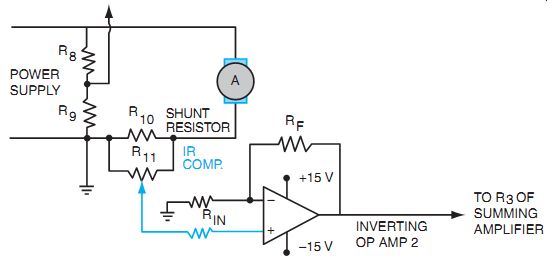
FIG. 16 IR compensation, speed-regulation circuit.
Many controllers have minimum and maximum speed settings. These settings are used to provide for safe operating limits for the motor. The minimum speed is the lowest possible speed, even though the speed control potentiometer is set to zero or the minimum setting. This may be used when a process should not be allowed to completely stop even if the speed is reduced as far as possible. Likewise, the upper end of the speed control is often limited with a maximum speed adjustment. This control sets the maximum allowable speed of the motor even if the controller is capable of higher speeds with the speed-control potentiometer. In addition to the minimum and maximum speed settings, parameters control the acceleration and deceleration of the motors.
Acceleration times can be controlled by setting the ramp-up time from minimum speed to set speed. This feature prevents excessive current draw from the line and reduces electrical stress on the motor and mechanical stress on the driven equipment. Too sudden of an increase can cause the shaft to shear off if the mechanical load is heavy. A safety feature called an electronic shear pin is designed to monitor this type of situation. If the current increase to the motor is too swift, it might be an indication of a jammed motor, and the sudden increase in twisting effort might cause the shaft to shear. The electronic shear pin reacts to the amount-and rate- of current increase to the motor. A smooth acceleration is controlled by gradually increasing the "on" time of the SCRs.
Deceleration is the gradual stopping of the motor. This time can be set to bring the motor from set speed to minimum speed. By slowly decreasing the "on" time of the SCRs, the motor slows gradually, thus reducing the mechanical stress on equipment if the motor were to come to an abrupt stop.
Above-normal (or base) speed can also be obtained within the mechanical limits of the motor by adjusting the shunt field of the motor. If the stator field is weakened, the CEMF produced by the spinning armature is also reduced. This decrease in CEMF allows more current to flow in the rotor. Even with a weakened field, the increased current causes a higher speed.
This higher speed comes at the expense of lower torque. At some point, the weakened field will not react with the high current armature to produce enough torque to keep the motor spinning.
There is a sudden decrease in speed because the breakdown torque point has been reached.
ELECTRICAL BRAKING
Braking of the DC motor can also be accomplished by the controller functions. Two styles of braking can be used: regenerative braking and dynamic braking.
Regenerative braking is a form of electrical braking that provides a reversing voltage to the motor while it is still attached to the spinning load (see FIG. 17). This circuit applies a reverse voltage to the stator, which attempts to drive the motor in the opposite direction. As the rotor attempts to align with the reversed field, a countertorque is produced that brings the motor to a quick stop. As the motor approaches zero speed, the reversed field is removed to prevent the motor from actually reversing.
Dynamic braking is another form of electrical brakes. In this style of braking, a resistor is inserted in the circuit to act as an electrical load for the spinning armature as normal armature current is disconnected. The armature has inertia from the driven load and continues to spin.
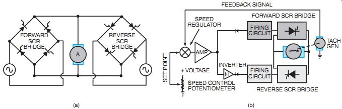
FIG. 17 Regenerative braking.
The DC shunt field is maintained, and the armature now becomes a generator. If the armature is connected to an electrical load, the generator effects cause the rotor to slow with an electrical load attached. The resistor is called a dynamic braking resistor (DBR) and is a high-wattage, low-ohm resistor. It is usually located in a well-ventilated part of the controller so the dissipated heat is easily removed (see FIG. 18).
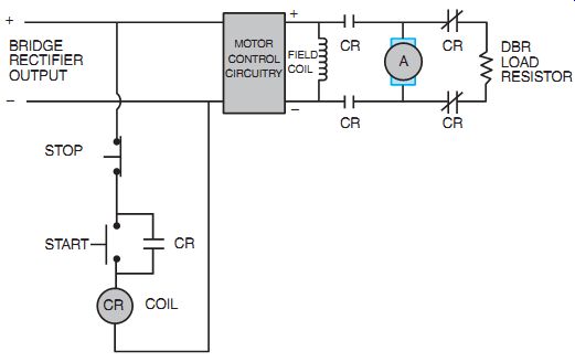
FIG. 18 Dynamic braking circuit.
LOAD CONSIDERATIONS
Mechanical loads are characterized by the requirements of the driven machinery. The torque and horsepower requirements may change with the changing speed of the motor. These loads are classified as (1) constant horsepower, (2) constant torque, and (3) variable torque.
The following parameters are necessary to choose the right controller or to properly set up a DC drive for optimum control:
• Constant horsepower loads require more torque at low speed and less torque at high speed. The product of the torque times the speed must stay constant over varying speeds. Motor drives can be set to adjust the torque requirements based on the speed of the motor to produce a constant horsepower output.
• Constant torque loads have to maintain the same torque over a speed range. The horse power of the motor varies. To overcome a friction load, as in conveyors and extruders, the torque is maintained over all speeds. More horsepower is required to start the load, but the horsepower can be reduced as the load moves up to speed.
• Variable torque loads are loads such as fans and pumps. In this type of load, the torque varies as the square of the speed. As the speed of a pump or fan increases, it does more work and higher torque is required.
SUMMARY
DC drives have many applications and many variables that must be considered when choosing the proper drive for the situation. Be sure you understand the needs of the driven machinery, to deter mine which drive or parameters are important. The drives all work from the same block-equipment approach.
The AC input is converted to DC for the field. The AC is controlled by SCRs and a firing control block to rectify the AC and control the level of DC voltage and current sent to the armature. Various methods are used to provide safety, regulation, and speed setting. See FIG. 19 for DC drive examples.
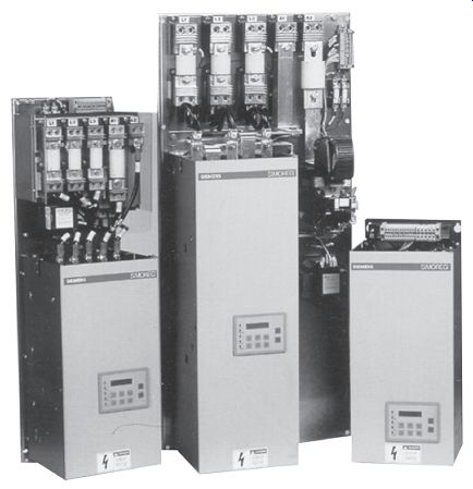
FIG. 19 DC drive examples.
QUIZ
1. Name the concept used to reduce the speed of a DC motor below base speed.
2. What method can be used to increase speed above base speed?
3. Electronic shear pins are used to ___
a. reduce the stress of the current on the motor windings.
b. shut down the motor current if it rises too rapidly.
c. hold the electronic firing of the SCRs to a shear level.
d. break away under mechanical stress.
4. To increase the motor speed, the SCRs are allowed to conduct (more, less). (Circle the correct answer.)
5. Name a disadvantage of a half-wave rectifier system for the motor power.
6. The flywheel diode prevents ___
a. inductive kick damage to the motor and drive.
b. overvoltage conditions from damaging the motor during normal operation.
c. cogging of the motor during slow-speed operations.
d. the negative effects associated with motors that drive flywheel devices.
7. Open-loop control refers to the ___
a. problem of the controller overshooting the design speed.
b. method of measuring the actual current to the rotor.
c. control system that does not provide speed information back to the controller.
d. control system that provides speed information back to the controller.
8. Regulation of a DC motor speed means that the speed ____
a. is held constant with various input frequencies.
b. changes in proportion to the load.
c. changes inversely to the load.
d. stays constant under a varying load.
9. Regenerative braking requires a ___
a. DBR.
b. reverse field control.
c. generator attachment to the motor.
d. load that is able to be stopped immediately.
10. Variable torque loads ___
a. change horsepower, but not torque, over a speed range.
b. change speed, but not horsepower, over the range of the load.
c. never change speed over the horsepower range of the drive.
d. change torque exponentially as the speed changes.
__