AMAZON multi-meters discounts AMAZON oscilloscope discounts
GOALS:
• describe the need for starting controls for DC motors.
• define manual starters used with DC motors.
• describe the two basic types of manual DC motor starters.
• identify the drum controller section and read connection diagrams.
• describe the connections that occur at each first position in forward and reverse of a drum controller.
Manual starters for DC motors are rare because electronic controls are much more efficient and practical. A short review of the manual methods called three-point and four-point starters may be useful, as some electricians may still need to maintain these starting methods.
Two factors limit the amount of current used by a motor that is supplied from a DC source: (1) the counter-electromotor force (CEMF) produced in the rotor by the spinning of the conductors through a magnetic field and (2) the actual resistance of the motor windings.
The wire resistance is typically very low, less than 10 ohms, and the rotor has no CEMF when the rotor is at a standstill or just starting. Therefore, the current is very high at the starting of the DC motor. The same effect is also seen in AC motors, but the introduction of impedance of the motor coils due to AC helps limit the starting current. In DC motors, the need for a starting controller with an in-line resistor or variable rheostat for limiting the starting current was devised. This starting rheostat, or DC motor starter, is described by NEMA (National Electrical Manufacturers Association) as a device used to accelerate the motor to its rated speed in one direction and limit the current to the armature circuit to a safe value during starting and accelerating. Two styles of manual starters were used.
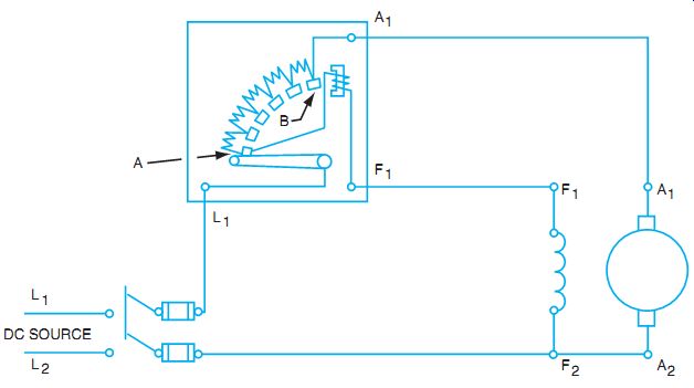
FIG. 1 Connections for a three-terminal starting rheostat.
THREE-TERMINAL STARTER FOR DC MOTORS
A three-terminal starter is shown in FIG. 1, connected to a shunt-wound motor. Note that the tapped resistance is connected in series with the armature, yet the high resistance field receives full voltage immediately upon starting. The idea is to get the field flux at full value immediately so the armature immediately begins producing CEMF as it begins spinning. As the starter is moved from left to right, portions of the armature series resistance are shorted out, and eventually there is no more resistance in series with the armature. The electromagnet on the far right actually holds the arm in the "run" position. If the shunt field has an open circuit at any time, the arm releases the controller arm, causing the motor to stop as a precaution. This "no field" circuit is necessary to prevent a high-speed runaway of the DC shunt motor at no load. In FIG. 2, a compound motor is connected to a three-terminal starter. The only change is the addition of the series field to the diagram.
FOUR-TERMINAL STARTERS FOR DC MOTORS
This slight variation on the three-terminal starter is used if there is a need for variable speed control using a field rheostat (see FIG. 3). As the arm is raised to the first position, the shunt field receives full voltage, yet there is still resistance in the armature circuit. As the arm is moved to the right, resistance is added to the shunt field circuit but removed from the armature circuit.
Because adding resistance to the shunt field circuit reduces the current to the field, the holding electromagnet is not in series with the shunt field but is connected across the line, hence the fourth terminal. This process makes this starter more like an AC starter with "no-voltage" release. If line voltage drops too low, the electromagnet releases the arm, which springs back to stop the motor.
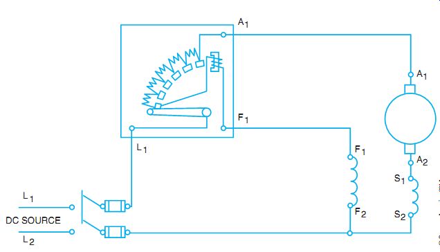
FIG. 2 Three-terminal starting rheostat connected to a cumulative compound
wound motor.
NATIONAL ELECTRICAL CODE FOR MOTOR STARTERS
Part VII in Article 430.82(C) refers to the controller design and the need for starting rheostat controls. Note that 430.89 requires speed limitations on separately excited DC motors and on series motors as well as motor generators and converters that can be driven by DC at excessive speed. Remember that DC series motors that can run at no load may generate runaway speeds and literally throw themselves apart.
DRUM CONTROLLERS
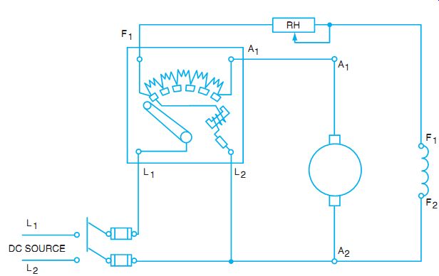
FIG. 3 Connections for a four-terminal starting rheostat
Drum controllers are used when an operator is controlling the motor directly. The drum controller is used to start, stop, reverse, and vary the speed of a motor. This type of controller was used on crane motors, elevators, machine tools, and other applications in heavy industry. As a result, the drum controller had to be more rugged than the starting rheostat.
A drum controller with its cover removed is shown in FIG. 4. The switch consists of a series of contacts mounted on a movable cylinder. The contacts, which are insulated from the cylinder and from one another, are called movable contacts. Another set of contacts, called stationary contacts, is located inside the controller. These stationary contacts are arranged to touch the movable contacts as the cylinder is rotated. A handle, keyed to the shaft for the movable cylinder and contacts, is located on top of the drum controller. This handle can be moved either clockwise or counterclockwise to provide a range of speed control in either direction of rotation. The handle can remain stationary in either the forward or reverse direction due to a roller and a notched wheel. A spring forces the roller into one of the notches at each successive position of the controller handle to keep the cylinder and movable contacts stationary until the handle is moved by the operator.
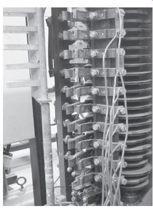
FIG. 4 Drum type of controller showing contact fingers.
A drum controller with two steps of resistance is shown in FIG. 5. The contacts are represented in a flat position in this schematic diagram to make it easier to trace the circuit connections. To operate the motor in the forward direction, the set of contacts on the right must make contact with the center stationary contacts.
Operation in the reverse direction requires that the set of movable contacts on the left make contact with the center stationary contacts.
Note in FIG. 5 that the controller handle can be set to three forward positions and three reverse positions. In the first forward position, all the resistance is in series with the armature. The circuit path for the first forward position is as follows:
1. Movable fingers a, b, c, and d contact the stationary contacts 7, 5, 4, and 3.
2. The current path is from the negative side of the line to contact 7, from 7 to a, from a to b, from b to 5, and then to armature terminal A1.
3. After passing through the armature winding to terminal A2, the current path is to stationary contact 6, and then to stationary contact 4.
4. From contact 4, the current path is to contact c, to d, and then to contact 3.
5. The current path then goes through the armature resistor, to the series field, and then back to the positive side of the line.
The shunt field of the compound motor is connected across the source voltage. On the second forward position of the controller handle, part of the resistance is cut out. The third forward position cuts out all the resistance and puts the armature circuit directly across the source voltage.
In the first reverse position, all the resistance is inserted in series with the armature.
FIG. 6 shows the first position of the controller in the reverse direction. The cur rent in the armature circuit is reversed. However, the current direction in the shunt and series fields is the same as the direction for the forward positions. Remember that an earlier guide showed that a change in current direction in the armature only resulted in a change in the direction of rotation.
The second reverse position cuts out part of the resistance circuit. The third reverse position cuts out all the resistance and puts the armature circuit directly across the source. Drum controllers with more positions for a greater control of speed can be obtained. However, these controllers all use the same type of circuit arrangement shown in this guide.
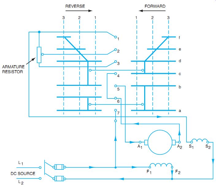
FIG. 5 Schematic diagram of a drum controller connected to a compound-wound
motor.
SUMMARY
Three-terminal and four-terminal starting rheostats are not used much any more. The advent of electronic starters has all but replaced the mechanical starters. The concept of the starter is still used, and the safeguards for motor operation are still important.
DC series motors require a different starting controller than a shunt or compound motor. The holding circuit for the controller is in series with the starting resistance. If there is a low-voltage or no-voltage condition, the starter is returned to the off position. Drum controllers are still frequently used with AC as well as DC motors. It is important to be able to read the connection diagrams and the sequence diagrams on drum-type controllers.
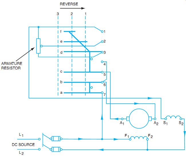
FIG. 6 First positions of controller for reverse directions.
QUIZ
1. What are the two functions of a motor starter?
a. _____
b. _____
2. Show the connections of a three-terminal starting rheostat to a shunt motor.
3. Show the connections of a four-terminal starting rheostat to a shunt motor.
4. Complete the connections in FIG. 7 to show that the cumulative compound-wound motor can be started from the four-terminal starting rheostat. Also connect the field rheostat in the circuit for above-normal speed control.
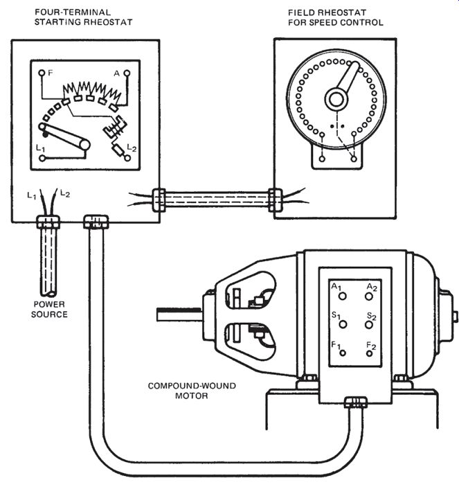
FIG. 7 Connection diagram for question 4.
5. Why is a drum controller used in many industrial applications? ____
6. A series starter with no-load protection is used to prevent the series motor from reaching ____ at low loads.
7. A drum controller provides the following types of control for a DC motor:
__