AMAZON multi-meters discounts AMAZON oscilloscope discounts
GOALS:
• describe the basic operation of a universal motor.
• explain how a single-field compensated universal motor operates.
• explain how a two-field compensated universal motor operates.
• describe two ways in which universal motors are compensated for excessive armature reaction under load.
• state the reasons why DC motors fail to operate satisfactorily from an AC source.
• describe the basic steps in the operation of the following types of motors:
• repulsion motor.
• repulsion-start, induction-run motor.
• repulsion-induction motor.
• state the basic construction differences among the motors in the preceding list.
• compare the motors in the preceding list with regard to starting torque and speed performance.
The electrician may consider a typical DC series motor or a DC shunt motor for operation on AC power supplies. It appears that such operation is possible because reversing the line terminals to a DC motor reverses the current and magnetic flux in both the field and armature circuits. As a result, the net torque of the motor operating from an AC source is in the same direction. However, the operation of a DC shunt motor from an AC source is impractical because the high inductance of the shunt field causes the field current and the field flux to lag the line voltage by almost 90°. The resulting torque is very low.
A DC series motor also fails to operate satisfactorily from an AC source because of the excessive heat developed by eddy currents in the field poles. In addition, an excessive voltage drop occurs across the series field windings due to high reactance.
To reduce the eddy currents, the field poles can be laminated. To reduce the voltage loss across the field poles to a minimum, a small number of field turns can be used on a low reactance core operated at low flux density. A motor with these revisions operates on either AC or DC and is known as a universal motor. Universal motors in small fractional horsepower sizes are used in household appliances and portable power tools.
Repulsion motors are divided into three distinct classifications: the repulsion motor; the repulsion-start, induction-run motor; and the repulsion-induction motor. Although these motors are similar in name, they differ in construction, operating characteristics, and industrial applications.
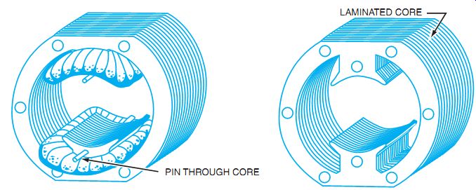
FIG. 1 Field core of a two-pole universal motor.
CONCENTRATED-FIELD UNIVERSAL MOTORS
A concentrated-field universal motor is usually a salient-pole motor with two poles and a winding of relatively few turns. The poles and winding are connected to give opposite magnetic polarity. A field yoke of this type of motor is shown in FIG. 1.
THE ARMATURE
The armature of a typical universal motor resembles the armature of a typical DC motor except that a universal motor armature is slightly larger for the same horsepower output.
CONSTRUCTION FEATURES OF UNIVERSAL MOTORS
The frames of universal motors are made of aluminum, cast iron, or rolled steel. The field poles are generally bolted to the frame. Field cores consist of laminations pressed together and held by bolts. The armature core is also laminated and has a typical commutator and brushes. End plates resemble those of other motors except that in many universal motors, one end plate is cast as part of the frame. Both ball and sleeve bearings are used in universal motors.
SPEED CONTROL
Universal motors operate at approximately the same speed on DC or single-phase AC. Because these motors are series wound, they operate at excessive speed at a no-load condition. As a result, they are usually permanently connected by gears to the devices being driven. Universal motors are speed-regulated by inserting resistance in series with the motor. The resistance may be tapped resistors, rheostats, or tapped nichrome wire coils wound over a single field pole. In addition, speed may be controlled by varying the inductance through taps on one of the field poles. Gear boxes are also used.
DISTRIBUTED-FIELD UNIVERSAL MOTORS
The two types of distributed-field universal motors are the single-field compensated motor and the two-field compensated motor. The field windings of a two-pole, single-field compensated motor resemble the stator winding of a two-pole, split-phase AC motor. A two-field compensated motor has a stator containing a main winding and a compensating winding spaced 90 electrical degrees apart. The compensating winding reduces the reactance voltage developed in the armature by the alternating flux when the motor operates from an AC source. FIG. 2 is the schematic diagram of a compensated universal motor.
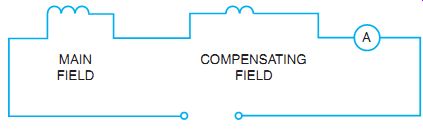
FIG. 2 Schematic diagram of a compensated universal motor.
Speed control of series motors can also be accomplished by using electronic speed controls. The concept is the same as used in series voltage drops; that is, the voltage to the motor is reduced to give a reduced speed. This can be done by using SCRs or triacs to alter the voltage available to the motor.
DIRECTION OF ROTATION
The direction of rotation of any series-wound motor can be reversed by changing the direction of the current in either the field or the armature circuit. Universal motors are sensitive to brush position, and severe arcing at the brushes results from changing the direction of rotation without shifting the brushes to the neutral (sparkless) plane or adding a compensating winding.
CONDUCTIVE COMPENSATION
AC motors rated at more than 0.5 hp are used to drive loads requiring a high starting torque.
Two methods are used to compensate for excessive armature reaction under load. In the conductively compensated type of motor, an additional compensating winding is placed in slots cut directly into the pole faces. The strength of this field increases with an increase in load current and thus minimizes the distortion of the main field flux by the armature flux (called armature reaction, discussed in Unit 1). The compensating winding is connected in series with the series field winding and the armature, as shown in FIG. 3. Although conductively compensated motors have a high starting torque, the speed regulation is poor. A wide range of speed control is possible with the use of resistor-type starter controllers.
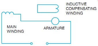
FIG. 3 Connections for an inductively compensated universal motor.
INDUCTIVE COMPENSATION
Armature reaction in AC series motors may also be compensated with an inductively coupled winding, which acts as a short-circuited secondary winding of a transformer. This winding is placed so that it links the cross-magnetizing flux of the armature, which acts as the primary winding of a transformer. FIG. 3 shows the schematic diagram of an inductively compensated universal motor. Because the magnetomotive force of the secondary is nearly opposite in phase and equal in magnitude to the primary magnetomotive force, the compensating winding flux nearly neutralizes the armature cross flux. This type of motor cannot be used on DC. Because of its dependency on induction, the operating characteristics of an inductively compensated motor are very similar to those of the conductively compensated motor.
REPULSION MOTOR
A repulsion motor basically consists of the following parts:
• Laminated stator core with one winding. This winding is similar to the main or running winding of a split-phase motor. The stator is usually wound with four, six, or eight poles.
• Rotor consisting of a slotted core into which a winding is placed. The rotor is similar in construction to the armature of a DC motor. Thus, the rotor is called an armature. The coils that make up this armature winding are connected to a commutator. The commutator has segments or bars parallel to the armature shaft.
• Carbon brushes contacting with the commutator surface. The brushes are held in place by a brush-holder assembly mounted on one of the end shields. The brushes are connected by heavy copper jumpers. The brush-holder assembly may be moved so that the brushes can make contact with the commutator surface at different points to obtain the correct rotation and maximum torque output. Brush arrangement types include brush riding, where the brushes are in contact with the commutator surface at all times, and brush lifting, in which the brushes lift at approximately 75% of the rotor speed.
• Two cast steel end shields. These shields house the motor bearings and are secured to the motor frame.
• Two bearings supporting the armature shaft. The bearings center the armature with respect to the stator core and windings. The bearings may be sleeve bearings or ball-bearing units.
• Cast steel frame. The stator core is pressed into this frame.
Operation of a Repulsion Motor
The connection of the stator winding in a repulsion motor to a single-phase line causes a field to be developed by the current in the stator windings. This stator field induces a voltage and a resultant current in the rotor windings. If the brushes are placed in the proper position on the commutator segments, the current in the armature windings sets up proper magnetic poles in the armature.
These armature field poles have a set relationship to the stator field poles. That is, the magnetic poles developed in the armature are offset from the field poles of the stator winding by about 15 electrical degrees. Furthermore, because the instantaneous polarity of the rotor poles is the same as that of the adjacent stator poles, the repulsion torque created causes the rotation of the motor armature.
The three diagrams of FIG. 4 show the importance of the brushes being in the proper position to develop maximum torque. In FIG. 4(A), no torque is developed when the brushes are placed at right angles to the stator poles. This is because the equal induced voltages in the two halves of the armature winding oppose each other at the connection between the two sets of brushes. Because no current is in the windings, flux is not developed by the armature windings. This position is called soft neutral.
In FIG. 4(B), the brushes are in a position directly under the center of the stator poles. A heavy current exists in the armature windings with the brushes in this position, but there is still no torque. The heavy current in the armature windings sets up poles in the armature. However, these poles are centered with the stator poles, and a torque is not created in either a clockwise or counterclockwise direction. This position is called hard neutral.
In FIG. 4(C), the brushes have shifted from the center of the stator poles 15 electrical degrees in a counterclockwise direction. Thus, magnetic poles of like polarity are set up in the armature. These poles are 15 electrical degrees in a counterclockwise direction from the stator pole centers. A repulsion torque is created between the stator and the rotor field poles of like polarity. The torque causes the armature to rotate in a counterclockwise direction. A repulsion machine has a high starting torque with a small starting current, and a rapidly decreasing speed with an increasing load.
The direction of rotation of a repulsion motor is reversed if the brushes are shifted 15 electrical degrees from the stator field pole centers in a clockwise direction, shown in FIG. 5. As a result, magnetic poles of like polarity are set up in the armature. These poles are 15 electrical degrees in a clockwise direction from the stator pole centers. Repulsion motors are used principally for constant-torque applications, such as printing-press drives, fans, and blowers.
REPULSION-START, INDUCTION-RUN MOTOR
A second type of repulsion motor is the repulsion-start, induction-run motor. In this type of motor, the brushes contact the commutator at all times. The commutator of this motor is the more conventional axial form.
A repulsion-start, induction-run motor consists basically of the following parts:
• Laminated stator core. This core has one winding similar to the main or running winding of a split-phase motor.
• Rotor consisting of a slotted core into which a winding is placed. The coils that make up the winding are connected to a commutator. The rotor core and winding are similar to the armature of a DC motor. Thus, the rotor is called an armature.
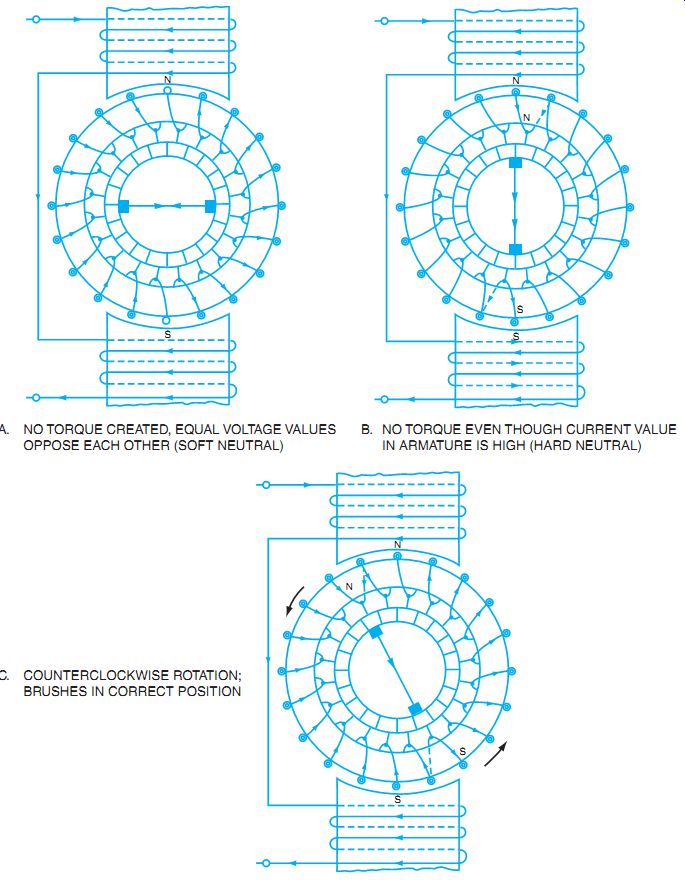
FIG. 4 Repulsion motor operation.
A. NO TORQUE CREATED, EQUAL VOLTAGE VALUES OPPOSE EACH OTHER (SOFT NEUTRAL)
B. NO TORQUE EVEN THOUGH CURRENT VALUE IN ARMATURE IS HIGH (HARD NEUTRAL)
C. COUNTERCLOCKWISE ROTATION; BRUSHES IN CORRECT POSITION
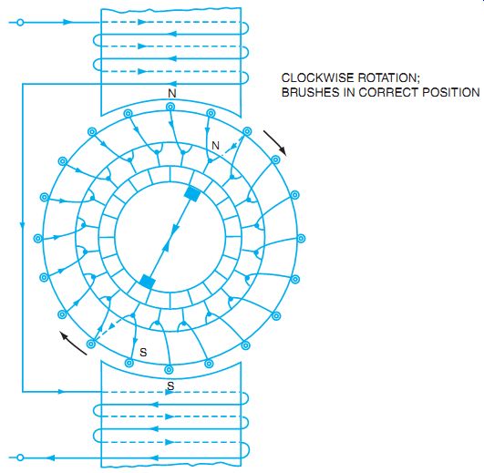
FIG. 5 Reversing the direction of rotation of a repulsion motor.
CLOCKWISE ROTATION; BRUSHES IN CORRECT POSITION
• Centrifugal device.
a. In the brush-lifting type of motor, a centrifugal device lifts the brushes from the commutator surface at 75% of the rated speed. This device consists of governor weights, a short-circuiting necklace, a spring barrel, spring, push rods, brush holders, and brushes. Although high in initial cost, this device does save wear and tear on brushes, and runs quietly. FIG. 6 is an exploded view of the armature, radial commutator, and centrifugal device of the brush-lifting type of repulsion-start, induction-run motor.
b. The brush-riding type of motor also contains a centrifugal device that operates at 75% of the rated speed. This device consists of governor weights, a short- circuiting neck lace, and a spring barrel. The commutator segments are short-circuited by this device, but the brushes and brush holders are not lifted from the commutator surface.
• Commutator. The brush-lifting type of motor has a radial type of commutator (FIG. 6). The brush-riding type of motor has an axial commutator (FIG. 7).
• Brush-holder assembly.
a. The brush-holder assembly for the brush-lifting type of motor is arranged so that the centrifugal device can lift the brush holders and brushes clear of the commutator surface.
b. The brush-holder assembly for the brush-riding type of motor is the same as that of a repulsion motor.
• End shields, bearings, and motor frame. The parts are the same as those of a repulsion motor.
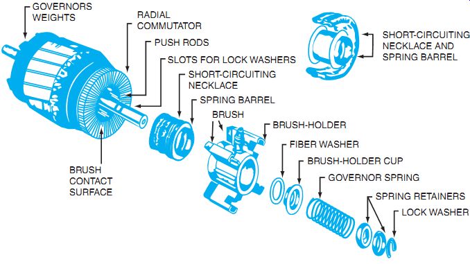
FIG. 6 An exploded view of a radial commutator and centrifugal brush-lifting
device for a repulsion-start, induction-run motor.
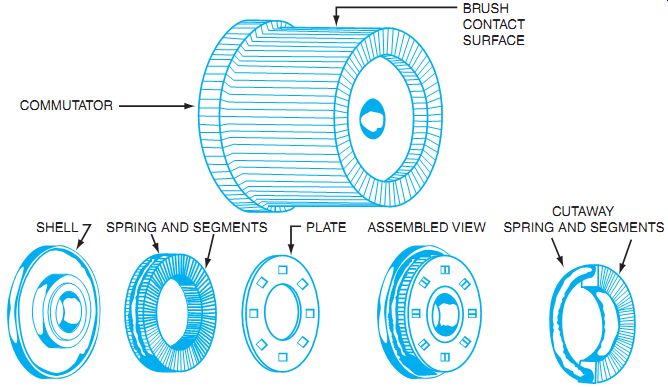
FIG. 7 An exploded view of a short-circuiting device for a brush-riding,
repulsion start, induction-run motor.
Operation of the Centrifugal Mechanism
Refer to FIG. 7 to identify the components of the centrifugal mechanism. The operation of this device consists of the following steps. As the push rods of the centrifugal device move forward, they push the spring barrel forward. This allows the short-circuiting necklace to make contact with the radial commutator bars; thus, all are short-circuited. At the same time, the brush holders and brushes are moved from the commutator surface. As a result, there is no unnecessary wear on the brushes and the commutator surface, and there are no objectionable noises caused by the brushes riding on the radial commutator surface.
The short-circuiting action of the governor mechanism and the commutator segments converts the armature to a form of squirrel-cage rotor, and the motor operates as a single-phase induction motor. In other words, the motor starts as a repulsion motor and runs as an induction motor.
In the brush-riding type of motor, an axial commutator is used. The centrifugal mechanism (FIG. 7) consists of a number of copper segments that are held in place by a spring.
This device is placed next to the commutator. When the rotor reaches 75% of the rated speed, the centrifugal device short-circuits the commutator segments. The motor then continues to operate as an induction motor.
Operation of a Repulsion-Start, Induction-Run Motor
The starting torque is good for either the brush-lifting type or the brush-riding type of repulsion-start, induction-run motor. Furthermore, the speed performance of both types of motors is very good because they operate as single-phase induction motors.
Because of the excellent starting and running characteristics for both types of repulsion start, induction-run motors, they have been used for a variety of industrial applications, including commercial refrigerators, compressors, and pumps.
The direction of rotation for a repulsion-start, induction-run motor is changed in the same manner as that for a repulsion motor, that is, by shifting the brushes past the stator pole center 15 electrical degrees. The symbol in FIG. 8 represents both a repulsion-start, induction-run motor and a repulsion motor.
Many repulsion-start, induction-run motors are designed to operate on 115 volts or 230 volts. These dual-voltage motors contain two stator windings. For 115-volt operation, the stator windings are connected in parallel; for 230-volt operation, the stator windings are connected in series. The diagram in FIG. 9 represents a dual-voltage, repulsion-start, induction-run motor. The connection table shows how the leads of the motor are connected for either 115-volt operation or 230-volt operation. These connections also can be used for dual-voltage repulsion motors.
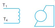
FIG. 8 Schematic diagram symbol of a repulsion-start, induction-run motor
and a repulsion motor.
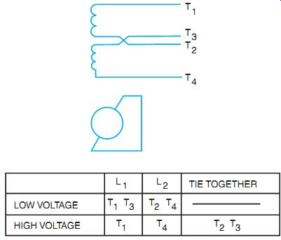
FIG. 9 Schematic diagram of a dual-voltage, repulsion-start, induction-run
motor.
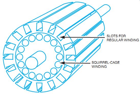
FIG. 10 An armature of a repulsion-induction motor.
REPULSION-INDUCTION MOTOR
The operating characteristics of a repulsion-induction motor are similar to those of the repulsion-start, induction-run motor. However, the repulsion-induction motor has no centrifugal mechanism. It has the same type of armature and commutator as the repulsion motor, but it has a squirrel-cage winding beneath the slots of the armature.
FIG. 10 shows a repulsion-induction motor armature with a squirrel-cage
winding.
One advantage of this type of motor is that it has no centrifugal device requiring maintenance.
The repulsion-induction motor has a very good starting torque because it starts as a repulsion motor. At start-up, the repulsion winding predominates; however, as the motor speed increases, the squirrel-cage winding is used most. The transition from repulsion to induction operation is smooth because no switching device is used. In addition, the repulsion-induction motor has a fairly constant speed regulation from no load to full load because of the squirrel-cage winding. The torque-speed performance of a repulsion-induction motor is similar to that of a DC compound motor.
A repulsion-induction motor can be operated on either 115 volts or 230 volts. The stator winding has two sections connected in parallel for 115-volt operation and in series for 230-volt operation. The markings of the motor terminals and the connection arrangement of the leads are the same as in a repulsion-start, induction-run motor. The symbol in FIG. 8 also represents a repulsion-induction motor (as well as a repulsion-start, induction-run motor and a repulsion motor).
NATIONAL ELECTRICAL CODE REGULATIONS
National Electrical Code requirements for the motor branch-circuit overcurrent protection, motor overcurrent protection, and wire sizes for motor circuits are provided in Article 430 of the Code.
SUMMARY
AC series motors are conduction motors, just like series DC motors. The construction is slightly different because the magnetic field changes affect the inductance of the iron. The principle of operation is the same as that of the series DC motor. The armature keeps the same magnetic polarity of the rotor, reacting with the same magnetic field of the stator through the process of commutation.
Repulsion motors are available in three basic designs: (1) repulsion motors, (2) repulsion-start, induction-run motors, and (3) repulsion-induction motors. These motors are easy to recognize because they are AC induction motors but use a commutator and brushes. The important point to remember is that the motors have neutral positions of the brush mountings that yield no motor movement. These neutral positions are referred to as hard or soft neutral. The brushes are shifted off soft neutral to give the motor the desired direction of rotation.
QUIZ
A. Completely answer the following questions.
1. a. Describe the basic differences in construction between the concentrated-field and the distributed-field types of universal motors. b. Draw the schematic diagram for each type of motor.
a.
b.
2. What is the function of the compensating winding in a two-field compensated universal motor? _____
3. Describe three methods of controlling the speed of universal motors.
4. Why does a universal motor spark excessively at the commutator if its direction of rotation is reversed?
5. A DC series motor operates unsatisfactorily on AC. What are the primary reasons for this fact?
6. What is a repulsion motor, and how is rotation produced?
7. Name one application of a repulsion motor.
8. Describe the operation of a repulsion-start, induction-run motor.
9. Explain the difference between the brush-lifting type of repulsion-start, induction-run motor and the brush-riding type of repulsion-start, induction-run motor.
10. A 2 hp, 230-volt, 12-ampere, single-phase repulsion-start, induction-run motor is connected directly across the rated line voltage.
a. Determine the overcurrent protection for the branch circuit feeding this motor.
b. Determine the running overcurrent protection for this motor.
12. Describe the construction of a repulsion-induction motor.
13. What is one advantage to the use of the repulsion-induction motor as compared to the repulsion-start, induction-run motor?
14. Explain how the direction of rotation is changed for any one of the three types of single phase repulsion motors covered in this unit.
B. Select the correct answer for each of the following statements, and place the corresponding letter in the space provided.
15. The operation of a DC shunt motor from an AC source is impractical because _
a. too much torque is developed at start-up.
b. the starting current is too high.
c. the shunt field inductance is too high.
d. the shunt field inductance is too low.
16. A series DC motor fails to operate satisfactorily on AC due to _
a. eddy currents and high field voltage drop.
b. excessive heat and low field voltage drop.
c. low reactance of the armature and field.
d. high armature reluctance and low field reactance.
17. The frames of universal motors are made of __
a. rolled steel.
b. cast iron.
c. aluminum.
d. all of the above
18. A compensating winding __
a. increases the reactance in the armature on AC.
b. reduces the reactance in the armature on AC.
c. reduces the reactance in the armature on DC.
d. increases the reactance in the armature on DC.
19. After changing the direction of rotation of a universal motor, the____
a. brushes must be rotated for sparkless commutation.
b. field connections must be shifted.
c. field reactance must be decreased.
d. field reactance must be increased.
20. Insert the correct word or phrase to complete each of the following statements.
a. A repulsion-induction motor has a good ___ and a fairly good ___.
b. A repulsion motor has a high starting torque and its speed rapidly decreases with___.
c. The centrifugal short-circuiting device on a repulsion-start, induction-run motor operates at approximately __ of the rated speed.
d. Both the repulsion-start, induction-run motor and the repulsion-induction motor operate as _ after they have accelerated to rated speed.