AMAZON multi-meters discounts AMAZON oscilloscope discounts
GOALS:
• describe the operations of stepper motors.
• determine two types of Servo motors.
• explain how motion control and feedback are obtained with servo motors.
• explain how braking and regeneration works.
• describe the operation of a simple selsyn system and a differential selsyn system.
• list several advantages of a selsyn system.
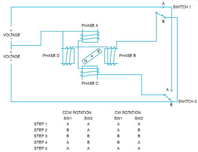
Fig. 1 Stepper motor showing switch position and DC voltage source.
STEPPER MOTORS
Stepper motors are specialized motors that also create incremented steps of motion rather than a smooth unbroken rotation. The basic stepper concept is explained using a permanent magnet on the rotor with two sets of poles, as shown in Fig. 1. As the stator is energized with pulses of DC, the permanent magnet rotor is repelled or attracted to line up with the stator magnetic poles. A stepper controller provides the pulses, as illustrated in Fig. 2.
The electronic controller provides timing and sequencing of the motor, but it operates electronically to provide circuit closure, as shown in Fig. 1. For example, by moving switches 1 and 2 to position A or B, the top poles or the side poles can be reversed. By following the first switch sequence where both switches are set to A, the top and right poles become north magnetic polarity and the rotor aligns between the poles. Step two changes switch 1 to B. If power is left on the top poles, the rotor aligns top to bottom. When switch 1 connects to point B, the rotor again moves, the south rotor pole aligning between the top and left poles.
This results in counterclockwise (CCW) rotation. To reverse the direction of rotation, use the second set of steps. Note that by changing the sequence and length of time the coils are energized, and the direction and speed of the steps are controlled.
The rotor could be one of three different styles: the variable-reluctance rotor, the permanent-magnet (PM) rotor, or a combination of the two-a hybrid rotor. Rather than being simply two magnetic poles, the rotor is many magnetic poles lined up with the teeth on the rotor. The rotor's teeth are spaced so that only one set of teeth remains in perfect alignment with the stator poles at any one time.
By taking the number of times the power must be applied to the stator poles to move one tooth through 360° of mechanical rotation, you can calculate the step angle. For example, if the stator needs 200 pulses of power to move one tooth 360°, then divide 360 by 200 to get 1.8° of motion per step. The motor will move 1.8° per pulse of stator power. Steppers are available step angles of 90°, 45°, 15°, 7.5°, 1.8°, and 0.9°. The resolution of the motor is a measure of how fine the steps are divided. Resolution is determined by dividing 360° by the step angle. The 1.8° step-angle motor takes 200 steps to move around a full revolution, so the resolution is 200. Step angle and resolution are inversely proportional to each other.
The PM rotor was used for the example on step motion control. These PM rotors are used with the four pole pieces to provide either 90° or 45° of step angle. This allows the motors to turn at higher speed, but with less resolution. The poles can be physically larger because there are only four of them; thus, the stator windings can carry higher current. Higher current capability means that more torque is available.
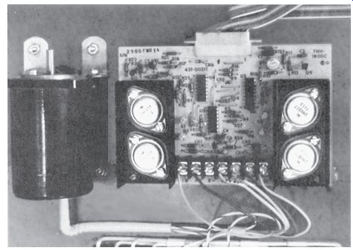
Fig. 2 Stepper motor and associated electronic controller.
SERVO MOTORS
Many manufacturing systems and robotic material handling systems use Servomotors to position controls for fast precision movement. Servo motors are small PM motors that use lightweight armatures to provide quick start and stop operations without a lot of inertia to overcome. See Fig. 3 for a sample of a PM motor with four poles.
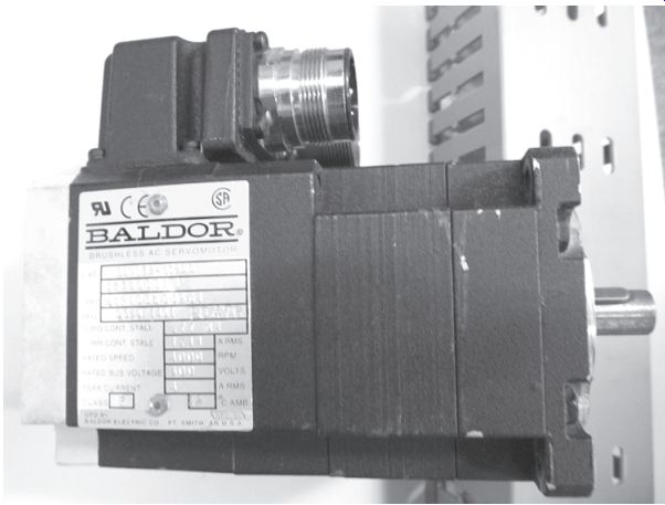
Fig. 3 Servo motor used to produce robot joint movement.
At slow speeds of rotation, the standard PM servomotors have a tendency to create cogging; that is, they tend to ratchet through the rotation rather than have smooth rotation. This is a result of the iron in the armature being magnetized and reacting with the PM on the stator pole pieces.
Servo Motor and Controllers
The two general types of AC servo-motors are considered either synchronous or asynchronous.
Synchronous Servos do not use induction type rotors as in the most common types of AC motors. They do not rely on an AC induction rotor that has current induced into it. Instead they rely on a rotor that is made of PMs. The concept is to make the rotor as light as possible so that the rotor itself has little mass and therefore little inertia to overcome as it starts and stops.
As the stator field is energized, the rotor follows the rotating magnetic field of the stator at the same (synchronous) speed. As the stator field stops, the rotor stops too. With a PM rotor, less heat is produced in the motor because it has no rotor current. Also because no rotor current is needed from the line, the motors are more efficient. To control where the rotor is with respect to the stator, feedback is required to the motor controller. An encoder is typically used and the information is fed back to the controller within one revolution on the synchronous Servo.
Asynchronous Servos rely on induction to supply current and therefore magnetic flux to the rotor. The rotor is like a typical squirrel cage, with efforts to keep it as light as possible to keep inertia low. As in regular induction motors, the rotating field of the stator cuts the rotor conductors and induces current into the rotor, which creates flux in the rotor. This magnetic field is then pushed and pulled around the stator. As with all induction motors, there is slip, as the rotor's poles must fall behind the stator poles. Again, the controller must know the actual position of the rotor for precise speed and position controls.
Servo motors are used for exact speed, torque, and positioning of driven machines.
Because speed is the major parameter, the speed of the rotating magnetic stator field is con trolled. In most cases, this is done by controlling the frequency of the applied AC to the stator. To do this, an electronic controller is used to create variable AC frequency and voltage.
A pulse-width modulation (PWM) system is used to control the desired frequency and the corresponding voltage needed to drive the motor. PWMs are described in section 15. Be sure to check that a particular Servo motor is designed to fit a particular controller and that the motor is designed to work with PWM drives. The torque, or twisting effort of the motor, is also a major parameter. The rated torque is often listed at full speed, at half speed, and at zero speed (stalled). The stall torque is the capability to hold a load in place when there is no rotational speed. This stall point has an associated stall current and often lists the associated rise in temperature as the needed current is applied to hold the load stationary. The winding insulation temperature on the motor is designed to withstand the hot spot temperature of the winding as it holds indefinitely the stall current and the associated torque.
Duty cycles are used as a parameter as to how long and how hard the motor can run without cooling down. The duty cycles are arranged from S1 to S9. S1 is a continuous rating, meaning no rest or "off " time is required. An S3 can run for 4 out of every 10 minutes. An S6 runs 4 minutes at full load and 6 minutes at stalled load. Feedback of speed and position of the rotor is accomplished by use of encoders and resolvers. An incremental encoder is used for basic information (see Fig. 4). The encode signal tells the controller whether the rotor is accelerating, at set speed, or decelerating (see Fig. 5). By counting the number of pulses, the controller can determine how many revolutions the rotor has made since the start command was issued. This system closes the loop between the desired command sent to the motor and the actual rotor response. A variation on the encoder design and reading created a reference pulse for the controller to know where asynchronous Servos rotors are in their real revolutions.
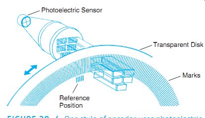
Fig. 4 One style of encoder uses photoelectric sensors and incremental
marks to track motion.
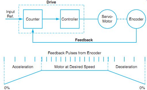
Fig. 5 Pulses are read and interpreted as acceleration, deceleration,
or constant speed.
There is less precision because there has to be one full revolution for the encoder to register the reference mark. As the need for precision increases, more sophisticated techniques are used to keep track of the exact position of the rotor. The controller uses a more complex system for following the rotor movement and keeping track of the total number of revolutions from an initial reference point.
Resolver methods to track the rotor movement can also be used. The resolver uses the technique of a rotating magnet that induces a sine wave into the receiver. The rotor uses two magnetic fields spaced 90° apart. As they pass the receiver, they each induce a sine wave. By comparing the two waveforms, the controller calculates the speed, direction, and position of the rotor (see Fig. 6).
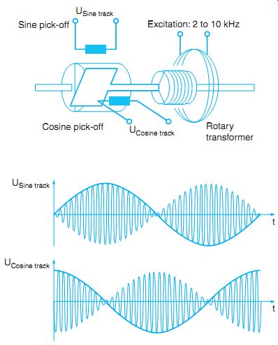
Fig. 6 A resolver uses a magnetic field to track motion.
Braking and Regeneration
Motors have four general conditions: start and accelerate, run at set speed, decelerating to stop, and stopped or stalled. Decelerating or slowing down can be gradual with removal of power and coasting to a stop, or the deceleration can be controlled and finally a brake applied to hold the rotor position. The process of slowing the motor with a mechanical load attached has the effect of the load inertia pulling the rotor faster than the rotating magnetic field provides. This overhauling effect is known as negative torque. As the rotor spins past the magnetic field of the stator, the motor becomes a generator, or produces a regenerated voltage. This voltage is actually generated back into the stator as a reverse voltage from the applied voltage. This regeneration can be used to slow the motor, just as a generator would slow down as it does more electrical work. If the electrical energy is fed back to the controller, the voltage could cause damage to the DC converter section of the controller. This is the front end of the controller that converts AC to DC for use by the PWM inverter section. By installing a braking resistor across the converter DC bus, the excess energy can be dissipated by closing the circuit to the resistor, in this case through an insulated gate bipolar transistor (IGBT), as shown in Fig. 7.
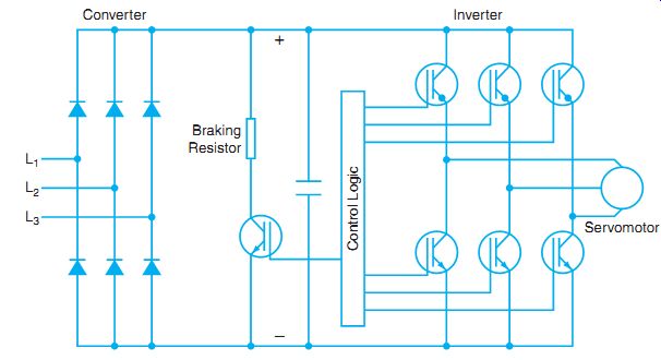
Fig. 7 A braking resistor can be used to dissipate energy during braking.
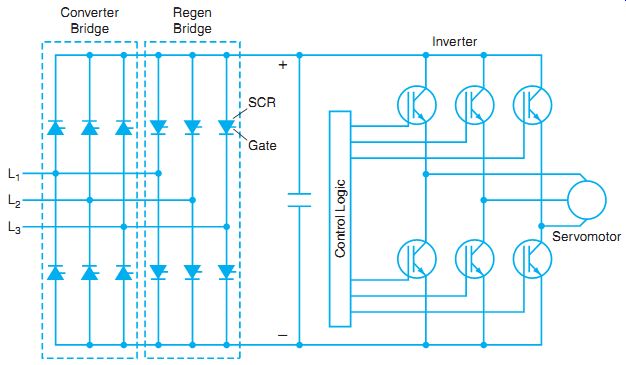
Fig. 8 Regenerated power is returned to power source.
Another system allows the regenerated power to be returned to the power source. This method uses an SCR rectifier bridge to rectify the AC supply for the DC bus. A separate SCR rectifier bridge is mounted in reverse to the first and is turned on when there is regeneration.
The regenerated power is now returned directly to the power source (see Fig. 8).
Servo Disc motor is a motor with a different design. The rotor is a nonconductive disc that has layers of copper "printed" on it, which leads to another name for the same motor: printed circuit motor. (See Fig. 9.) The PMs that form the stator are mounted on either side of the disc rotor. The conductors on the rotor are brought out to one side of the disc, and external connections are made through small brushes that ride on the disc. Because the conductors are under a PM pole piece, the current in the rotor creates a magnetic flux that reacts with the pole piece to create torque. The number of pole pieces and the corresponding conductors multiplies this twisting torque. The turning effort is smooth at all speeds because there is no iron in the armature to create the cogging effect as seen in traditional PM motors.
Also, because of the thin, not steel rotor, the Servo Disc motor has very fast acceleration. It can accelerate to 3000 RPM in about 60° of rotation, or 1/6 of one revolution. The same feature of the rotor allows it to stop and reverse very quickly as well. As with other DC motors, the current through the rotor controls the speed. The rotor resistance is, of course, a fixed value, so the voltage control to the armature is varied to control speed, and voltage is reversed to provide reverse direction.
As with the AC electronic controls, PWM is used to control both the voltage level and the frequency. The frequency is maintained near 20 kHz of pulsating DC. By controlling the "on" time of the pulse, the voltage is varied, and therefore the speed is controlled. By controlling the direction of the DC polarity, the direction is controlled. See Fig. 10 for a photo of a Servo Disc motor.
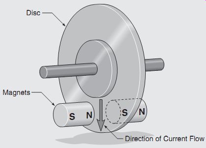
Fig. 9 Basic construction of a Servo-Disc motor.
SELSYN MOTORS
The word selsyn is an abbreviation of the term self-synchronous. Selsyn units are special AC motors used primarily in applications requiring remote control. Small selsyn units transmit meter readings or values of various types of electrical and physical quantities to distant points.
For example, the captain on the bridge of a ship may adjust the course and speed of the ship; at the same moment, the course and speed changes are transmitted to the engine room by selsyn units. On the engine telegraph system, mechanical positioning of a control transmits electrical angular information to a receiving unit. Similarly, readings of mechanical and electrical conditions in other parts of the ship can be recorded on the bridge by selsyn units. These units are also referred to as synchros, and are known by various trade names.
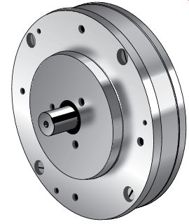
Fig. 10 The DC Servo-Disc motor can be constructed with small, thin cases.
STANDARD SELSYN SYSTEM
A selsyn system consists of two three-phase induction motors. The normally stationary rotors of these induction motors are interconnected so that a manual shift in the rotor position of one machine is accompanied by an electrical rotor shift in the other machine in the same direction and of the same angular displacement as the first unit.
Fig. 11 shows a simple selsyn system for which the units at the transmitter and receiver are identical. The rotors of these units are two pole and must be excited from the same AC source. Three leads between the transmitter and the receiver units connect the three-phase stator windings to each other. The rotor of each machine is called the primary, and the three phase stator winding of each machine is called the secondary. A rotor for a typical selsyn unit is shown in Fig. 12.
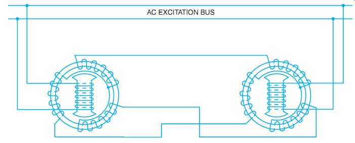
Fig. 11 Diagram of selsyn motors showing interconnected stator and rotor
windings connected to excitation source.
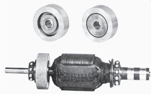
Fig. 12 Wound rotor with oscillation damper and slip rings for selsyn
units.
When the primary excitation circuit is closed, an AC voltage is impressed on the transmitter and receiver primaries. If both rotors are in the same position with respect to their stators, no movement occurs. If the rotors are not in the same relative position, the freely movable receiver rotor will turn to assume the same position as the transmitter rotor. If the transmitter rotor is turned, either manually or mechanically, the receiver rotor will follow at the same speed and in the same direction.
The self-synchronous alignment of the rotors is the result of voltages induced in the secondary windings. Both rotors induce voltages into the three windings of their stators. These voltages vary with the position of the rotors. If the two rotors are in the same relative position, the voltages induced in the transmitter and receiver secondaries are equal and opposite. In this condition, current does not exist in any part of the secondary circuit.
If the transmitter rotor is moved to another position, the induced voltages of the secondaries are no longer equal and opposite, and currents are present in the windings. These currents establish a torque that tends to return the receiver rotor to a synchronous position. Because the receiver rotor is free to move, it makes the adjustment. Any movement of the transmitter rotor is accompanied immediately by an identical movement of the receiver rotor.
DIFFERENTIAL SELSYN SYSTEM
Fig. 13 shows a diagram of the connections of a differential selsyn system consisting of a transmitter, a receiver, and a differential unit. This system produces an angular indication of the receiver. The indication is either the sum or difference of the angles existing at the transmitter and differential selsyns. If two selsyn generators, connected through a differential selsyn, are moved manually to different angles, the differential selsyn indicates the sum or difference of their angles.
A differential selsyn has a primary winding with three terminals. Otherwise, it closely resembles a standard selsyn unit. The three primary leads of the differential selsyn are brought out to collector rings. The unit has the appearance of a miniature wound-rotor, three-phase induction motor. The unit, however, normally operates as a single-phase transformer.
The voltage distribution in the primary winding of the differential selsyn is the same as that in the secondary winding of the selsyn exciter. If any one of the units is fixed in position and a second unit is displaced by a given angle, then the third unit (which is free to rotate) turns through the same angle. The direction of rotation can be reversed by interchanging any pair of leads on either the rotor or stator winding of the differential selsyn.
If any two of the selsyns are rotated simultaneously, the third selsyn turns through an angle equal to the algebraic sum of the movements of the two selsyns. The algebraic sign of this value depends on the rotation direction of the rotors of the two selsyns, as well as the phase rotation of their windings.
The excitation current of the differential selsyn is supplied through connections to one or both of the standard selsyns to which the differential selsyn is connected. In general, the excitation current is supplied to the primary winding only. In this case, the selsyn connected to the differential stator supplies this current and must be able to carry the extra load without overheating. A particular type of selsyn, known as an exciter selsyn, is used to supply the current.
The exciter selsyn can function in the system either as a transmitter or a receiver.
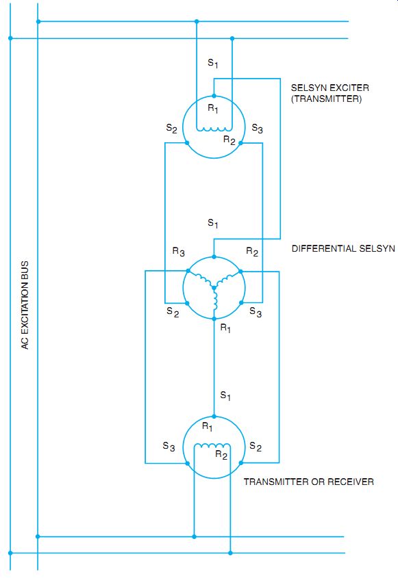
Fig. 13 A schematic diagram of differential selsyn connections.
ADVANTAGES OF SELSYN UNITS
Selsyn units are compact and rugged, and provide accurate and very reliable readings. Because of the comparatively high torque of the selsyn unit, the indicating pointer does not oscillate as it swings into position. Internal mechanical dampers are used in selsyn receivers to prevent oscillation during the synchronizing procedure and to reduce any tendency of the receiver to operate as a rotor.
The operation of the receiver is smooth and continuous and is in agreement with the transmitter. In addition, the response of the receiver to changes in position at the transmitter is very rapid.
In the event of a power failure, the indicator of the receiver resets automatically with the transmitter when power is received. Calibration and time-consuming checks are unnecessary.
A number of advantages are offered by selsyn systems:
• The indicators are small and compact and can be located where needed.
• The simple installation requires running a few wires and bolting the selsyn units in place.
• Selsyn units can be used to indicate either angular or linear movement.
• Selsyn units control the motion of a device at a distant point by controlling its actuating mechanism.
• One transmitter may be used to operate several receivers simultaneously at several distant points.
SUMMARY
Stepper motors are used for incremental motion control. They produce motion in steps as a magnetic field moves as determined by a stepper controller. Servo motors also provide precision motion control and quick start and stop operation as needed in positioning controls. Two styles of servos are synchronous and asynchronous motors. Feed back as to position, speed and rotational direction can be acquired through different techniques. Braking and holding of motors is essential to positioning motors to move and hold loads as directed by the controller.
The selsyn system is also referred to as a synchro system. The self-synchronous system allows one rotor to act as a transmitter and the other to act as a receiver to either directly follow the sender, or follow at a prescribed offset angle.
QUIZ
Select the correct answer for each of the following statements, and place the corresponding letter in the space provided.
1. Selsyn transmitters and receivers resemble ____
a. repulsion-induction motors.
b. three-phase, two-pole induction motors.
c. three-phase, four-pole induction motors.
d. synchronous machines.
2. When the primary excitation circuit is closed, AC voltage is impressed on the____.
a. transmitter and receiver primaries.
b. transmitter rotor and the transmitter stator windings.
c. transmitter rotor and the receiver stator windings.
d. stator windings of both instruments.
3. A differential selsyn unit differs from a selsyn transmitter or receiver in that it requires____
a. three-phase power for excitation.
b. an AC line connection to the stator winding.
c. DC on the rotor winding.
d. three connections to the rotor winding.
4. If the rotors of the two selsyn units in a selsyn-indicating system are in exactly corresponding positions, the current in the secondary winding is ____.
a. within quadrature with the primary current.
b. in phase with the primary current.
c. zero.
d. less than the normal primary current.
5. Selsyn units are also referred to as ____
a. synchros.
b. induction motors.
c. wound-rotor motors.
d. all of the above
6. The stator of the transmitter is directly connected to the stator of the receiver unit when a differential is not used. ____
a. true
b. false
7. In the transmitter and receiver system, the AC excitation is applied to the ____.
a. stator winding.
b. stator and the rotor windings.
c. rotor winding only.
d. none of the above
8. Cite several advantages of a selsyn system._
9. The purpose of a stepper motor is to
a. provide incremental steps of motion.
b. provide steps of rotation that are imperceptible.
c. create a vertical motion rather than a rotational motion.
d. create a stair-step output from the controller.
10. A synchronous Servos uses
a. wound rotors for rotor construction.
b. PM rotors.
c. shaded pole rotors.
d. squirrel-cage rotors.
11. Asynchronous Servos use
a. wound rotors for rotor construction.
b. PM rotors.
c. shaded pole rotors.
d. squirrel-cage rotors.
12. When a Servo motor is slowing down, the load inertia sometimes causes the motor to spin faster than desired. This is called:
a. negative torque.
b. over-speed torque.
c. regenerative torque.
d. dynamic braking inertia.