AMAZON multi-meters discounts AMAZON oscilloscope discounts
GOALS:
• describe the basic operation of the following types of induction motors:
• split-phase motor (both single and dual voltage).
• capacitor-start, induction-run motor (both single and dual voltage).
• capacitor-start, capacitor-run motor with one capacitor.
• capacitor-start, capacitor-run motor with two capacitors.
• capacitor-start, capacitor-run motor having an auto transformer with one capacitor.
• compare the motors in the preceding listing with regard to starting torque, speed performance, and power factor at the rated load.
• identify shaded pole motor components and operation.
The two principal types of single-phase induction motors are the split-phase motor and the capacitor motor. Both types of single-phase induction motors usually have a fractional horsepower rating. The split-phase motor is used to operate such devices as washing machines, small water pumps, oil burners, and other types of small loads not requiring a strong starting torque. The capacitor motor generally is used with devices requiring a strong starting torque, such as refrigerators and compressors. Both types of single-phase induction motors are relatively low in cost, have a rugged construction, and exhibit a good operating performance.
CONSTRUCTION OF A SPLIT-PHASE INDUCTION MOTOR
The split-phase induction motor basically consists of a stator, a rotor, a centrifugal switch located inside the motor, two end shields housing the bearings that support the rotor shaft, and a cast steel frame into which the stator core is pressed. The two end shields are bolted to the cast steel frame. The bearings housed in the end shields keep the rotor centered within the stator so that it will rotate with a minimum of friction and without striking or rubbing the stator core.
The stator for a split-phase motor consists of two windings held in place in the slots of a laminated steel core. The two windings consist of insulated coils distributed and connected to make up two windings spaced 90 electrical degrees apart. One winding is the running winding, and the second winding is the starting winding.
The running winding consists of insulated copper wire placed at the bottom of the stator slots. The wire size in the starting winding is smaller than that of the running winding. These coils are placed on top of the running winding coils in the stator slots nearest the rotor.
Both the starting and running windings are connected in parallel to the single-phase line when the motor is started. After the motor accelerates to a speed equal to approximately two thirds to three-quarters of the rated speed, the starting winding is disconnected automatically from the line by means of a centrifugal switch.
The rotor for the split-phase motor has the same construction as that of a three-phase AC induction motor; that is, the rotor consists of a cylindrical core assembled from steel laminations. Copper bars are mounted near the surface of the rotor. The bars are brazed or welded to two copper end rings. In some motors, the rotor is a one-piece cast aluminum unit.
FIG. 1 shows a typical squirrel-cage rotor for a single-phase induction motor. This type of rotor requires little maintenance because there are no windings, brushes, slip rings, or commutators. Note in the figure that the rotor fan is part of the squirrel-cage rotor assembly.
These rotor fans maintain air circulation through the motor to prevent a large increase in the temperature of the windings.
The centrifugal switch is mounted inside the motor. The centrifugal switch disconnects the starting winding after the rotor reaches a predetermined speed, usually two-thirds to three quarters of the rated speed. The switch consists of a stationary part and a rotating part. The stationary part is mounted on one of the end shields and has two contacts that act like a single pole, single-throw switch. The rotating part of the centrifugal switch is mounted on the rotor.
A simple diagram of the operation of a centrifugal switch is shown in FIG. 2. When the rotor is at a standstill, the pressure of the spring on the fiber ring of the rotating part keeps the contacts closed. When the rotor reaches approximately three-quarters of its rated speed, the centrifugal action of the rotor causes the spring to release its pressure on the fiber ring and the contacts to open. As a result, the starting winding circuit is disconnected from the line.
FIG. 3 shows a typical centrifugal switch used with split-phase induction motors.
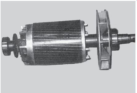
FIG. 1 Cast aluminum squirrel-cage rotor.
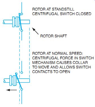
FIG. 2 The operation of a centrifugal switch. ROTOR AT STANDSTILL CENTRIFUGAL
SWITCH CLOSED ROTOR AT NORMAL SPEED:
CENTRIFUGAL FORCE IN SWITCH MECHANISM CAUSES COLLAR TO MOVE AND ALLOWS SWITCH CONTACTS TO OPEN ROTOR SHAFT
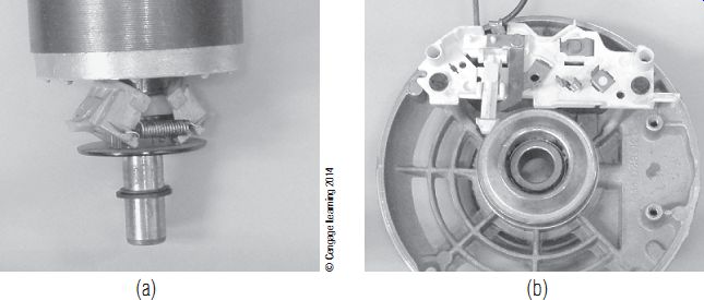
FIG. 3 (A) Centrifugal switch weight mechanism. (B) Stationary part of
centrifugal switch.
Principle of Operation
When the circuit to the split-phase induction motor is closed, both the starting and running windings are energized in parallel. Because the running winding consists of a relatively large size of wire, its resistance is low. Recall that the running winding is placed at the bottom of the slots of the stator core. As a result, the inductive reactance of this winding is comparatively high due to the mass of iron surrounding it. Because the running winding has a low resistance and a high inductive reactance, the current of the running winding lags behind the voltage approximately 90 electrical degrees.
The starting winding consists of a smaller size of wire; therefore, its resistance is high. Because the winding is placed near the top of the stator slots, the mass of iron surrounding it is comparatively small and the inductive reactance is low. Therefore, the starting winding has a high resistance and a low inductive reactance. As a result, the current of the starting winding is nearly in phase with the voltage.
The two windings create the split in the single phase of incoming voltage by the way the current reacts to the two windings (see FIG. 4). Note that the phase split between the currents in the starting winding and the running winding is not the ideal 90°, but the effect is the same as splitting the magnetic effects of the coils to produce the rotating magnetic field needed to get the rotor spinning. After the starting winding is disconnected, the rotor continues to spin because of the pulsating magnetic field of the running winding and the momentum of the spinning rotor and load.
The current of the running winding lags the current of the starting winding by approximately 30 electrical degrees. These two currents, spaced 30 electrical degrees apart, pass through these windings, and a rotating magnetic field is developed. This field travels around the inside of the stator core. The speed of the magnetic field is determined using the same procedure given for a three-phase induction motor.
If a split-phase induction motor has four poles on the stator windings and is connected to a single-phase, 60-Hz source, the synchronous speed of the revolving field is:
Synchronous RPM = 120 * ƒ 4
RPM = 120 * 60 4
RPM = 1800
f _ Frequency in hertz
As the rotating stator field travels at the synchronous speed, it cuts the copper bars of the rotor and induces voltages in the bars of the squirrel-cage winding. These induced voltages set up currents in the rotor bars. As a result, a rotor field is created that reacts with the stator field to develop the torque that causes the rotor to turn.
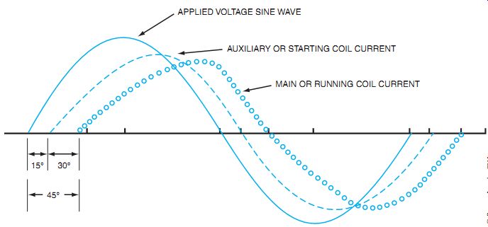
FIG. 4 Sinewaves of split-phase motor voltage and current characteristics.
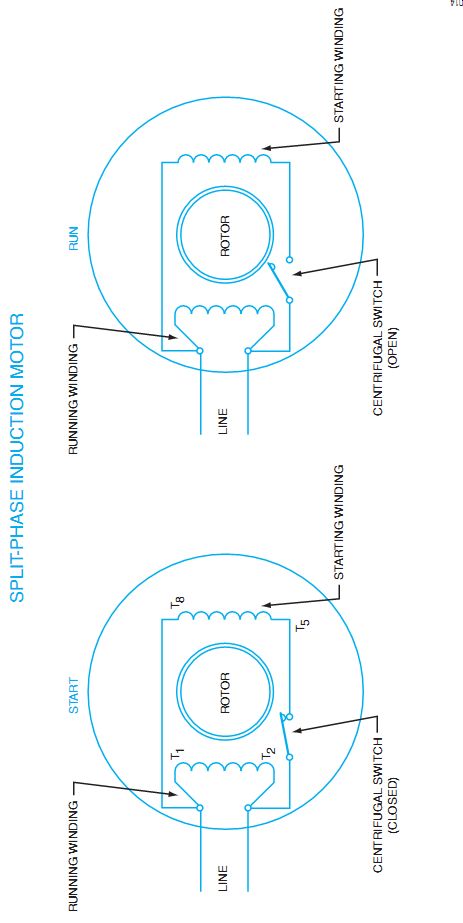
FIG. 5
Connections of the centrifugal switch at start and at run. SPLIT-PHASE INDUCTION
MOTOR:
THE CENTRIFUGAL SWITCH OPENS AT APPROXIMATELY 75% OF RATED SPEED.
THE STARTING WINDING HAS HIGH RESISTANCE AND LOW INDUCTIVE REACTANCE.
THE RUNNING WINDING HAS LOW RESISTANCE AND HIGH INDUCTIVE REACTANCE.
(PRODUCES 458 TO 608 PHASE ANGLE FOR STARTING TORQUE.)
As the rotor accelerates to the rated speed, the centrifugal switch disconnects the starting winding from the line. The motor then continues to operate using only the running winding.
FIG. 5 illustrates the connections of the centrifugal switch at the instant the motor starts (switch closed) and when the motor reaches its normal running speed (switch open).
A split-phase motor must have both the starting and running windings energized when the motor is started. The motor resembles a two-phase induction motor in which the currents of these two windings are approximately 90 electrical degrees out of phase. The voltage source, however, is single phase; therefore, the motor is called a split-phase motor because it starts like a two-phase motor from a split single-phase line. After the motor accelerates to a value near its rated speed, it operates on the running winding as a single-phase induction motor.
If the centrifugal switch contacts fail to close when the motor stops, then the starting winding circuit is still open. When the motor circuit is re-energized, the motor will not start.
The motor must have both the starting and running windings energized at the instant the motor circuit is closed to create the necessary starting torque. If the motor does not start but simply gives a low humming sound, then the starting winding circuit is open. Either the centrifugal switch contacts are not closed, or there is a break in the coils of the starting windings. This is an unsafe condition. The running winding will draw excessive current and, therefore, the motor must be removed from the line supply.
If the mechanical load is too great when a split-phase motor is started, or if the terminal voltage applied to the motor is low, then the motor may fail to reach the speed required to operate the centrifugal switch.
The starting winding is designed to operate at-line voltage for a period of only 3 or 4 seconds while the motor is accelerating to its rated speed. It is important that the starting winding be disconnected from the line by the centrifugal switch as soon as the motor accelerates to 75% of the rated speed. Operation of the motor on its starting winding for more than 60 seconds may burn the insulation on the winding or cause the winding to burn out.
Some motors do not contain the mechanical type of starting switch. Instead they use a switch external to the motor. There are three general types of external starting switches in use that are external to the motor. These starting winding switches may need to be located remotely from the motor for ease of maintenance or because the switching may create an objectionable arc in a hazardous location. In these cases, a voltage- or current-operated switch may be used for mechanical switching, or solid-state relays may be used for arcless switching.
The voltage-operated switch is shown in FIG. 6. Voltage-operated switches are connected across the starting winding. These switches are used with capacitor-start, single-phase motors, but will be explained here with other starting switches. As the motor power is applied, current is allowed to flow through the normally closed switch to the starting winding and the running winding. The starting winding is a low-impedance load because of the starting capacitor in the circuit. The large inrush current causes a large voltage drop across the series capacitor and little across the motor coil. Very little voltage is dropped across the starting winding, and there fore little voltage is dropped across the coil for the starting switch, which keeps the relay contacts closed. As the rotor begins to spin, the CEMF generated into the starting coil increases, and the coil begins to drop a greater percentage of the line voltage. Now the starter relay coil energizes and opens the contacts, interrupting current to the starting winding. The induced voltage from the spinning rotor is enough to hold the relay contacts open while the motor is spinning.
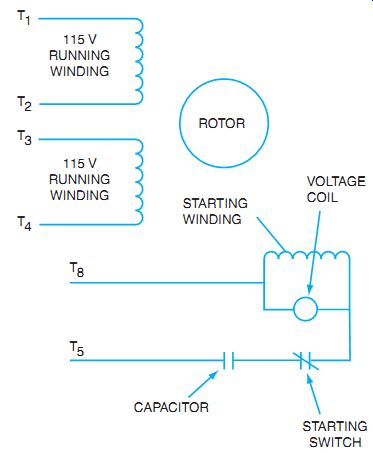
FIG. 6 Single-phase motor using a voltage-operated coil for starting
winding circuit for a capacitor-start motor.
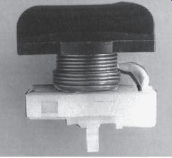
FIG. 7 Current type of starting relay.
A second style of mechanical switch is the current-operated starting switch shown in FIG. 7. The current coil is connected in series with the running winding, as shown in FIG. 8. As power is applied to the single-phase motor, the current inrush to the running winding is relatively large (six to ten times running current). This large inrush current causes the current relay to pull the contacts closed, which are in series with the starting winding. These contacts allow current to flow to the starting winding, and the rotor begins to spin. As the motor increases in speed, the inrush current diminishes and the current coil contacts are allowed to open. The starting winding is now disconnected from the line power, and the motor operates as a normal single-phase motor.
A third type of starting relay is the electronic relay, shown in FIG. 9. This is used effectively for arcless switching of the starting winding. The relay is connected as shown in FIG. 10. The concept is the same as the current-operated relay, but the sensing device is a thermistor. This thermistor is a solid-state device that will react to a change in temperature by increasing its resistance (positive temperature coefficient). Because the thermistor is in series with the starting winding, the current to the starting winding causes the temperature of the thermistor to increase, and the resistance also begins to increase from 3 to 4 ohms up to a few thousand ohms. This has the same effect as opening the switch to the winding. A small amount of current is still flowing through the high resistance to the starting winding. This current does not affect the motor operation, but is needed to keep the thermistor warm and the resistance high. This type of starting switch is sensitive to temperature, and if it is not allowed to cool sufficiently, it may prevent the starting winding from performing normally during starting. Be sure to allow the motor to cool down between successive starts.
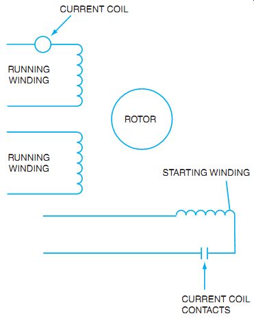
FIG. 8 Single-phase motor with current operated coil for starting winding
circuit.
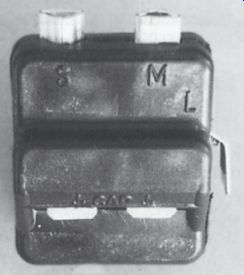
FIG. 9 Solid-state running relay.
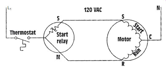
FIG. 10 Solid-state starting relay connection.
To reverse the rotation of the motor, simply interchange the leads of the starting winding (FIG. 11). This causes the direction of the field set up by the stator windings to become reversed. As a result, the direction of rotation is reversed. The direction of rotation of the split phase motor can also be reversed by interchanging the two running winding leads. Normally, the starting winding is used for reversing.
Single-phase motors often have dual-voltage ratings of 115 volts and 230 volts. To obtain these ratings, the running winding consists of two sections. Each section of the winding is rated at 115 volts. One section of the running winding is generally marked T1 and T2, and the other section is marked T3 and T4. If the motor is to be operated on 230 volts, the two 115-volt windings are connected in series across the 230-volt line. If the motor is to be operated on 115 volts, then the two 115-volt windings are connected in parallel across the 115-volt line.
The starting winding usually consists of only one 115-volt winding. The leads of the starting winding are generally marked T5 and T8. If the motor is to be operated on 115 volts, both sections of the running winding are connected in parallel with the starting winding (FIG. 12).
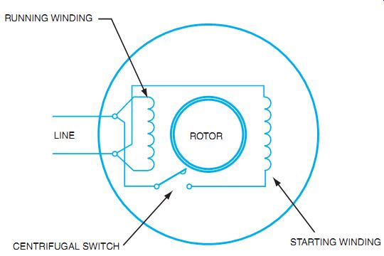
FIG. 11 Reversing direction of rotation on split-phase induction motor
usually means that the connections to the starting winding is reversed.
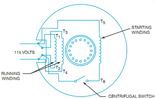
FIG. 12 Dual-voltage motor connected for 115 volts.
For 230-volt operation, the connection jumpers are changed in the terminal box so that the two 115-volt sections of the running winding are connected in series across the 230-volt line (FIG. 13). Note that the 115-volt starting winding is connected in parallel with one section of the running winding. The voltage drop across this section of the running winding is 115 volts, and the voltage across the starting winding is also 115 volts.
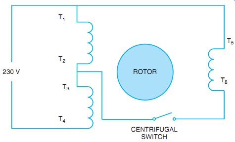
FIG. 13 Dual-voltage motor connected for 230 volts.
Some dual-voltage, split-phase motors have a starting winding with two sections as well as a running winding with two sections. The running winding sections are marked T1 and T2 for one section and T3 and T4 for the other section. One section of the starting winding is marked T5 and T6, and the second section of the starting winding is marked T7 and T8.
The National Electrical Manufacturers Association (NEMA) has color coded the terminal leads. If colors are used, they should be coded as follows: T1, blue; T2, white; T3, orange; T4, yellow; T5, black; and T8, red. If there are leads with T6 and T7, there are no assigned colors from the standard color markings.
FIG. 14 shows the winding arrangement for a dual-voltage motor with two starting windings and two running windings. The correct connections for 115-volt operation and for 230-volt operation are given in the table shown in FIG. 14.
The speed regulation of a split-phase induction motor is very good. It has a speed performance from no load to full load that is similar to that of a three-phase AC induction motor. The percent slip on most fractional horsepower split-phase motors is from 4% to 6%.
The starting torque of the split-phase motor is comparatively poor. The low resistance and high inductive reactance in the running winding circuit and the high resistance and low inductive reactance in the starting winding circuit cause the two current values to be considerably less than 90 electrical degrees apart. The currents of the starting and running windings in many split-phase motors are only 30 electrical degrees out of phase with each other. As a result, the field set up by these currents does not develop a strong starting torque.
CAPACITOR-START, INDUCTION-RUN MOTOR
The construction of a capacitor-start motor is nearly the same as that of a split-phase induction motor. For the capacitor-start motor, however, a capacitor is connected in series with the starting windings. The capacitor is usually mounted in a metal casing on top of the motor. The capacitor may be mounted in any convenient external position on the motor frame and, in some cases, may be mounted inside the motor housing. The capacitor provides a higher starting torque than is obtainable with the standard split-phase motor. In addition, the capacitor limits the starting surge of current to a lower value than is developed by the standard split-phase motor.
The capacitor-start induction motor is used on refrigeration units, compressors, oil burners, and for small machine equipment, as well as for other applications that require a strong starting torque.
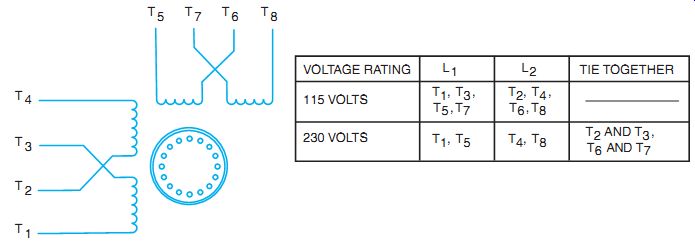
FIG. 14 Winding arrangements for dual-voltage motor with two starting
and two running windings.
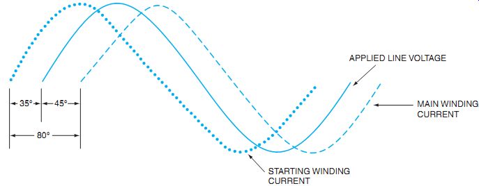
FIG. 15 Sinewave of capacitor-start motor voltage and current characteristics.
Principle of Operation
When the capacitor-start motor is connected for lower voltage and is started, both the running and starting windings are connected in parallel across the line voltage and the centrifugal switch is closed. The starting winding, however, is connected in series with the capacitor. When the motor reaches a value of approximately 75% of its rated speed, the centrifugal switch opens and disconnects the starting winding and the capacitor from the line. The motor then operates as a single-phase induction motor using only the running winding. The capacitor is used to improve the starting torque and does not improve the power factor of the motor.
To produce the necessary starting torque, the revolving magnetic field must have a better split of the single-phase line current. The capacitor added in series with the starting winding causes the current in the starting winding to be shifted to a leading current ahead of the volt age, instead of a lagging current as in the split-phase motor. FIG. 15 illustrates the leading effect caused by the addition of a starting rated capacitor. The current in the starting winding leads the line voltage by approximately 35°, and the current in the running winding lags the line voltage by 45°. This differential creates a split of 80°, nearing the optimum of 90 electrical degrees. This creates a better orientation of the magnetic fields of the stator and therefore creates more torque than a similarly sized split-phase motor.
Defective capacitors are a frequent cause of malfunctions in capacitor-start, induction-run motors. Some capacitor failures that can occur are listed here:
• The capacitor may short itself out, as evidenced by a lower starting torque.
• The capacitor may be "opened," in which case the starting winding circuits will be open, causing the motor to fail to start.
• The capacitor may short-circuit and cause the fuse protection for the branch motor circuit to blow. If the fuse ratings are high and do not interrupt the power supply to the motor soon enough, the starting winding may burn out.
• Starting capacitors can short-circuit if the motor is turned on and off many times in a short period of time. To prevent capacitor failures, many motor manufacturers recommend that a capacitor-start motor be started no more than 20 times per hour. Therefore, this type of motor is used only in applications where there are relatively few starts in a short time period.
The speed performance of a capacitor-start motor is very good. The change in percent slip from a no-load condition to full load is from 4% to 6%. The speed performance then is the same as that of a standard split-phase motor.
The leads of the starting winding circuit are interchanged to reverse the direction of rotation of a capacitor-start motor. As a result, the direction of rotation of the magnetic field developed by stator windings reverses in the stator core, and the rotation of the rotor is reversed (see FIG. 16 for reversing lead connections).
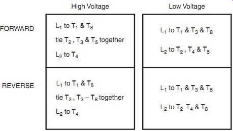
FIG. 16 Chart for two running windings and one starting winding.
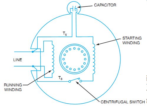
FIG. 17 Connections for a capacitor-start induction motor.
FIG. 17 shows a diagram of the circuit connections of a capacitor-start motor before the starting winding leads are interchanged to reverse the direction of rotation of the rotor. The diagram in FIG. 18 shows the circuit connections of the motor after the starting winding leads are interchanged to reverse the direction of rotation.
A second method of changing the direction of rotation of a capacitor-start motor is to interchange the two running winding leads. However, this method is seldom used.
Capacitor-start, induction-run motors often have dual-voltage ratings of 115 volts and 230 volts. The connections for a capacitor-start motor are the same as those for split-phase induction motors, in that the starting winding is connected across half of the series running winding.
CAPACITOR-START, CAPACITOR-RUN MOTOR OR TWO-VALUE CAPACITOR MOTOR
The capacitor-start, capacitor-run motor is similar to the capacitor-start, induction-run motor, except that the starting winding and capacitor are connected in the circuit at all times. This motor has a very good starting torque. The power factor at the rated load is nearly 100%, or unity, because that a capacitor is used in the motor at all times.
This type of motor can have several different designs. One type of capacitor-start, capacitor-run motor has two stator windings that are spaced 90 electrical degrees apart. The main or running winding is connected directly across the rated line voltage. A capacitor is connected in series with the starting winding, and this series combination is also connected across the rated line voltage. A centrifugal switch is not used, because the starting winding is energized through the entire operating period of the motor.
FIG. 19 illustrates the internal connections for a capacitor-start, capacitor-run motor using one value of capacitance.
To reverse the rotation of this motor, the lead connections of the starting winding must be interchanged. This type of capacitor-start, capacitor-run motor is quiet in operation and is used on air compressors, fans, and small woodworking and metalworking machines.
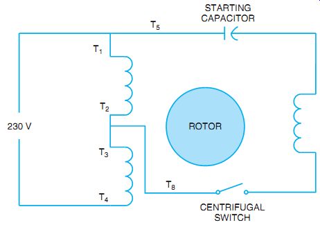
FIG. 18 Connections for reversing a capacitor-start, induction-run motor.
A second type of capacitor-start, capacitor-run motor has two capacitors. FIG. 20 shows a diagram of the internal connections of the motor. At the instant the motor is started, the two capacitors are in parallel. When the motor reaches 75% of the rated speed, the centrifugal switch disconnects the larger capacity capacitor. The motor then operates with the smaller capacitor only connected in series with the starting winding.
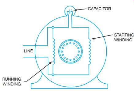
FIG. 19 Connections for a capacitor-start, capacitor-run motor.
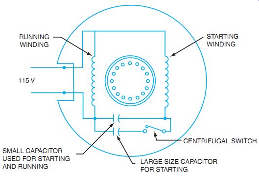
FIG. 20 Connections for a capacitor-start, capacitor-run motor.
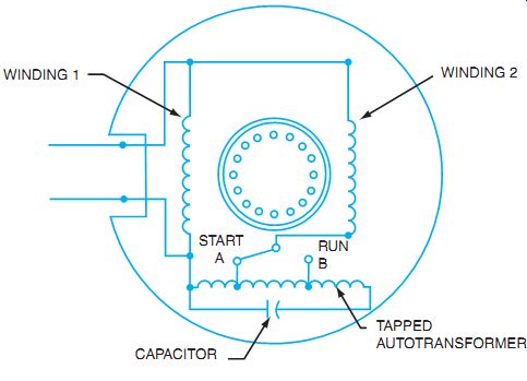
FIG. 21 Connections for a capacitor-start, capacitor-run motor with autotransformer.
This type of motor has a very good starting torque, good speed regulation, and a power factor of nearly 100% at rated load. Applications for this type of motor include furnace stokers, refrigerator units, and compressors.
A third type of capacitor-start, capacitor-run motor has an autotransformer with one capacitor. This motor has a high starting torque and a high operating power factor.
FIG. 21 shows a diagram of the internal connections for this motor. When the motor is started, the centrifugal switch connects winding 2 to point A on the tapped autotransformer.
As the capacitor is connected across the maximum transformer turns, it receives maximum voltage output on start. The capacitor thus is connected across a value of approximately 500 volts. As a result, there is a high value of leading current in winding 2, and a strong starting torque is developed.
When the motor reaches approximately 75% of the rated speed, the centrifugal switch disconnects the starting winding from point A and reconnects this winding to point B on the autotransformer. Less voltage is applied to the capacitor, but the motor operates with both windings energized. Thus, the capacitor maintains a power factor near unity at the rated load.
The starting torque of this motor is very good, and the speed regulation is satisfactory.
Applications requiring these characteristics include large refrigerators and compressors.
A permanent-split capacitor motor is shown in FIG. 22. In this type of motor, a low microfarad, oil-filled capacitor is connected in series with one of the identical coil windings.
FIG. 22 Permanent-split capacitor motor with forward and reverse switches
shown.
By placing a capacitor in series with one winding, the current in that winding leads the cur rent in the other winding, causing a split in the magnetic fields and causing the motor to rotate from the field with the capacitor toward the field without the capacitor. This motor is used for low torque requirements that may require frequent reversing. By simply closing one switch or the other, the capacitor will be in series with different windings, thus reversing the direction of motor rotation.
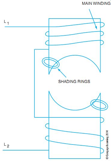
FIG. 23 Schematic of shaded pole motor.
SHADED POLE MOTORS
Shaded pole motors are among the simplest and cheapest motors to construct. The principle of operation uses the effects of induction not only into the squirrel-cage rotor, but also into parts of the stator that create a rotating magnetic field from a single phase of input voltage. These motors are typically fractional horsepower ratings and are used in applications that do not require a great deal of starting torque.
In a simple unidirectional motor, a ring (shading ring) of solid conductor is short- circuited and embedded in one side of a stator winding (see FIG. 23 and FIG. 24).
As the voltage is applied to the top and bottom coils, the shading coil has voltage induced into it. Lenz's law states that the effect of induction always opposes the cause of induction. Therefore, the magnetic field developed by the shading ring as current flows through its shorted winding opposes the main flux. This causes the main magnetic field to be shifted away from the shading ring.
As the applied voltage waveform begins to decrease from its peak value, the magnetic lines of force also decrease. The effect on the shading ring is the opposite. As main current flow decreases, the magnetic effect of the shading ring tends to keep the same polarity as the main pole but increases in strength. This causes the stator pole to move from the main (unshaded) pole toward the shaded pole (see FIG. 25).
Position 1
Top of stator: Main coil magnetic polarity is north pole. Shading ring opposes main with a South polarity.
(Use FIG. 23 as reference.)
Position 2
Top of stator: Main pole is less strong North polarity. Shading ring polarity is zero, so the stator pole moves toward the shading ring.
Position 3
Top of stator: Main pole polarity is less strong North pole.
Shaded pole is stronger North polarity. Stator pole moves more toward the shaded pole.
Position 4
Top of stator: Main pole has no current and no flux. Shaded pole has stronger North polarity, so stator pole moves toward the shaded pole.
This produces a counterclockwise rotation of north pole flux.
To reverse the direction of rotation on shaded pole motors, the relationship between the shading ring and the pole face must be reversed, as the field always moves from the unshaded to the shaded portion of the stator pole. Another set of shading rings on the opposite side may be shorted.
A reversible shaded pole motor has two sets of shading rings. When one set is shorted, the other set is open.
Controlling the speed of shaded pole motors is easy. Either alter the voltage that is applied to the stator winding to produce less voltage per turn on the winding, or change the number of turns by using tapped windings and maintaining the same applied voltage. Either method changes the voltage per turn on the motor. Less voltage per turn means less flux, more slip, and a slower speed under load.
Shaded pole motors are typically used for fans where the blades are directly mounted to the rotor shaft and the air passes over the motor. These fans require little starting torque, and the air over the motor helps keep it cool. If these motors run hot or are in a high vibration area, the shading rings (which are soldered rings of conductors) can open up and cause the motor to fail.
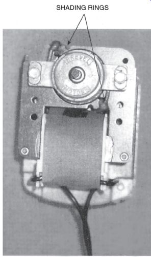
FIG. 24 Photo of one style of shaded pole motor.
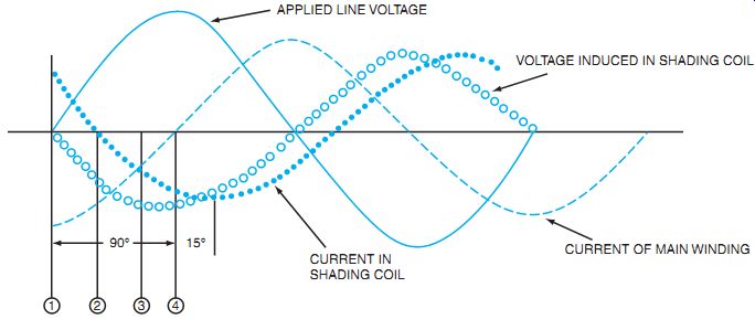
FIG. 25 Shaded pole motor voltage and current waveforms: line voltage,
main coil current, and induced shading coil waveforms.
SUMMARY
The single-phase induction motor is one of the most used residential and light commercial motors. Each application dictates the correct motor style to use. All these motors use the concept of taking one phase, or one sinewave, and shifting the effects of the currents through the coils to create a moving magnetic field. The split-phase and capacitor-start motors use a starting switch to disconnect the starting windings from the line after the motor is up to running speed.
Two-capacitor motors use multiple capacitors or variations of two-value capacitors to create a starting and a running circuit. All NEC regulations that apply to three-phase motors apply to single-phase motors. Many exceptions apply only to small-horsepower motors.
QUIZ
1. List the essential parts of a split-phase induction motor.
2. What happens if the centrifugal switch contacts fail to reclose when the motor stops?
3. Explain how the direction of rotation of a split-phase induction motor is reversed.
4. A split-phase induction motor has a dual-voltage rating of 115/230 volts. The motor has two running windings, each of which is rated at 115 volts, and one starting winding rated at 115 volts. Draw a schematic diagram of this split-phase induction motor connected for a 230-volt operation.
5. Draw a schematic connection diagram of the split-phase induction motor in question 4, connected for a 115-volt operation.
6. A split-phase induction motor has a dual-voltage rating of 115/230 volts. The motor has two running windings, each of which is rated at 115 volts, and one starting winding rated at 115 volts. Draw a schematic diagram of this split-phase induction motor connected for a 230-volt operation.
7. What is the primary difference between a split-phase induction motor and a capacitor start, induction-run motor?
8. If the centrifugal switch fails to open as a split-phase motor accelerates to its rated speed, what happens to the starting winding?
9. Describe one limitation of a capacitor-start, induction-run motor.
10. Insert the correct word or phrase to complete each of the following statements.
a. The capacitor used with a capacitor-start, induction-run motor is used only to improve the .
b. A capacitor-start, induction-run motor has a better starting torque than the ____.
11. Shaded pole motors are ____
a. high-torque motors.
b. low percent, speed-regulation motors.
c. used for large horsepower loads.
d. used for low-torque, low-horsepower loads.