AMAZON multi-meters discounts AMAZON oscilloscope discounts
GOALS:
• determine the operating characteristics of an energy-efficient motor.
• select the proper efficiency points for motors operating at reduced frequencies.
• determine when to use inverter duty motors.
• select integrated motor and controller applications.
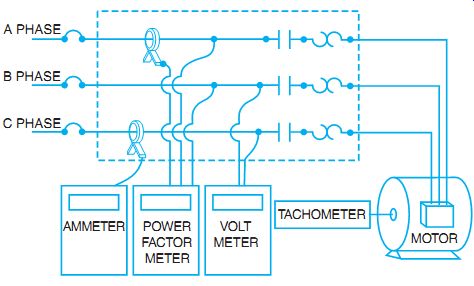
FIG. 1 Power measurement for input to motor.
Standard motor efficiency is calculated by the simple formula of watts output of the motor divided by watts input. Watts output is calculated by determining the mechanical horsepower output and multiplying by 746 watts. Each output horsepower of mechanical energy is equal to 746 watts of electrical energy. The input wattage is measured by an electrical wattmeter, either single phase or three phase, or it is calculated by making current and voltage measurements and power factor measurements (see FIG. 1).
The following formulas provide the input watts to an AC motor.
For single-phase motors, use the formula:
Watts input = line volts × line current × % power factor
For three-phase motors, use the formula:
Watts input = line volts × line current × 1.73 × % power factor
Calculating the output power is sometimes difficult. Horsepower is a function of the motor torque, the speed of the shaft, and the amount of time the motor operates. This means that the motor can move a weight (measured in pounds) a distance (measured in feet) over time (measured in minutes). Originally, a single horsepower was calculated as the amount of effort required to move 33,000 pounds 1 ft in 1 minute. In other words 1 hp = 33,000 ft-lbs/min.
To measure the output, the force on the shaft (ft-lbs) and the RPM (how far a weight at some distance from the center of the shaft would spin in one minute) must be measured. If the motor can be connected to a test device, called a dynamometer, the output horsepower can be directly measured. If the motor can be connected to a device called a prony brake, the torque can be calculated. The torque in foot-pounds is then used in the horsepower formula: hp = 2 × p × torque × RPM / 33,000. If the motor is connected to a driven load, horsepower measurement is not an easy task. Output power is often estimated using various techniques.
Load estimation can help determine how much actual work the motor is doing, measured in horsepower. This is compared to the input watts to determine how efficient the motor is at converting electrical energy to mechanical energy. One method is to use power draw comparisons. If the nameplate efficiency is used as a guide to full-load efficiency, then a partial load can be determined by using the following formula:
output at partial load = measured input watts/full-load input watts
Full-load input watts are calculated by knowing the rated horsepower multiplied by 746, divided by the rated efficiency. This assumes that a partial load operates at nearly the same efficiency as a full load. This is not always the case, and other methods must be used to approximate the actual load on the motor.
Line current measurement can give another approximation of motor performance. The line current draw of the motor is roughly proportional to the actual load until the motor is under 50% loaded; then, the ratio is no longer true. For example, if the actual motor current is 80% of the full-load value, the motor is producing roughly 80% of the rated horsepower output.
If you can measure the operating speed of a motor under load with a tachometer, as in FIG. 2, then the slip method can be used. Use the RPM slip divided by the result of synchronous RPM minus full-load RPM. Use this answer to multiply the nameplate hp to find the running hp.
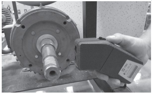
FIG. 2 Tachometer.
Example: Measured RPM is 1770 at partial load. Full-load nameplate RPM is 1740, and the nameplate horsepower is 10 hp. Partial-load slip is 30 RPM (1800 - 1770).
30 (1800 - 1740) = 0.5
The motor is operating at 0.5 × 10 hp, or 5 hp output.
MOTOR LOSSES
Motor losses within the motor affect motor efficiency. In the conversion of energy from electrical to mechanical, some losses are to be expected. Motor losses are grouped into several categories.
Core losses in the motor are made up of losses in the iron core. These losses are due to eddy currents in the motor iron, and hysteresis losses in the magnetic circuit of the motor iron. To reduce hysteresis losses, high-grade steel with a higher silicon content is used to reduce the friction of the magnetic materials and therefore reduce the heat produced in changing the magnetic fields of the motor iron. To reduce the eddy currents, the laminations are sliced thinner and electrically insulated from one another. In addition, by lengthening the core, there is less flux density in the core material and reduced losses due to magnetic effects.
Friction and windage losses are the results of the motor bearings and the friction encountered by the spinning rotor. If the friction of the bearings can be reduced, the motor will have less opposition to the turning shaft and reduced losses within the motor. Windage is the result of the needed cooling of the motor windings. If other losses, including core and copper losses, can be reduced, there is less need for cooling and the fan size and air movement can be reduced, which again reduce losses within the motor.
Copper losses include stator losses that occur in the copper winding of the stator. They are referred to as I^2 R losses. If the wire size in the stator winding can be increased, then the R (resistance) is reduced and the losses are reduced. The wire size is increased by larger slots in the stator and reduced thickness of the wire insulation. Copper losses occur in the rotor winding as well. By reducing the resistance of the rotor, the same benefits of reducing the wattage losses in the stator are realized, and motor efficiency is increased.
Stray losses make up the remaining motor losses. Stray losses occur because the magnetic flux created in the stator is lost and never reacts with the rotor conductors to produce torque.
By lengthening the core, stray losses are reduced. To accomplish all these reductions in losses, redesigns were needed. In most cases, more expensive materials and processes are used in high-efficiency motors. The original purchase price of a high-efficiency motor is higher than the price of a comparable horsepower, standard-efficiency motor. The operating cost for electricity for a high-efficiency or a premium-efficiency motor can be less than that for a standard motor if the motors are properly selected to take advantage of the actual load conditions of the motor.
MOTOR EFFICIENCY DESIGNATIONS
Premium efficiency motors are designed to run at 94.1% efficiency at full load. A high efficiency motor is designed to run at 91.0% efficiency. If a motor is more efficient, it means that a higher percentage of the input power measured in electrical watts is converted to output mechanical horsepower, compared to a lower efficiency motor. All electric motors have losses as described previously. The motor manufacturers have worked to reduce these internal losses even more producing a "premium efficiency" motor. If you were to run a "premium efficiency" 25 HP motor at full load for 24 hours per day and 7 days per week (8736 hours) at a total cost of $0.10 per kilowatt hour, you would pay:
• "Premium efficiency 94.1% eff " motor cost to operate: ( 25 hp _ 746 W
____
.941 _ 1000
) _ 8736 hours _
$0.10 per kilowatt hour _ (19.81 kW) _ 8736 × 0.10 _ $17,314
• A "high-efficiency 91% eff " motor would cost : ( 25 hp _ 746
__
.910 _ 1000
) _ 8736 _ .10 _ (20.5 kW) _ 8736 _ 0.10 _ (20.5 kW) _ 8736 _ 0.10 _ $ 17,904.
This represents a savings of approximately $590.00 per year.
A comparison formula:
Savings in dollars _ (0.746 kW per hp) _ (hp) _ ( 100
_ lower eff % _ 100
high eff % ) _ (RT) hours
of run time per year _ (E) energy cost in dollars per kWh, or approximately $586.00
Typically a premium efficiency motor runs at a cooler temperature, which extends motor life. The insulation temperature is a contributing factor to motor life. It is estimated that the insulation life doubles for every 10°C (50 °F) reduction in operating temperature. A cooler temperature also aids in bearing life. The cooler the motor runs usually means the longer the expected life.
Electric motors consume nearly 60% of the electric energy in the United States; therefore, the Energy Independence and Security Act (EISA) was created in 2007. The actual improvements in energy efficiencies were actually realized in 2010 by the motor manufacturers.
Motor manufacturers list their premium efficiency motors under different names.
Typically, the larger the motor hp, the higher the efficiency ratings. The highest efficiency ratings appear between 75% and 100% load. Power factor also typically improves with the hp rating of the motor and again tends to peak about 75% to 100% of full load.
Stator losses traditionally made up about 66% of the power losses in the I^2R losses of the stator windings. To increase efficiency, more copper was added to the stator windings to reduce the R and therefore reduce the I^2R losses. To reduce rotor losses, the slip was decreased to change the way the stator flux reacted with the rotor. This required increased conduction of the rotor bars. The following chart compares a standard efficiency motor to a premium efficiency motor and estimates the payback period for the higher priced premium motor. The comparisons are made at 75% of full load and use 7.5 cents per kWH for comparison purposes. The first chart compares replacing a functioning motor with a higher efficiency motor just to gain operating energy savings.
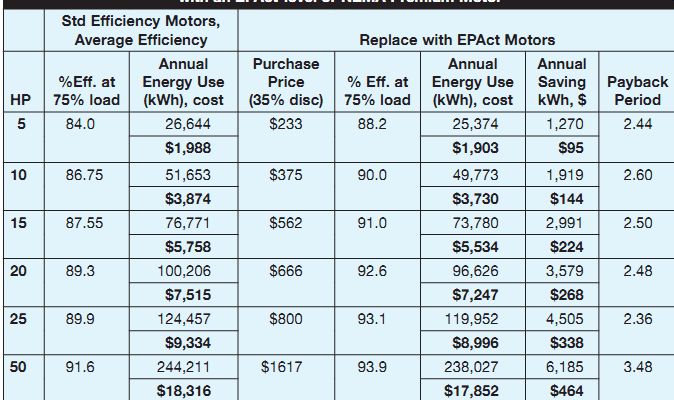
--------- Energy and Cost Savings Available When Replacing Serviceable
Standard Efficiency Motor with an EPAct-level or NEMA Premium Motor
The second chart compares replacing a failed motor with a premium efficiency motor and compares the payback time for the difference in motor cost and operating expenses.

------------ Comparison of Annual Savings and Simple Payback When Comparing
Replacement of a Failed Motor with an Epact-level or NEMA Premium Motor
MOTOR ENERGY REQUIREMENTS
When selecting motors to drive loads, an awareness of the loading effects on the energy drawn by the motor is important. The effects on the motor input energy can be estimated by how the motor is used and at what speed it is driven. The physical laws that determine the operating characteristics and application are known as the affinity laws or the cube load laws. In short, the laws of energy consumption state that the energy required to drive fans or pumps (motors used for moving volumes of air or water) is proportional to the cube of the speed. For example, if the speed of a fan is reduced to 50% of the rated full-load speed, the fan slows to 50% of the RPM. This in turn reduces the air volume delivered to 50% of the full volume. The change is a linear proportion. The air pressure also changes as the square of the speed changes. For 50% of normal speed, the pressure drops to 0.52, or 25% of normal full-speed pressure. However, the energy consumption changes to 50% cubed, or 0.53, yielding only 12.5 % of the energy used.
Several other examples, worked out using MotorMaster+ software, can be found elsewhere on this Web site.
Another example is that a reduction to 80% of the full-speed condition reduces the air volume to 80% and the pressure to 64% of the full pressure, but the energy used is reduced to 0.80 cubed, or 51.2% of the input electrical energy (see FIG. 3).
If the fan volume and pressure are sufficient to supply the needs of the facility, then operating below normal speed results in large savings for large fans and pumps. Variable frequency drives are ideal for tailoring the actual operating speed to facility needs. A typical application is an office that needs less volume and pressure for environmental air during off hours. A simple program to reduce speed may yield large energy and dollar savings.
Pumps work on the same physical laws when the speed of the pump, but not the speed of the impeller, is being changed. If the pressure and volume of a reduced-speed pump meets the demand of the mechanical system, then reduced speeds may be an effective energy reduction technique.
Many premium efficiency motors are also designed to be inverter duty rated. These motors are designed to run with variable frequency drives without affecting the life of the motor.
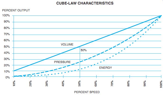
FIG. 3 Affinity laws, also known as cube load laws.
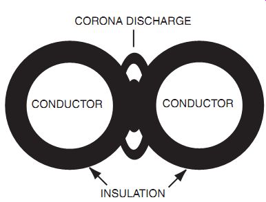
FIG. 5 Example of new cable design to help eliminate problems with wiring
supplying VFDs.
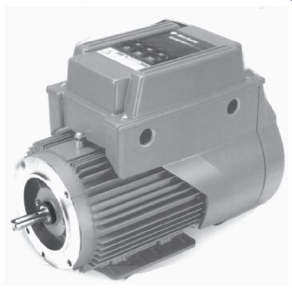
FIG. 6 Integrated electronic drive and motor combination.
When using energy reduction techniques, such as variable frequency drives, it may be wise to use motors designed for use with inverter drives. Inverter-duty and vector-drive motors are designed for this purpose. Because PWM and vector drives are switching the power at high speed, there is a tendency for a standard motor's magnet wire (motor winding) insulation to break down because of spikes that occur and punch through the standard wire insulation. Some motor manufacturers produce a line of motors specifically designed with magnet wire resistant to transient spikes (see FIG. 4). Often these motors need different cooling techniques that are standard for totally enclosed, fan-cooled (TEFC) motors. TEFC motors have external fins on the motor that radiate the heat to the motor surface. An external fan then blows ambient air over the fins to cool the motor. The fan is attached to the motor shaft and runs at the same speed as the motor shaft. If the motor uses a higher temperature-rated insulation on the windings, such as class H insulation, the motor can be totally enclosed, non-ventilated (TENV) or totally enclosed, blower cooled (TEBC).
Along with changes in motor design to accommodate different or lower than normal speeds, motor wiring also deserves attention. The wires that carry the power from the PWM drive to the motor must be able to handle the normal power levels of the PWM pulses, as well as the standing waves that produce high voltages on the wire and the insulation. It has been deter mined that there may be corona breakdown of the insulation caused by these high voltages.
Electrical noise has also been an observed problem for motors driven by variable frequency drives (VFDs). Cable manufacturers have developed products to counteract the effects of the problems associated with long lengths of leads from the VFD to the motor. FIG. 5 shows examples of special inverter-driven motor leads.
Another change in the motor and drive industry is the integration of the motor and the drive in a single unit (see FIG. 6). The drive has been specifically matched to the specific inverter-duty motor, which is a TEBC design. The internal leads from the drive to motor are designed for long life because of the reduction of corona and the reduction of reflected voltage wave. This integrated solution provides for perfectly matched components and easy, one-step, no-engineering installation.
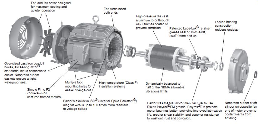
FIG. 4 Totally enclosed, blower-cooled (TEBC) inverter motor.
SUMMARY
Energy-efficient motors are designed to operate with less slip than conventional motors and to better use the input wattage to create output wattage or horsepower. In design and manufacturing, these motors are made with higher grade silicon steel and thinner laminations of the core steel to reduce core losses. The magnet wire used in the windings is larger gauge to reduce copper losses. If less heat is produced (lost) within the motor, the fan can be smaller, and less windage loss is incurred. If the bearings are of better quality than standard duty, then less friction is developed, and reduced losses occur there. In all, every effort is made to reduce the watt age lost inside the motor in the conversion of electrical to mechanical energy. To estimate the losses and efficiency, the output load must be determined. Several methods are used to estimate the load, and a few methods used to actually measure the output load.
When reducing the energy requirements of a fluid drive system-air or liquid-the results of the cube load energy law are effective. This law relates the effect on the fluid system to the amount of input energy needed to drive the load. To reduce the speed of a drive system to conserve energy, a VFD is used. Other factors, such as adequate cooling of the motor at lower speed, must be considered. Standard motors and supply leads used with PWM drives often fail due to voltage reactions. Motors are available with inverter-duty windings that are used to counteract the effects of the electronic drives. Leads are available to counteract the effects of the electronic drives on the motor supply leads. All these solutions can be purchased as a single matched unit in an integrated drive and motor set.
QUIZ
1. How many watts are equivalent to 10 hp?
2. Show the formula for determining the efficiency of a single-phase AC motor.
3. Calculate the horsepower output of a motor operating at 1750 RPM at 60 Hz. The full load nameplate RPM is 1725, and the rated horsepower is 7.5 hp.
4. Explain how the eddy current losses in a motor are reduced.
5. Name the two parts of the motor that create copper losses.
6. If the motor speed for a fan drive is reduced to 60% of the design speed, the motor power will be reduced to approximately of the rated power input.
a. 21.5%
b. 36%
c. 60%
d. 64%
7. What does TEBC stand for on a motor nameplate?