AMAZON multi-meters discounts AMAZON oscilloscope discounts
GOALS:
• list the main components of a wound-rotor, poly phase induction motor.
• describe how the synchronous speed is developed in this type of motor.
• describe how a speed controller connected to the brushes of the motor provides a variable speed range for the motor.
• state how the torque, speed regulation, and operating efficiency of the motor are affected by the speed controller.
• demonstrate how to reverse the direction of rotation of a wound-rotor induction motor.
Until the past several years, AC variable speed control was very difficult with a standard motor. Therefore, a different type of motor and control system was developed and used extensively for years. This motor is rarely installed as a new system now. Maintenance electricians must be familiar with this type of motor and control system.
Many industrial motor applications require three-phase motors with variable speed control. The squirrel-cage induction motor cannot be used without additional controls for variable speed work, because its speed is essentially constant. Another type of induction motor was developed for variable speed applications. This motor is called the wound-rotor induction motor or slip-ring AC motor.
WOUND-ROTOR AC MOTORS
Wound-rotor motor drives use a specially constructed AC motor to accomplish speed control and for their inherent ability to provide high starting torque with relatively low starting current.
These motors are now installed in heavy manufacturing needs such as ball mills, shredders, and cement mills, to provide a rugged motor with the ability to bring high-inertia loads up to speed smoothly. The windings of the motor rotor are brought out of the motor through slip rings on the rotor shaft. Fig. 1 shows an elementary diagram of a wound-rotor motor with an adjustable speed drive. These windings are connected to a controller that places variable resistors in series with the windings. The torque performance of the motor can be controlled using these variable resistors or liquid rheostats.
Wound-rotor motors are more common in the larger sizes, that is, 100 to 1000 hp and above.
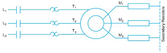
Fig. 1
Elementary diagram of an adjustable speed drive, wound-rotor motor.
Features of Wound-Rotor Motors
Wound-rotor motors have the following advantages, which make them suitable for a variety of applications:
• Cost--The initial cost is moderate for the high horsepower units.
• Control--Not all the power need be controlled, resulting in a moderate size and simple controller.
• Construction--The simple construction of the motor and control lends itself to maintenance without the need for a high level of training.
• High-inertia loads--The drive works well on high-inertia loads.
Disadvantages of Wound-Rotor Motors
Wound-rotor motors also have disadvantages:
• Custom motor--The motor has a rotor wound with wire and slip rings, and is not easily available, but is still manufactured.
• Efficiency--The drive does not maintain a high efficiency at low speeds.
• Speed range-The drive usually is limited to a speed range of two to one.
CONSTRUCTION DETAILS
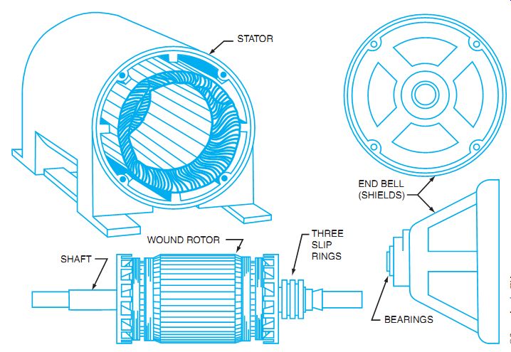
Fig. 2 Parts of a wound-rotor motor.
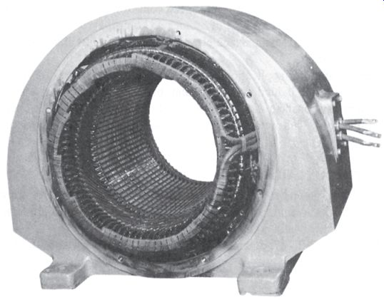
Fig. 3 Wound starter for a polyphase induction motor.
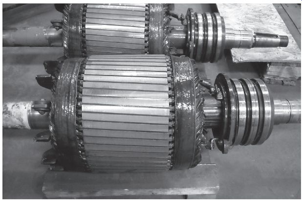
Fig. 4 Rotor of a wound rotor motor.
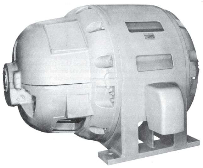
Fig. 5 Sleeve-bearing, wound-rotor, polyphase induction motor.
A wound-rotor induction motor consists of a stator core with a three-phase winding, a wound rotor with slip rings, brushes and brush holders, and two end shields to house the bearings that support the rotor shaft.
Figures 2, 3, 4, and 5 show the basic parts of a wound-rotor induction motor.
The Stator A typical stator contains a three-phase winding held in place in the slots of a laminated steel core, shown in Fig. 3. The winding consists of formed coils arranged and connected so that three single-phase windings are spaced 120 electrical degrees apart. The separate single phase windings are connected either in wye or delta. Three line leads are brought out to a terminal box mounted on the frame of the motor. This is the same construction as the squirrel-cage motor stator.
The Rotor
The rotor consists of a cylindrical core composed of steel laminations. Slots cut into the cylindrical core hold the formed coils of wire for the rotor winding.
The rotor winding consists of three single-phase windings spaced 120 electrical degrees apart. The single-phase windings are connected either in wye or delta. (The rotor winding must have the same number of poles as the stator winding.) The three leads from the three-phase rotor winding terminate at three slip rings mounted on the rotor shaft. Leads from carbon brushes that ride on these slip rings are connected to an external speed controller to vary the rotor resistance for speed control.
The brushes are held securely to the slip rings of the wound rotor by adjustable springs mounted in the brush holders. The brush holders are fixed in one position. For this type of motor, it is not necessary to shift the brush position as is sometimes required in DC generator and motor work.
The Motor Frame
The motor frame is made of cast steel. The stator core is pressed directly into the frame. Two end shields are bolted to the cast steel frame. One of the end shields is larger than the other because it must house the brush holders and brushes that ride on the slip rings of the wound rotor. In addition, it often contains removable inspection covers.
The bearing arrangement is the same as that used in squirrel-cage induction motors.
Either sleeve bearings or ball-bearing units are used in the end shields.
PRINCIPLE OF OPERATION
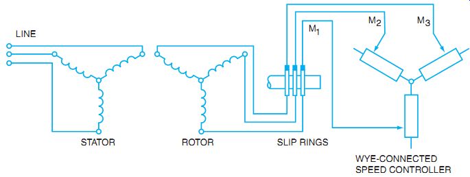
Fig. 6 Connections for a wound-rotor induction motor and a speed controller.
When three currents, 120 electrical degrees apart, pass through the three single-phase windings in the slots of the stator core, a rotating magnetic field is developed. This field travels around the stator. The speed of the rotating field depends on the number of stator poles and the frequency of the power source. This speed is called the synchronous speed and is determined by applying the formula used to find the synchronous speed of the rotating field of squirrel-cage induction motors.
Synchronous speed in RPM = 120 × Frequency in hertz
Number of poles or RPM = 120 × f p
As the rotating field travels at synchronous speed, it cuts the three-phase winding of the rotor and induces voltages in this winding. The rotor winding is connected to the three slip rings mounted on the rotor shaft. The brushes riding on the slip rings connect to an external wye connected group of resistors (speed controller), shown in Fig. 6. The induced voltages in the rotor windings set up currents that follow a closed path from the rotor winding to the wye connected speed controller. The rotor currents create a magnetic field in the rotor core based on transformer action. This rotor field reacts with the stator field to develop the torque that causes the rotor to turn. The speed controller is sometimes called the secondary resistance control.
Starting Theory of Wound-Rotor Induction Motors
To start the motor, all resistance of the wye-connected speed controller is inserted in the rotor circuit. The stator circuit is energized from the three-phase line. The voltage induced in the rotor develops currents in the rotor circuit. The rotor currents, however, are limited in value by the resistance of the speed controller. As a result, the stator current also is limited in value. In other words, to minimize the starting surge of current to a wound-rotor induction motor, insert the full resistance of the speed controller in the rotor circuit. The starting torque is affected by the resistance inserted in the rotor secondary. With resistance in the secondary, the power factor of the rotor is high or close to unity. This means that the rotor current is nearly in phase with the rotor-induced voltage. If the rotor current is in phase with the rotor-induced voltage, then the rotor magnetic poles are being produced at the same time as the stator poles. This creates a strong magnetic effect, which creates a strong starting torque. As the motor accelerates, steps of resistance in the wye-connected speed controller can be cut out of the rotor circuit until the motor accelerates to its rated speed.
Speed Control
The insertion of resistance in the rotor circuit not only limits the starting surge of current but also produces a high starting torque and provides a means of adjusting the speed. If the full resistance of the speed controller is inserted into the rotor circuit when the motor is running, the rotor current decreases and the motor slows down. As the rotor speed decreases, more voltage is induced in the rotor windings, and more rotor current is developed to create the necessary torque at the reduced speed.
If all resistance is removed from the rotor circuit, the current and motor speed increase. However, the rotor speed is always less than the synchronous speed of the field developed by the stator windings. Recall that this fact also is true of the squirrel-cage induction motor. The speed of a wound-rotor motor can be controlled manually or automatically with timing relays, contactors, and electronic speed control.
Through the use of solid-state controls, the wound-rotor motor can be started with the full secondary resistance in the circuit, and then the input power is also controlled to provide smooth acceleration and maximum torque. As the motor reaches full input voltage, the secondary resistors can be removed from the circuit, and the motor will operate with similar characteristics to a squirrel-cage motor. When resistance is reinserted in the secondary circuit, the motor speed slows, and the primary electronic drive can also be adjusted to provide gradual speed adjustment.
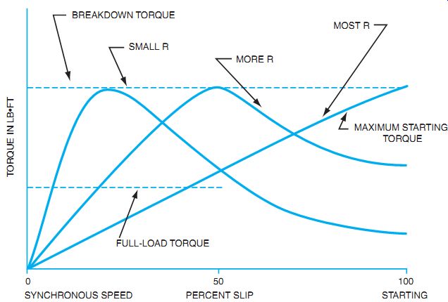
Fig. 7 Performance curves of a wound-rotor motor.
Torque Performance As a load is applied to the motor, both the percent slip of the rotor and the torque developed in the rotor increase. As shown in the graph in Fig. 7, the relationship between the torque and percent slip is practically a straight line.
Fig. 7 illustrates that the torque performance of a wound-rotor induction motor is good whenever the full resistance of the speed controller is inserted in the rotor circuit.
The large amount of resistance in the rotor circuit causes the rotor current to be almost in phase with the induced voltage of the rotor. As a result, the field set up by the rotor current is almost in phase with the stator field. If the two fields reach a maximum value at the same instant, there will be a strong magnetic reaction resulting in a high torque output. However, if all speed controller resistance is removed from the rotor circuit and the motor is started, the torque performance is poor. The rotor circuit minus the speed controller resistance consists largely of inductive reactance. This means that the rotor current lags behind the induced voltage of the rotor, and thus the rotor current lags behind the stator current. As a result, the rotor field set up by the rotor current lags behind the stator field that is set up by the stator current. The resulting magnetic reaction of the two fields is relatively small, because they reach their maximum values at different points. In summary, then, the starting torque output of a wound-rotor induction motor is poor when all resistance is removed from the rotor circuit.
Speed Regulation
As discussed previously, inserting resistance at the speed controller improves the starting torque of a wound-rotor motor at low speeds. However, there is an opposite effect at normal speeds. In other words, the speed regulation of the motor is poorer when resistance is added in the rotor circuit at a higher speed. For this reason, the resistance of the speed controller is removed as the motor comes up to its rated speed.
Fig. 8 shows the speed performance of a wound-rotor induction motor. Note that the speed characteristic curve resulting when all the resistance is cut out of the speed controller indicates relatively good speed regulation. The second speed characteristic curve, resulting when all the resistance is inserted in the speed controller, has a marked drop in speed as the load increases. This indicates poor speed regulation.
Power Factor
The power factor of a wound-rotor induction motor at no load is as low as 15% to 20% lag. However, as load is applied to the motor, the power factor improves and increases to 85% to 90% lag at rated load.
Fig. 9 shows a graph of the power factor performance of a wound-rotor induction motor from a no-load condition to full load. The low lagging power factor at no load is because the magnetizing component of load current is such a large part of the total motor current. The magnetizing component of load current magnetizes the iron, causing interaction between the rotor and the stator by mutual inductance.
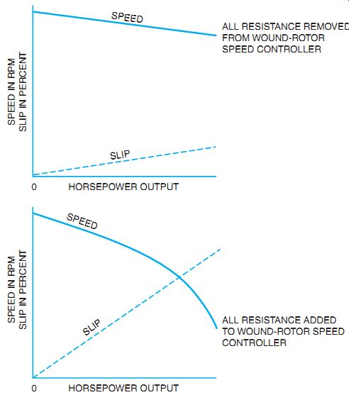
Fig. 8 Speed performance curves of a wound-rotor motor.
As the mechanical load on the motor increases, the in-phase component of current increases to supply the increased power demands. The magnetizing component of the current remains the same, however. Because the total motor current is now more nearly in phase with the line voltage, there is an improvement in the power factor.
Operating Efficiency
Both a wound-rotor induction motor with all the resistance cut out of the speed controller and a squirrel-cage induction motor show nearly the same efficiency performance. However, when a motor must operate at slow speeds with all the resistance cut in the rotor circuit, the efficiency of the motor is poor because of the power loss in watts in the resistors of the speed controller.
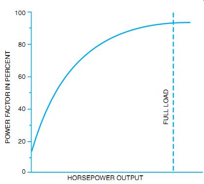
Fig. 9 Power factor of a wound-rotor induction motor.
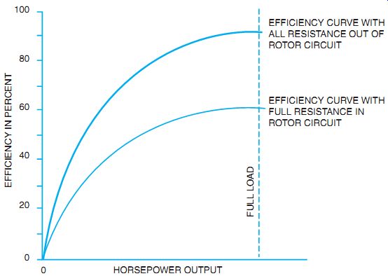
Fig. 10 Efficiency curves for a wound-rotor induction motor. EFFICIENCY
CURVE WITH ALL RESISTANCE OUT OF ROTOR CIRCUIT EFFICIENCY CURVE WITH FULL RESISTANCE
IN ROTOR CIRCUIT
Fig. 10 illustrates the efficiency performance of a wound-rotor induction motor.
The upper curve shows the highest operating efficiency results when the speed controller is in the fast position and no resistance is inserted in the rotor circuit.
The lower curve shows a lower operating efficiency. This occurs when the speed controller is in the slow position and all controller resistance is inserted in the rotor circuit.
Reversing Rotation
The direction of rotation of a wound-rotor induction motor is reversed by interchanging the connections of any two of the three line leads, shown in Fig. 11. This procedure is identical to the procedure used to reverse the direction of rotation of a squirrel-cage induction motor.
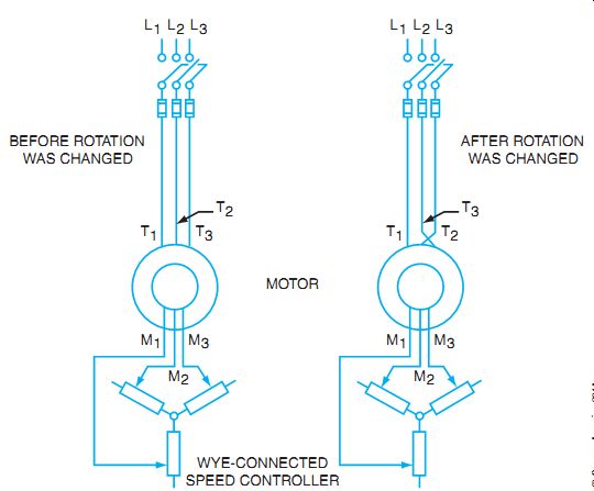
Fig. 11 Changes necessary to reverse direction of rotation of a wound-rotor
motor.
The electrician should never attempt to reverse the direction of rotation of a wound-rotor induction motor by interchanging any of the leads feeding from the slip rings to the speed controller. Changes in these connections will not reverse the direction of rotation of the motor.
SUMMARY
The wound-rotor motor is rarely installed as a new motor today, but many of these motors are still in use. Wound-rotor motors are typically larger horsepower motors assigned to special applications. The wound-rotor motor may be used for variable speed with the insertion of secondary resistors. The starting current and starting torque of the motor were the prime considerations when selecting the wound-rotor motor for installation. There are still many references to the wound-rotor motor used in the National Electrical Code.
QUIZ
A. Provide complete answers to questions 1 through 9.
1. List the essential parts of a wound-rotor induction motor. __
2. List two reasons why a wound-rotor induction motor is started with all resistance inserted in the controller. _____
3. A wound-rotor induction motor has six poles and is rated at 60 hertz. The full-load speed of this motor with all the resistance cut out of the speed controller is 1120 RPM. What is the synchronous speed of the field set up by the stator windings? ____
4. Determine the percent slip at the rated load for the motor in question 3.
5. Why is a wound-rotor induction motor used in place of a squirrel-cage induction motor for some industrial applications?
6. Why is the percent efficiency of a wound-rotor induction motor poor when operating at rated load with all resistance inserted in the speed controller?
7. What must be done to reverse the direction of rotation of a wound-rotor induction motor?
8. Why is the power factor of a wound-rotor induction motor poor at no load?
9. List the two factors that affect the synchronous speed of the rotating magnetic field set up by the current in the stator windings.
B. Select the correct answer for the statements in items 10 through 17, and place the corresponding letter in the space provided.
10. The speed of a wound-rotor motor is increased by a. inserting resistance in the primary circuit.
b. inserting resistance in the secondary circuit.
c. decreasing the resistance in the secondary circuit.
d. decreasing the resistance in the primary circuit.
11. The starting current of a wound-rotor induction motor is limited by _
a. decreasing the resistance in the primary circuit.
b. decreasing resistance in the secondary circuit.
c. inserting resistance in the primary circuit.
d. inserting resistance in the secondary circuit.
12. The direction of rotation of a wound-rotor motor is changed by interchanging any two of the three:
a. L1, L2, or L3.
b. T1, T2, or T3.
c. M1, M2, or M3.
d. all of the above
13. Wound-rotor motors can be used with ___
a. manual speed controllers.
b. automatic speed controllers.
c. pushbutton selection.
d. all of the above
14. The full-load efficiency of a wound-rotor motor is best when _
a. all resistance is cut out of the secondary circuit.
b. all resistance is cut in the secondary circuit.
c. it is running slowly.
d. it is running at medium speed.
15. The main advantage of the wound-rotor polyphase motor is that it __
a. has a low starting torque.
b. has a wide speed range.
c. will reverse rapidly.
d. has a low speed range.
16. The wound-rotor motor is so named because
a. the rotor is wound with wire.
b. the stator is wound with wire.
c. the controller is wound with wire.
d. all of the above are true
17. The magnetizing component of load current
a. is a small part of the total motor current at no load.
b. magnetizes the iron, causing interaction between the rotor and the stator.
c. is a large part of the total motor current at full load.
d. is unrelated to the power factor.