AMAZON multi-meters discounts AMAZON oscilloscope discounts
GOALS:
• list the basic parts in the construction of a synchronous motor.
• define and describe an amortisseur winding.
• describe the basic operation of a synchronous motor.
• describe how the power factor of a synchronous motor is affected by an under excited DC field, a normally excited DC field, and an overexcited DC field.
• list at least three industrial applications of the synchronous motor.
The synchronous motor, shown in Fig. 1, is a three-phase AC motor that operates at a constant speed from a no-load condition to full load. This type of motor has a revolving field that is separately excited from a DC source. In this respect, it is similar to a three-phase AC generator. If the DC field excitation is changed, the power factor of a synchronous motor can be varied over a wide range of lagging and leading values.
The synchronous motor is used in many industrial applications because of its fixed speed characteristic over the range from no load to full load. This type of motor is also used to correct or improve the power factor of three-phase AC industrial circuits, thereby reducing operating costs.
CONSTRUCTION DETAILS
A three-phase synchronous motor basically consists of a stator core with a three-phase winding (similar to an induction motor), a revolving DC field with an auxiliary or amortisseur winding and slip rings, brushes and brush holders, and two end shields housing the bearings that sup port the rotor shaft. An amortisseur winding (Fig. 2) consists of copper bars embedded in the cores of the poles. The copper bars of this special type of squirrel-cage winding are welded to end rings on each side of the rotor.
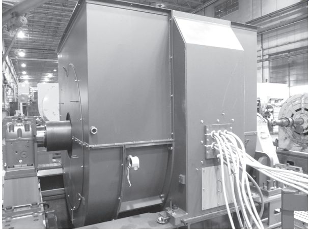
Fig. 1 Synchronous motor under construction.
Both the stator winding and the core of a synchronous motor are similar to those of the three phase AC induction motor and the wound-rotor induction motor. The leads for the stator winding are marked T1, T2, and T3 and terminate in an outlet box mounted on the side of the motor frame.
The rotor of the synchronous motor has salient field poles. The field coils are connected in series for alternate polarity. The number of rotor field poles must equal the number of stator field poles. The field circuit leads are brought out to two slip rings mounted on the rotor shaft for brush-type motors. Carbon brushes mounted in brush holders make contact with the two slip rings. The terminals of the field circuit are brought out from the brush holders to a second terminal box mounted on the frame of the motor. The leads for the field circuit are marked F1 and F2. A squirrel-cage, or amortisseur, winding is provided for starting because the synchro nous motor is not self-starting without this feature. The rotor shown in Fig. 2 has salient poles and an amortisseur winding.
Two end shields are provided on a synchronous motor. One of the end shields is larger than the second shield because it houses the DC brush-holder assembly and slip rings. Either sleeve bearings or ball-bearing units are used to support the rotor shaft. The bearings are also housed in the end shields of the motor.
PRINCIPLE OF OPERATION
When the rated three-phase voltage is applied to the stator windings, a rotating magnetic field is developed. This field travels at the synchronous speed. As stated in previous sections, the synchronous speed of the magnetic field depends on the frequency of the three-phase voltage and the number of stator poles.
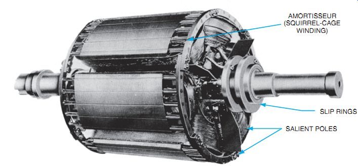
Fig. 2 A synchronous motor with amortisseur winding.
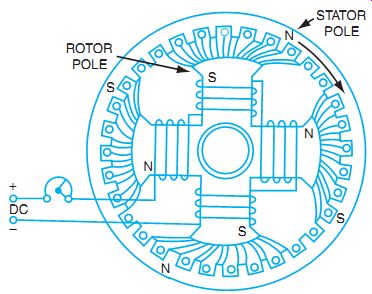
Fig. 3 Diagram showing the principle of operation of a synchronous motor.
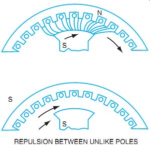
Fig. 4 Starting of synchronous motors.
The magnetic field that is developed by the stator windings travels at synchronous speed and cuts across the squirrel-cage winding of the rotor. Both voltage and current are induced in the bars of the rotor winding. The resulting magnetic field of the amortisseur (squirrel-cage) winding reacts with the stator field to create a torque that causes the rotor to turn.
The rotation of the rotor increases in speed to a point slightly below the synchronous speed of the stator, about 92% to 97% of the motor rated speed. There is a small slip in the speed of the rotor behind the speed of the magnetic field set up by the stator. In other words, the motor is started as a squirrel-cage induction motor.
The field circuit is now connected to a source of direct current, and fixed magnetic poles are set up in the rotor field cores. The magnetic poles of the rotor are attracted to the unlike magnetic poles set up by the stator magnetic field.
Fig. 3 and Fig. 4 show how the rotor field poles lock with unlike poles of the stator field. After the field poles are locked, the rotor speed becomes the same as the speed of the magnetic field set up by the stator windings. In other words, the speed of the rotor is now equal to the synchronous speed.
Remember that a synchronous motor must always be started as a three phase AC induction motor with the DC field excitation disconnected. The DC field circuit is added only after the rotor accelerates to a value near the synchro nous speed. The motor then operates as a synchronous motor, locked in step with the stator rotating field.
If an attempt is made to start a three-phase synchronous motor by first energizing the DC field circuit and then applying the three-phase voltage to the stator windings, the motor will not start because the net torque is zero.
At the instant the three-phase voltage is applied to the stator windings, the magnetic field set up by the stator current turns at the synchronous speed. The rotor, with its magnetic poles of fixed polarity, is attracted first by an unlike stator pole and attempts to turn in that direction. However, before the rotor can turn, another stator pole of opposite polarity moves into position, and the rotor then attempts to turn in the opposite direction. Because of this action of the alternating poles, the net torque is zero and the motor does not start.
DC Field Excitation
In early models, the field circuit is excited from an external DC source. A DC generator may be coupled to the motor shaft to supply the DC excitation current.
Fig. 5 shows the connections for a synchronous motor. A field rheostat in the separately excited field circuit varies the current in the field circuit. Changes in the field current affect the strength of the magnetic field developed by the revolving rotor. Small variations in the rotor field strength do not immediately affect the motor, which continues to operate at a constant speed. However, changes in the DC field excitation do change the power factor of a synchronous motor.
Brushless Solid-State Excitation
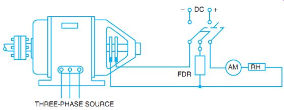
Fig. 5 External connections for a synchronous motor.
An improvement in synchronous motor excitation is the development of the brushless DC exciter. The commutator of a conventional direct-connected exciter is replaced with a three-phase, bridge-type, solid-state rectifier. The DC output is then fed directly to the motor field winding. Simplified circuitry is shown in Fig. 6. A stationary field ring for the AC exciter receives DC from a small rectifier in the motor control cabinet. This rectifier is powered from the AC source. The exciter DC field is also adjustable. Rectifier solid-state diodes change the exciter AC output to DC. This DC is the source of excitation for the rotor field poles.
Silicon-controlled rectifiers, activated by the solid-state field control circuit, replace electromechanical relays and the contactors of the conventional brush-type synchronous motor.
The field discharge resistor is inserted during motor starting. At motor synchronizing pull-in speed, the field discharge circuit is automatically opened and DC excitation is applied to the rotor field pole windings. Excitation is automatically removed if the motor pulls out of step (synchronization) due to an overload or a voltage failure. The brushless rotor is shown in Fig. 7. Mounted on the rotor shaft is the armature of the AC exciter, the AC output of which is rectified to DC by the silicon diodes. Brush and commutator problems are eliminated with this system. (The stator of a brushless motor is similar to that of a brush type of motor.)
Power Factor
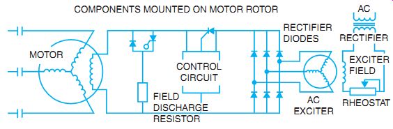
Fig. 6 Simplified circuit for a brushless synchronous motor.
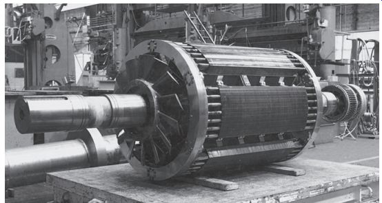
Fig. 7 Rotor of a brushless synchronous motor.
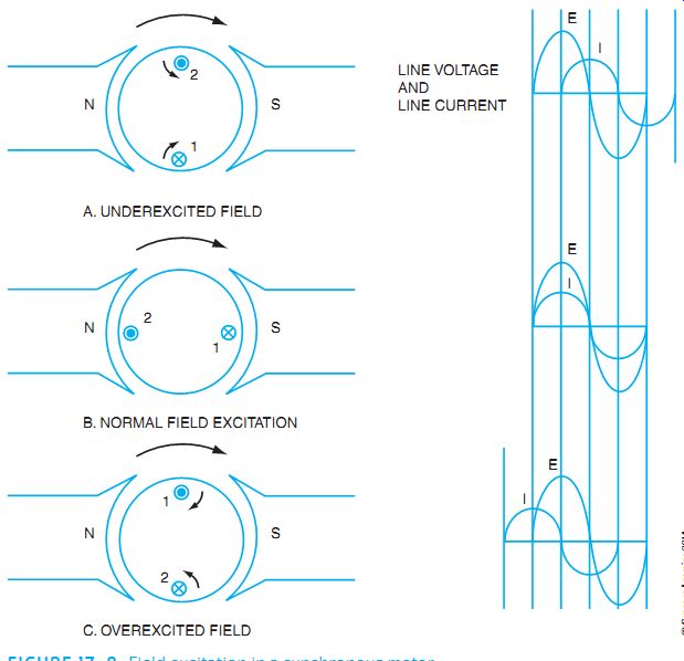
Fig. 8 Field excitation in a synchronous motor.
A poor lagging power factor results when the field current is decreased below normal by inserting all the resistance of the rheostat in the field circuit. The three-phase AC circuit to the stator supplies some magnetizing current, which helps strengthen the weak DC field. This magnetizing component of current lags the voltage by 90 electrical degrees. Because the magnetizing component of current becomes a large part of the total current input, a low lagging power factor results.
If a weak DC field is strengthened, the power factor improves. As a result, the three-phase AC circuit to the stator supplies less magnetizing current. The magnetizing component of current becomes a smaller part of the total current input to the stator winding, and the power factor increases. If the field strength is increased sufficiently, the power factor increases to unity, or 100%. When a power factor value of unity is reached, the three-phase AC circuit does not supply any rotor current and the DC field circuit supplies all current necessary to maintain a strong rotor field. The value of DC field excitation required to achieve unity power factor is called normal field excitation.
If the magnetic field of the rotor is strengthened further by increasing the DC field current above the normal field excitation value, the power factor decreases. However, the power factor is leading when the DC field is overexcited. The three-phase AC circuit feeding the stator winding delivers a demagnetizing component of current that opposes the too-strong rotor field. This action results in a weakening of the rotor field to its normal magnetic strength.
The diagrams in Fig. 8 show how the DC field is aided or opposed by the magnetic field set up by the AC windings. It is assumed in Fig. 8 that the DC field is stationary and a revolving armature is connected to the AC source. Keep in mind the fact that most synchro nous motors have stationary AC windings and a revolving DC field. For either case, however, the principle of operation is the same.
Fig. 9 shows two characteristic operating curves for a three-phase synchronous motor. With normal full-field excitation, the power factor has a peak value of unity, or 100% and the AC stator current is at its lowest value. As the DC field current is decreased in value, the power factor decreases into the lag quadrant, and there is a resulting rapid rise in the AC stator current. If the DC field current is increased above the normal field excitation value, the power factor decreases in the lead quadrant, and a rapid rise in the AC stator current results.
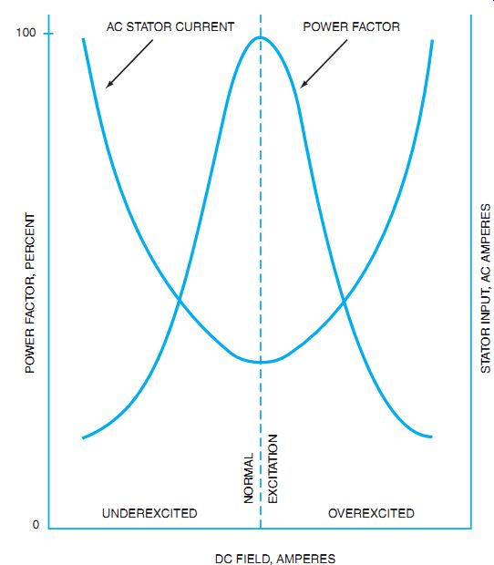
Fig. 9 Characteristic operating curves for synchronous motors.
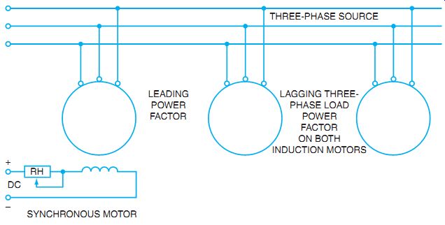
Fig. 10 Synchronous motor used to correct power factor.
It has been shown that a synchronous motor operated with an overexcited DC field has a leading power factor. For this reason, a three-phase synchronous motor is often connected to a three-phase industrial feeder circuit with a low lagging power factor. In other words, the synchronous motor with an overexcited DC field helps correct the power factor of the industrial feeder circuit.
In Fig. 10, two induction motors with lagging power factors are connected to an industrial feeder circuit. The synchronous motor connected to the same feeder is operated with an overexcited DC field. Because the synchronous motor can be adjusted so that the resulting power factor is leading, the power factor of the industrial feeder can be corrected until it reaches a value near unity, or 100%.
Reversing Rotation
The direction of rotation of a synchronous motor is reversed by interchanging any two of the three line leads feeding the stator winding. The direction of rotation of the motor does not change if the two conductors of the DC source are interchanged.
INDUSTRIAL APPLICATIONS
The three-phase synchronous motor is used when a prime mover having a constant speed from a no-load condition to full load is required, such as fans, air compressors, and pumps.
The synchronous motor is used in some industrial applications to drive a mechanical load and also to correct the power factor. In some applications, this type of motor is used only to correct the power factor of an industrial power system. When the synchronous motor is used only to correct the power factor and does not drive any mechanical load, it serves the same purpose as a bank of capacitors used for power factor correction. Therefore, in such an installation the motor is called a synchronous capacitor.
Three-phase synchronous motors up to a rating of 10 hp are usually started directly across the rated three-phase voltage. Synchronous motors of larger sizes are started through a starting compensator or an automatic starter. In this type of starting, the voltage applied to the motor terminals at the instant of start is about half the value of the rated line voltage, and the starting surge of current is limited.
SUMMARY
The AC synchronous motor is used where speed must be kept constant. As the name implies, the motor runs at the designed synchronous speed. The principle used in the larger three-phase synchronous motors is to provide a DC field for the rotor. The methods may vary in the application of the DC. Some motors use an external DC source and feed the DC to the rotor via slip rings. Other motors control a magnetic field to the rotor and use solid-state rectifiers to create DC in the rotor. In either case, the rotor field can change the power factor of the synchronous motor and allow it to act as a source of leading-power factor, thereby correcting the normal lagging power factor of an industrial power system.
QUIZ
A. Fill in the answers to questions 1 through 9.
1. List the basic parts of a three-phase synchronous motor.
2. What is an amortisseur winding?
3. Explain the proper procedure to use in starting a synchronous motor.
4. A three-phase synchronous motor with six stator poles and six rotor poles is operated from a three-phase, 60 Hz line of the correct voltage rating. Determine the speed of the motor.
5. How is a leading power factor obtained with a three-phase synchronous motor?
6. What is the purpose of a rheostat in the separately excited DC field circuit of a synchro nous motor?
7. How is the direction of rotation of a three-phase synchronous motor reversed?
8. State two important applications for three-phase synchronous motors.
9. What is a synchronous capacitor?
B. Select the correct answer for the statements in items 10 through 14, and place the corresponding letter in the space provided.
10. A synchronous motor must be started __.
a. with full DC in the field circuit.
b. with weak DC in the field circuit.
c. as an induction motor.
d. when the power factor is low.
11. The speed of a synchronous motor ____.
a. is constant from no load to full load.
b. drops from no load to full load.
c. increases from no load to full load.
d. is variable from no load to full load.
12. A synchronous motor with an underexcited DC field has __.
a. a leading power factor.
b. a lagging power factor.
c. less synchronous speed.
d. no effect.
13. The power factor of a synchronous motor can be varied by changing the _____.
a. brush polarity.
b. phase rotation.
c. speed of rotation.
d. field excitation.
14. A synchronous motor running on the three-phase line voltage serves the same function of power factor correction as _
a. a bank of resistors.
b. a bank of capacitors.
c. an induction motor.
d. a wound-rotor motor.