AMAZON multi-meters discounts AMAZON oscilloscope discounts
GOALS:
• use the correct terminology when selecting the proper motor-controller parameters.
• identify the operating characteristics of solid-state starters.
• determine the advantages and disadvantages of solid-state starters.
• determine the correct application of solid-state pilot devices.
• note the differences between National Electrical Manufacturers Association (NEMA) controllers and International Electrotechnical Commission (IEC) controllers.
In addition to the variable frequency speed controls covered in section 15, many motors are being installed with electronic controllers. The starters are more reliable than ever and have many features that are not available on conventional electromechanical starters. These starters can be used for a variety of applications, including pumps, blowers, compressors, chillers, and any other motor use. They can be used on induction, synchronous, multispeed, reversing, and even wound-rotor motors. DC motor drives are described in section 6.
DIGITAL CONTROLLERS
Many of the electronic solid-state starters now available have advanced features that allow the electrician to choose just the right parameters to fit the intended control need. With the spread of worldwide control companies, most starters are designed to operate over a range of supply voltages and frequencies. Many starters are programmable so that the field electrician can make adjustments to specially start, stop, and monitor the motor operations. This starter can be programmed using a remote digital display to set the controller for the desired motor full-load amperes (FLA). It allows the user to set the controller to the proper motor service factor as well as motor acceleration and deceleration. It also may protect the motor from phase imbalance or improper phase sequence. The electronic controller can monitor current to the motor and protect the motor from overload, selected as class 10, 20, or 30 overload. It may open the line power if one phase is lost on a three-phase line (a condition known as single phasing).
Features available on many digital solid-state starters include over- or under-voltage protection, or voltage-unbalance protection. Ground-fault protection may also be chosen as an option with many of the controllers. Many of the manufacturers also offer display readout of fault conditions with the sequence of faults and conditions. This helps in the troubleshooting procedures when trying to ascertain conditions that occurred when the motor stopped functioning normally.
The programmable parameters must be set when installing a new electronic drive. A common parameter is the motor FLA, which is set based on the motor nameplate rating. This setting is designed to program the controller for a specific motor and adjust the operating characteristics to meet that particular motor's operation. A motor overload parameter is set based on the motor service factor. If the motor is able to run with a percentage overload of the design horsepower, the controller needs the information to detect when a dangerous motor overload occurs. Service factors may range from 1.0 to 1.4. Service factor (SF) 1 (or 100%) means no overload is tolerated by the motor design. SF 1.4 means that the motor can withstand 140% overload without damage to the motor windings. The overload current sensors must have the appropriate information to track motor operations.
Starting current parameters are established to determine how much current is to be delivered to the motor during start-up. It should be set to allow the motor to start turning as soon as the start command is given. In some starters, this parameter is listed as a percent age of the FLA of the motor. If the motor does not begin turning when the start command is received, then increase the value in small increments. If the motor accelerates too quickly and the starting torque is too hard on the driven load, then try reducing the starting current parameter. The maximum starting current parameter must be set. This setting is designed to limit the current to a maximum value based on the electrical supply requirements.
The motor may not require the maximum value, but the limit will keep too much current from being drawn from the electric supply. This control should be checked with the next control to make sure the motor achieves full speed during the time limit set by the ramp-up time parameter.
Motor ramp-up time is the setting that determines how much time is to elapse before the motor is at full speed with full voltage and current applied. It controls the time in seconds between initial motor current setting and the time when maximum motor current is applied to the starting motor. Associated with the ramp-up time is the motor stall-time parameter. The stall time determines the seconds allowed from the end of the ramp-up time until the motor reaches full operating speed before the controller disconnects the motor from the line.
Other parameters to select are the deceleration modes. Some controllers have multiple modes for deceleration. There may be an initial level of voltage applied to the motor when the stop command is issued. This allows the voltage to the motor to slowly decrease and provide gradual stopping. If you need the motor to come to a quick stop, set this selection to 0 or no ramp-down voltage. As in the increasing speed mode, or acceleration mode, the next parameter is programmed with consideration of the deceleration time setting made in the next step. The deceleration voltage level 2 is set to control the voltage after the ramp-down time has expired, but the motor is still not at rest. This step 2 sets the end of the ramp voltage that the motor will receive as it is decelerating. If the motor is still turning at the end of the ramp down time, decrease the step 2 voltage setting. The time setting for the deceleration is the next parameter. Set this to the desired time that is required for the motor to decelerate. This is not a braking control.
Line current imbalance is another commonly set point. If the phase currents to the motor are different by anywhere from 5% to 40% and the difference occurs for more than 10 seconds, the motor will be disconnected from the line to prevent it from being damaged by the single-phasing condition.
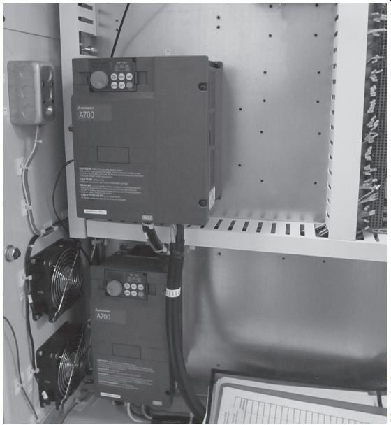
FIG. 1 Solid-state motor controllers mounted in cabinets.
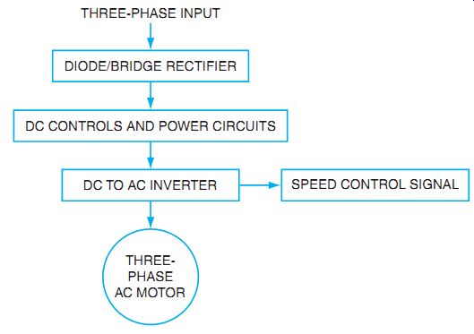
FIG. 2 Block diagram of a typical AC variable-frequency electronic drive.
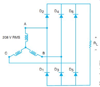
FIG. 3 A wye source supplies power to a three phase, full-wave rectifier.
BASIC OPERATIONS
Electronic controllers are packaged in a ready-to-use style (see FIG. 1). They are sized in various categories to accommodate standard motor sizing. Some electronic controllers use the pulse-width-modulation (PWM) method of controlling output voltage and motor current; some use a variation of the PWM drive; and some of the newest controllers use a flux vector method of controlling the output to the motor. The difference between the two systems is in the feedback of motor operations to the controller and the sophistication of the microprocessor controller.
The PWM electronic drives with variable voltage control use a sequence of control that is simplified in FIG. 2. In this block diagram, the incoming power is rectified and filtered in the initial stage of the controller with a three-phase rectifier circuit, as shown in FIG. 3. A microprocessor controls the firing of the output controller, based on the parameters selected and the information from the controller sensors. The output is con trolled by a configuration of transistors of a type called insulated gate bipolar transistor (IGBT). These electronic devices control the frequency and the amount of voltage that is delivered to the motor. By turning on the DC voltage for varying lengths of time, the pulses of DC are controlled and create an approximation of a sinewave output (see FIG. 4). By adjusting the pulse width, or the time of pulses, and the modulation of the voltage available, PWM controls the frequency and the level of the output voltage supplied to the motor. A microprocessor responds to the input parameter selection and drives the motor to the design limits set by the operator.
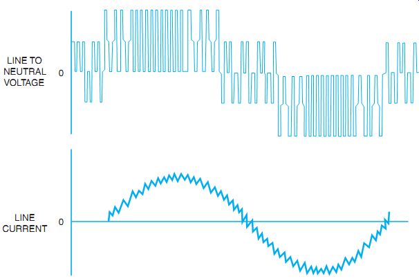
FIG. 4 PWM output waveforms. Each phase has the same waveform.
Adjusting the frequency to an AC motor directly affects its speed. If the frequency applied is lower than the nameplate design frequency, the inductive reactance of the motor is lower, and the input voltage must be lowered to compensate for this reduced reactance of the winding.
Line and output reactors may be included to reduce the disturbances to the power line. Because this is a high-speed switching device, it is considered a nonlinear load to the power source, and electrical harmonics are generated. The reactors help reduce the effects of the harmonics on the supply system. Note that there are several input points for digital inputs, such as contact closures, and the analog input points are typically for a speed-setting potentiometer. The out put points are used to relay information to the user in the form of contact closure for indicating lights or other needed alarms. The analog output can be used to drive other devices or as a monitor point for process control.
The flux-vector drive is an advancement in the PWM control for motors. If the motor is to run at set frequencies for extended periods and there are not a lot of load fluctuations, the speed stays nearly constant. If, however, there is a need for precise speed control and the load fluctuates considerably, then the flux-vector drive is needed. The advantage of the flux vector is derived from the feedback information to the controller from the output to the motor. It can produce maximum torque at all speeds, and the response to changing load is nearly instantaneous for speed changes. The term vector is used to describe the operating characteristics that react like a vector in mathematics. The vector describes direction and magnitude. The flux (magnetic fields) of the motor can be controlled like a vector to change magnitude and relative position of the magnetic fields in the motor. If the rotor flux and the stator flux can maintain an optimum 90° relationship to each other, then maximum torque is produced. This is the goal of adjusting the magnetic flux of the stator to create a 90° separation from the rotor flux.
A squirrel-cage motor produces rotor flux because it slips behind the stator magnetic field. The slip is measured in percent slip. Normally, the slip is 3% to 5% for a normal motor at full load. The slip can also be measured as an angular velocity in hertz. As the motor is loaded, the slip increases and the angular velocity increases, or the hertz slip increases. By monitoring the relative amount of flux in the stator (the magnitude) and the relative position of the flux (the direction of the vector), the controller uses a series of calculations to determine the exact speed and torque of the motor. The input and output sections are similar to the PWM drive.
The controller is the difference. By sensing the magnitude of the current to the motor, a cur rent feedback is created. By sensing speed in relation to the current, a speed feedback is created.
The speed is monitored by a tachometer, an encoder, or a resolver. This signal is returned to the microprocessor controller, and then the PWM output is controlled to respond. The output is thus monitored to maintain set speed at a desired torque, and the field intensity and orientation are controlled for accurate speed control (see FIG. 5).
Another form of the vector drive is called the sensorless vector drive. In this method, the manufacturer does not provide a direct connection to the motor through a speed sensor, but instead measures the different components of the current delivery to the motor. The concept of the flux-vector control is the same as in the sensor type of control, that is, to monitor the cur rent that produces flux and the current that produces torque and calculate the angle between them. This combination of the two force vectors, magnetic flux vector and torque vector, creates the desired optimum combination of the two forces. Current sensors designed to measure the different vector currents are part of the control system. FIG. 6 shows the basic control scheme. With the measurements, the microprocessor is used to calculate the slip and therefore can compensate for speed and torque changes by adjusting the output IGBTs.
CORRECT APPLICATION
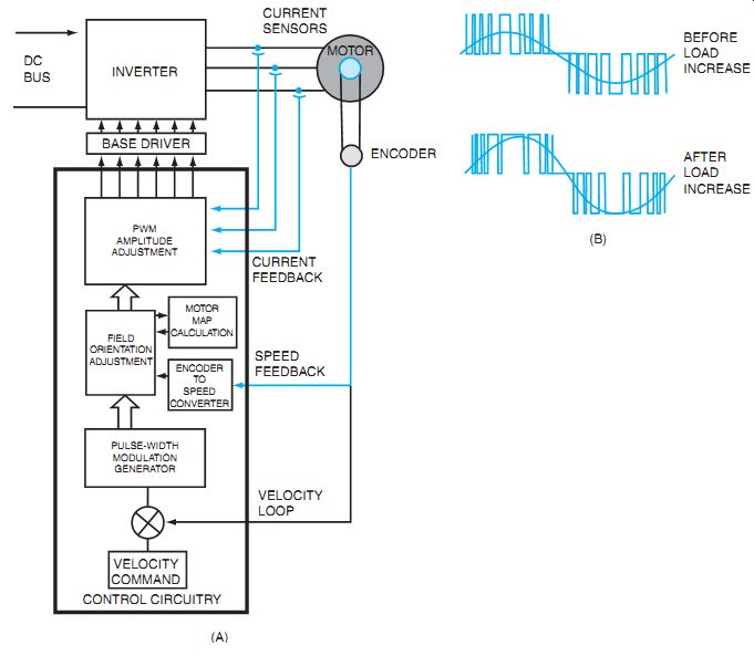
FIG. 5 Block diagram of vector-drive control.
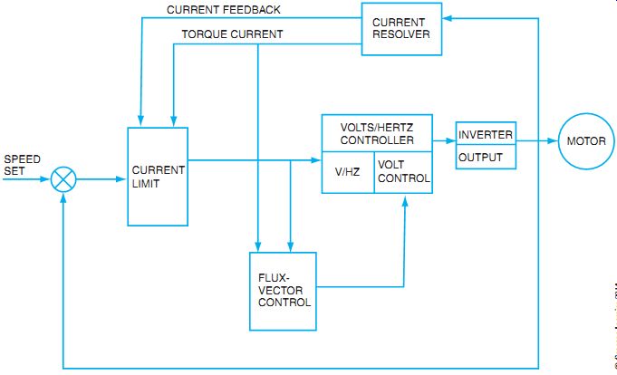
FIG. 6 Basic block diagram of flux-vector controller.
When selecting a starter for a particular motor drive situation, you should consider several things. Is there a need for solid-state starting if the driven machinery of the electrical supply lines requires a form of reduced-voltage/reduced-current starting? Consider whether the driven machinery can start with reduced torque, compared to full voltage ATL starting. In some cases, the motor can be brought up to speed with an electronic drive, and then if it is to run at a constant speed, the electronics can be bypassed with an electromechanical starter. The advantages to this method are that the electronics are not used on a continuous basis, and the heat generated by the electronic switching does not have to be dissipated by the heat sinks. The efficiency of the drive increases because little power is lost in the electronic rectification and inverters back to the AC for the motor.
If the motor is to have multiple set speeds, the correct number of frequency set points must be determined and matched with the controller's capability. This is a feature that allows the user to set specific frequencies that the controller will hold for extended periods. If these are standard motor speeds, a consideration would be to use a simple control and a multispeed motor. Depending on the need for accuracy of the motor speed and the amount of control desired, various methods of control may be considered. A simple PWM drive is fairly accurate but does not use much feedback from the motor, whereas a vector drive has tighter control and more feedback from the motor operations.
SOLID-STATE SENSORS
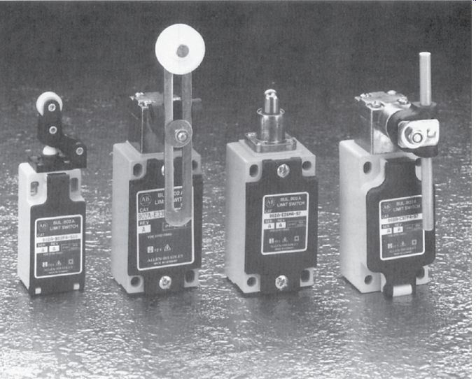
FIG. 7 Styles of contact style limit switches.
Along with the evolution of the motor starter in the use of electronics for the control of power is the evolution of the sensor industry to feed signals to the controllers. The controllers may be programmable controllers (PC), which in turn supply a signal to an electromechanical starter or to an electronic controller. Whatever finally controls the motor speed and direction needs sensory input from the real world. These inputs can be light, heat, pressure, proximity, sound, or any other sense that starts some predetermined sequence of operation for the motor. Sensors now can be electronic rather than electromechanical in many cases. The limit switch, which has a feeler or roller as in FIG. 7, can be replaced by an inductive or capacitive sensor, which does not require physical contact to sense an object's presence.
Proximity Sensors--Proximity sensors (controls) are available in two types: inductive sensors and capacitive sensors. A typical inductive sensor is an electronic circuit type of sensor that produces a small magnetic field at a radio frequency (RF). As the magnetic waves are produced, a tuned circuit is set to react to an altered oscillation created by a detected metal object. The tuning of these circuits is adjustable to account for the distance of detection and the amount of metal that is required before sensing is accomplished. As a metal object approaches the inductive proximity sensor, the magnetic coil in the sensor actually induces eddy currents into the detected target. This causes a change in the RF oscillations, and the amplitude on the RF is reduced or dampened. This dampened signal is detected by the driving electronics and switches the proximity sensor output to an "on," or dampened, state. As the object moves away from the sensor, the oscillator output returns to the un-dampened state, which allows the output to turn off.
Inductive proximity sensors work well in dirty or greasy environments where photo sensors do not work well. They have very fast response and can detect lightweight objects that cannot be detected by mechanical limit switches. Inductive sensors also can be used to detect metal objects behind nonmetallic materials such as glass or plastic. The two drawbacks to an inductive sensor are that the target to be detected must be metal, and the distance of detection is limited to approximately 4 in. The output of these sensors can be a relay contact or other type of output desired for the associated control circuitry (see FIG. 8).
Capacitive sensors work because of the effects of different materials on the dielectric constant of a capacitive device. Various nonmetal materials have different dielectric constants. As a material is sensed by a capacitive sensor, the dielectric constant of the circuit changes and starts an oscillation that is detected by the receiver. This altered condition initiates the electronics to cause an output relay to change state (open to closed, or vice versa).
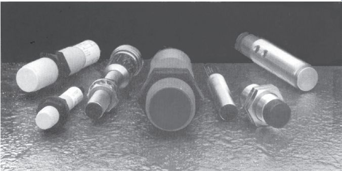
FIG. 8 Proximity sensors.
The capacitive proximity sensor has an advantage over the inductive sensor in that it can detect both nonmetallic and metallic objects. It has a larger sensing range and can be used for detecting liquid targets through nonmetallic barriers. It can be used for looking through glass or plastic tanks to detect liquid or other materials, such as plastic pellets in a feeder hopper.
The capacitive sensor has several limitations. It is more affected by moisture and humidity, and if embedded in the equipment, the surrounding material must be considered in the calibration. Also, because it has greater sensing range, more space must be maintained between sensors, and the target area must be well defined (see FIG. 9).
Many types of sensors as well as many types of pilot devices are available. All are intended to provide input information to control electrical systems. Up to this point, we have only discussed simple on-off control schemes where the pilot device is the decision point to energize or de-energize a motor starter. If more complex controls are needed with many different inputs controlling many different output functions, another decision maker may be needed, such as a programmable controller.
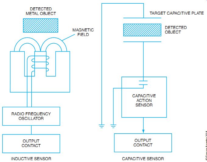
FIG. 9 Simplified diagrams of inductive and capacitive proximity sensors.
Photoelectric Controls
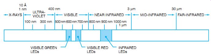
FIG. 10 Light spectrum of photoelectric sensors.
Photoelectric sensors have a wide variety of methods to detect an object. Other than mechanical actuation, other types of sensors are also used. Photoelectric controls are used where physical contact is not needed or desired. Photoelectric control covers a broad spectrum of controls.
The light used is not always visible. The light may be anywhere in the light spectrum from ultraviolet at one end to infrared at the other (see FIG. 10).
The methods of gathering or sensing the light also may vary. Photoelectric controls use a variety of devices to detect the presence or absence of light.
Photodiode sensors are light-activated sensors with a semiconductor diode that uses a clear covering for the diode case. Because the diode is operated in reverse bias, it does not allow current to flow in the circuit when no light is striking the transparent case. However, as light energy increases on the diode, current is allowed to flow in the circuit. This, in turn, controls a transistor to provide the switching needed in the circuit.
Photoresistive cells (or photoconductive cells) also are used. Often the concept used in photoelectric control is employed to monitor surrounding daylight conditions and control out door lighting. When light strikes the photoresistive cell, the resistance of the device drops and allows a larger current to flow. The resultant current flow often picks up a relay (electronic relay) to provide the desired switching result. A cadmium sulfide cell (cad cell) is used because the resistance changes from approximately 50 ohms in direct sunlight to many thousands of ohms when dark.
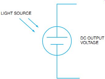
FIG. 11 Photovoltaic cell produces DC output voltage when struck by light.
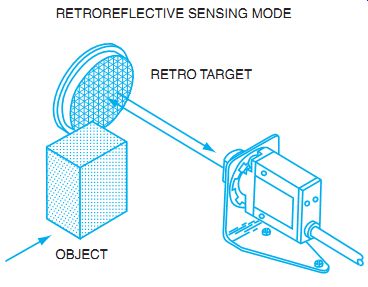
FIG. 12 Retroreflective sensor uses a light source and a reflective target.
Object to be sensed is between sensor and reflector.
When used in conjunction with more electronic circuitry, the switching point of the relay can be changed to reflect a desired light level control. Older types of photocells often used a metal hood to cover the cad cell. This allowed control of the amount of light on the cell and allowed adjustment of the activation point.
Caution: When installing photocells to control lighting based on available (ambient) light, make sure the cell faces away from the light source you are controlling. Otherwise, as dusk arrives (and you want to turn on the outdoor lighting), the cad cell looking at the light source turns off the lights it just turned on. The result is blinking lights that go on and off all night.
Photovoltaic cells are sometimes also used. As the name implies, the cell actually creates or generates a voltage as the light strikes the cell. Current silicon photovoltaic cells (solar cells) produce approximately 0.5-volt DC at 150 mA for each square inch of cell area. The symbol in FIG. 11 indicates that the cell actually produces a DC voltage and is useful where an external voltage source may not be convenient.
Sensor style and technique are different based on the type of sensor and application. Photosensors that use their own internal light source rather than ambient light use one of several styles of reflection techniques to "see" the light source. The items to be seen, the physical space, and the surrounding light help determine which reflective technique should be used.
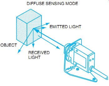
FIG. 13 Diffuse mode sensor with source and receiver in the same housing.
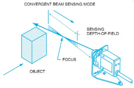
FIG. 14 Convergent beam sensor. Light is focused at a specific point
where the object is sensed.
Retroreflective scan sensors use a light source and receiver mounted in the same enclosure.
The light is directed toward a reflective surface such as a common bicycle type of reflector (see FIG. 12). The reflected light is detected by the receiver and in turn picks up a relay. Often these devices can be arranged to pick light or pick dark. Pick light means the relay is energized with a completed light beam. Pick dark means the relay is picked up when the light beam is obstructed and the light is not reflected.
Retroreflective sensors are a good style to use when you have room for a reflector and the object to be sensed is not reflective itself. In addition, the alignment is not critical, so some vibration of the scanner or reflector is tolerated. The typical distance limit to the target reflector is approximately 40 ft. One advantage of the retroreflective type of sensor is that all wiring is to one device with a nonelectrical reflector placed where convenient.
Retroreflective scan also could be used to count objects that have reflective tape applied. As the objects move past the sensor, the reflected light causes a con tact closure in the retroreflective sensor.
Diffuse scan sensors use the principle of a light source directed at the surface of objects that are not reflective. Most of the light source is absorbed by the object, and the rest is diffused in all directions. A receiver is placed at about the same distance from the surface as the light source.
The small amount of light that is returned to the receiver indicates presence of the object. Most diffuse scan sensors use a lens to collimate, or make the light rays parallel, so that the receiver can receive more returned light. These sensors are used in close proximity to the object to be detected (see FIG. 13).
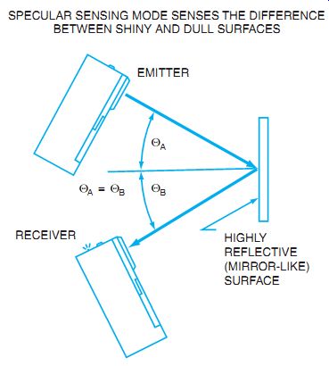
FIG. 15 Specular scanner uses an emitter and receiver to sense objects
with shiny surfaces. SPECULAR SENSING MODE SENSES THE DIFFERENCE BETWEEN SHINY
AND DULL SURFACES ; HIGHLY REFLECTIVE (MIRROR-LIKE) SURFACE
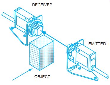
FIG. 16 Direct scan or opposed sensing uses an emitter and receiver to
detect an object between them.
A convergent beam is used to detect objects that are near other reflective surfaces, or for scanning small objects (see FIG. 14). Convergent beam sensors use the light source and sensing device in a single head. The light beam is focused or converged at the object to be sensed. This is a fixed distance determined by the sensor and is adjustable by field focus controls. If the object is not at the focal point of the beam, no light is reflected back to the receiver.
If an object is at the focal point (not in front of or behind the focal point), a small amount of light is reflected to the receiver. Only one head is used and the surrounding surfaces are ignored. Convergent beam sensors are ideal where the objects are near other surfaces or where the objects have low reflectivity.
Specular scan sensors use a light source and a receiver mounted at angles to each other, as in FIG. 15. The principle is to use a reflected light beam off a shiny object. The focal point is set to reflect light from the light source to the receiver. If an object interferes with that reflection, the receiver "sees" the object. Another option is for the object to complete the reflected beam.
By adjusting the angle of reflection, a shiny object can cause the beam to be reflected back to the receiver to "see" the object. Mounting angles are very precise, and a lot of vibration is not tolerated.
The least complicated sensor is called direct scan. This method uses a transmitter (light source) and a receiver, as shown in FIG. 16. If an object passes between the transmitter and receiver, the beam is broken and the object is detected. Alignment is critical in the sensors, and wiring is required to both the transmitter and receiver. Direct-scan sensors are harder to keep in alignment, but they are used extensively.
Many light sources use visible light, but the options include ultra violet light and infrared light. When sources other than visible light are used, aids are required to help set up, aim, and troubleshoot the devices. To determine whether an infrared light source is emitting, a small portable receiver is used to detect light output. If the light receiver is suspected to be defective, a portable light source can be used to transmit a known beam to the receiver. After that, troubleshooting regarding focus, improper application, or replacement of the defective device can proceed.
Fiber optics are also used to sense objects. Light is transmitted through a fiber-optic cable to the point where an object is to be detected. This allows the sensor to be located out of the way, and only the small cables have to be installed at the sensing location. Bifurcated fiber-optic cable uses the same fiber bundle to send and receive light (see FIG. 17). A "thru" scan has a transmitter and receiver cable as separate cables.
Be sure to check the manufacturer's specifications when determining the proper photo electric device to use. Specific application is important. Ambient light, temperature, vibration, moisture, and surrounding dust are all important considerations.
Strain gauges sense pressure and therefore can measure weight. An electronic strain gauge is typically made up of resistive components built into a wheatstone bridge configuration. The four parts of the bridge are shown in FIG. 18. By bonding the semiconductors to a pressure-sensitive diaphragm, a change in expansion or contraction causes the resistance of the semiconductor to change. With a supply voltage applied, the output voltage is proportional to the change of the bridge resistance. With no pressure applied, the output is zero volts. As the pressure on the electronic elements changes, two of them increase resistance, and the other two decrease resistance. The output voltage proportionally changes to measure compression. The analog output voltage can then be sent to a monitor or controller to initiate some action. These strain gauges often have temperature stabilizers and offset adjustments to allow for calibration.
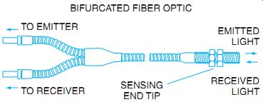
FIG. 17 Bifurcated cable can be used in opposed mode. It uses fiber optics
to bring light from the sensor head to the application.
Temperature detection for industrial control is usually done through thermistors or resistive temperature detectors (RTDs). Thermistors are resistors that change resistance due to thermal effects, known as thermal resistors (shortened to thermistors). If the thermistor has a negative temperature coefficient, it means that as the temperature of the semiconductor rises, the resistance has a negative effect, or decreases (noted as NTC in FIG. 19). If the resistance were to rise with an increase in temperature, the component would have a positive temperature coefficient. The resistors can be used directly in a circuit, which changes current flow as the resistance changes, or can be placed in a bridge much like a strain gauge to control an output voltage.
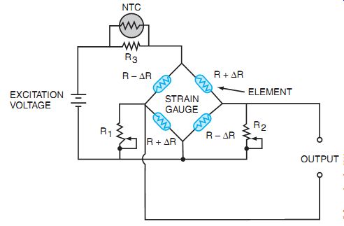
FIG. 18 A semiconductor strain gauge configuration.
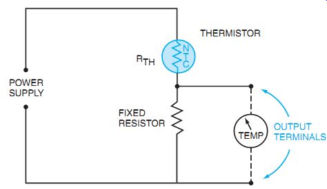
FIG. 19 Basic thermistor temperature detector circuit.
An RTD typically uses metals that exhibit a positive temperature coefficient. Nickel and platinum are commonly used as the metals in the RTD sensing point. Nickel is used to sense temperature because it has a large change in resistance with small changes in temperature.
Platinum is used when the temperature variations are large and therefore the ratio of the temperature to change of resistance is large. The RTD assembly is usually encased in a sensor style, and only the connection leads are available for connection.
IEC STANDARDS
To compete in the world market, U.S. manufacturers must produce goods that meet the technical and consumer requirements of other countries. The emphasis in Europe, for example, has been to produce electrical products that are more specific to need. This reduces the usage range and the amount of materials needed for the starter. Although customers of such products do not pay for more than they need, the products are not as rugged under adverse conditions.
The International Electrotechnical Commission (IEC), headquartered in Geneva, Switzerland, is a counterpart to the National Electrical Manufacturers Association (NEMA). IEC standards can be used to select the most suitable controller. The IEC philosophy is that utilization is a critical part of the selection process. The user must choose the utilization category, and then select a product in that category that fits the need. In addition, the user must check to determine if the manufacturer's contact life rating is adequate for the purpose. Typical utilization categories are presented in FIG. 20. Contact life is also taken into account. To make the proper selection, use the proper application selection graphs, as shown in FIG. 21.
The horizontal axis (Ie) in FIG. 21 represents the operational current that the power contacts must handle. The vertical axis represents the number of operating cycles that can be expected in the contactor life. Read along the Ie axis to the point of the normal full-load current,
----------------
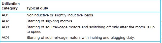
FIG. 20 Utilization list for typical duties of IEC starters.
Common Utilization Categories for AC Contactors Utilization category Typical duty AC1 Noninductive or slightly inductive loads AC2 Starting of slip-ring motors AC3 Starting of squirrel-cage motors and switching off only after the motor is up to speed AC4 Starting of squirrel-cage motors with inching and plugging duty.
Note: In an AC3 application, the contactor will never interrupt more than the motor's full-load current. If the application requires interruption of current greater than motor FLC, it is an AC4 application.
----------------
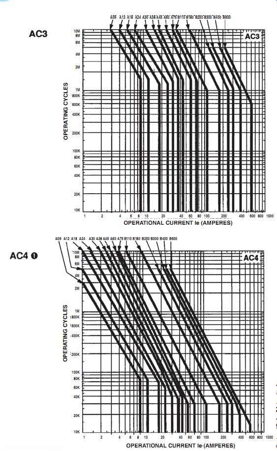
FIG. 21 Use of charts in utilization categories helps in selection of
the proper starter.
Note that the AC4 life load curves are based on the assumption that motors used have a locked rotor current equal to or less than 600% of motor full-load current.
and then up to the point a particular contactor crosses the current line. Reading horizontally over to the left supplies the projected number of operations. For example, the AC3 category is for starters that control squirrel-cage motors and that switch off only after the motor is up to speed. A 5 hp, 460-volt, three-phase motor draws 15.2 amperes according to NEC Table 430.250. Using this data, read 15.2 amperes on the Ie axis. Read straight up to where the bold line crosses the A18 vertical line. Contactor A18 would provide approximately 1.5 million operations. If that does not seem sufficient, go up to the A24 bold line crossing the 15-ampere vertical line. An A24 may provide 3 million operations.
Certain considerations must be taken into account when selecting NEMA or IEC standards for installations. How much expertise do you need to make the proper selection? Do you want to dedicate the increased space usually needed for NEMA controllers? Do you have a good understanding of the application? If you are replacing an existing installation, what other components have to be changed? How much is cost a factor compared to interchangeability? Are overloads adjustable or changeable? These questions, along with the difference in price, must be considered when determining the proper selection.
SUMMARY
The advancement of electronics into the control of electrical high-power equipment has many facets. From the measurement of the real world and the collection of measurements, the information can be sent to control the power circuits of large motors through the use of high-power transistors. To correctly design, build, test, or troubleshoot a complex system, a solid knowledge of all the various components is necessary. To properly retrofit a failed system or diagnose problems in a malfunctioning system, a working knowledge of terminology and capabilities is necessary. Solid-state drives have many applications and in many cases can replace obsolete mechanical control systems. Solid-state pilot devices can also be used to resolve some of the toughest sensor problems.
QUIZ
A. Answer the statements and questions in items 1 through 7.
1. When one of the three phase conductors to a motor is disconnected, the condition that results is known as ___ _____.
2. Name two of the fault conditions that can often be detected by electronic drives.
3. Are motor ramp-up times always equal to motor ramp-down times? Explain.
4. A flux-vector drive has (better/worse) speed control than a standard PWM drive.
(Circle the correct answer.)
5. Name two types of proximity sensors.
6. What does RTD stand for? ____
7. What are the two vector components that are measured to make a vector drive effective?
B. Select the correct answer for the following statements, and place the corresponding letter in the space provided.
8. When programming a drive, the service factor must be known. SF of 1.0 means that the motor _____
a. is rated for 1 hp.
b. has a safety factor of 10 times the normal load.
c. cannot be overloaded.
d. needs to be serviced once per year.
9. PWM drives are actually electronic drives that output _____
a. true sinewaves.
b. an equivalent sinewave.
c. six-step AC wave approximations.
d. DC positive wave magnetics.
10. Strain gauges are used to measure
a. temperature at a junction.
b. relative tension between electrical signals.
c. the pressure of compression or extension.
d. the thickness of metal at the point of fatigue.