AMAZON multi-meters discounts AMAZON oscilloscope discounts
GOALS:
• describe the basic sequence of actions of the following types of controllers when used to control three-phase AC induction motors:
• jogging controller
• quick-stop AC controller (plugging)
• dynamic braking controller
• resistance starter controller
• automatic autotransformer compensator
• automatic controller for wound-rotor induction motors
• wye-delta controller
• automatic controller for synchronous motors
• identify and use the various National Electrical Code sections pertaining to controllers and remote-control circuits for motors.
• state why AC adjustable speed drives are used.
• list the types of adjustable speed drives.
• describe the operating principles of various AC adjustable speed drives.
• describe the basic controls used for medium- voltage motors.
• list the advantages and disadvantages of selected units.
The industrial electrician is required to install, maintain, and repair automatic AC controllers that start up and provide speed control for squirrel-cage induction motors, wound-rotor induction motors, and synchronous motors.
MOTOR CONTROLLERS WITH JOGGING CAPABILITY
Many industrial processes require that the driven machines involved in the process be inched or moved small distances. Motor controllers designed to provide control for this type of operation are called jogging controllers. Jogging is the quickly repeated closure of a controller circuit to start a motor from rest for the purpose of accomplishing small movements of the driven machine.
An across-the-line (ATL) magnetic motor switch may be used to provide jogging control if the proper type of pushbutton station is used in the control circuit. Such a pushbutton station is called a start-jog-stop station.
FIG. 1(A) is a diagram of the connections for a three-phase AC induction motor connected to a jogging, ATL motor-starting switch.
FIG. 1(B) shows the starter with the cover removed. Note in FIG. 1 that the connections and operation of the start and stop pushbuttons are the same as those for a standard pushbutton station with start and stop positions. The connections for the jog pushbutton, however, are more complex and should be studied in detail. When the jog pushbutton is pressed, coil M is energized, main contacts M close, and the motor starts turning. The small auxiliary contacts M also close, but do not function as a sealing circuit around the jog pushbutton because pushing the jog pushbutton also opens the sealing circuit. As a result, as soon as the jog pushbutton is released, coil M is de-energized and all M contacts open. Before the jog pushbutton returns to its normal position, the sealing M contacts open and thus the control circuit remains open. This control also can be used for standard start-stop operations. In summary, then, repeated closures of the jog pushbutton start the motor momentarily so that the driven machine can be inched or jogged to the desired position.
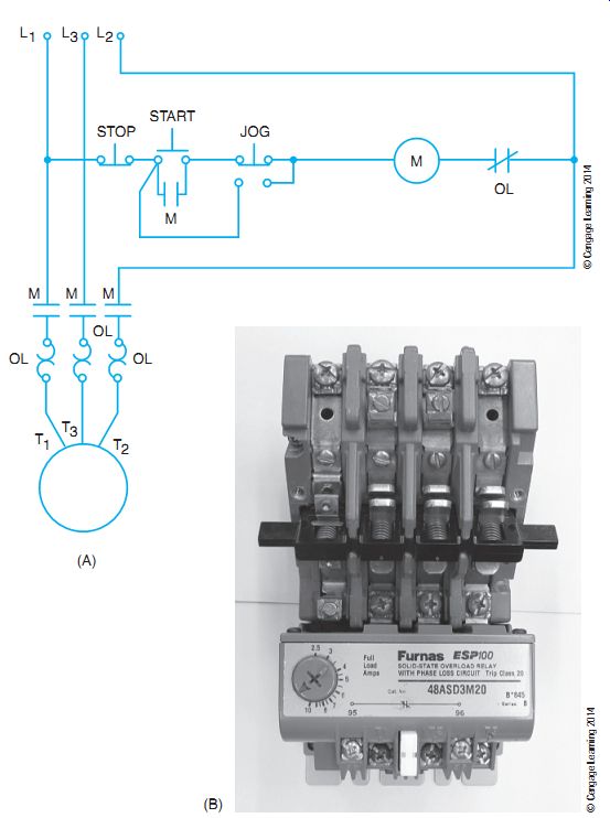
FIG. 1 (A) Elementary diagram connections for a three-phase motor with
jogging. (B) Magnetic starter with cover removed-exposing contacts.
QUICK-STOP AC CONTROLLER (PLUGGING)
Some industrial applications require that three-phase motors be stopped quickly. If any two of the line leads feeding a three-phase motor are reversed, a countertorque is set up that brings the motor to a quick standstill before it begins to rotate in the reverse direction. If the circuit is interrupted at the instant the motor begins to turn in the opposite direction, the rotor just stops. This method of bringing a motor to a quick stop is called plugging. The motor controller required to provide this type of operation is an ATL magnetic motor starter with reversing control and a special plugging relay. The plugging relay may be belt driven from an auxiliary pulley on the motor shaft, or attached to a through-shaft motor.
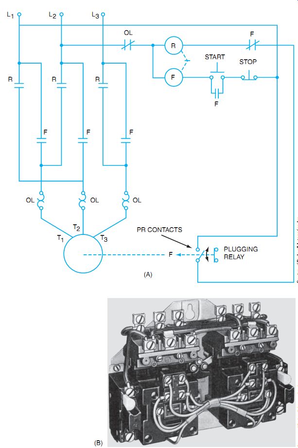
FIG. 2 (A) Elementary circuit with a plugging relay. (B) AC full-voltage
reversing starter, size 1.
The connections for a quick-stop AC controller are shown in FIG. 2(A). The controller itself is shown in FIG. 2(B). When the start pushbutton is pressed, relay coil F is energized. As a result, the small, normally closed F contacts open. These contacts are connected in series with the reverse coil, which locks out reverse operation. In addition, the other small, normally open F contacts close and maintain the start pushbutton circuit. When the start but ton is released, the circuit of coil F is maintained through the sealing circuit, main F contacts close, and the rated three-phase voltage is applied to the motor terminals. Then the motor comes up to speed, and PR contacts of the plugging relay close.
When the stop pushbutton is pressed, the F relay coil is de-energized. As a result of this action, the main F contacts for the motor circuit open and disconnect the motor from the three phase source. In addition, the small F holding contacts open, which de-energizes the holding or sealing circuit around the start pushbutton. Finally, the small F contacts in series with the reverse relay close to their normal position, and the reverse relay coil is energized.
The main R contacts now close to reconnect the three-phase line voltage to the motor terminals. The connections of two line leads are interchanged. The resulting reversing counter torque developed in the motor brings it to a quick stop. At the moment the motor begins to turn in the reverse direction, PR contacts open due to the mechanical action of the PR relay unit.
Coil R is de-energized and the R contacts open and interrupt the power supply to the motor.
Because the motor is just beginning to turn in the opposite direction, it comes to a standstill.
The motor supplies the mechanical power to drive a disk that causes PR contacts to close when the motor is in operation.
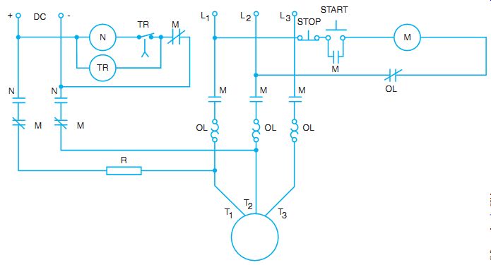
FIG. 3 A circuit for dynamic braking of an AC motor.
DYNAMIC BRAKING WITH INDUCTION MOTORS
From the study of DC controllers, we know that dynamic braking is a method used to help bring a motor to a quicker stop without the extensive use of friction brakes. In this application, dynamic braking means that the motor involved is used as a generator. An energy-dissipating resistance is connected across the terminals of the motor after it is disconnected from the line.
Dynamic braking also can be applied to induction motors. When the stop pushbutton is pressed, the motor is disconnected from the three-phase source, and the stator windings are excited by a DC source. A stationary magnetic field is developed by the direct current in the stator windings. As the squirrel-cage rotor revolves through this stationary field, a high rotor current is created. This rotor current reacts with the stationary field of the stator to produce a countertorque that slows and stops the motor.
FIG. 3 is a diagram of an AC motor installation with an across-the-line magnetic motor starter and dynamic braking capability.
When the start pushbutton is pressed, coil M is energized. At this instant, the main M contacts close and connect the motor terminals to the three-phase source, and the auxiliary, normally open M contacts close and provide a maintaining circuit around the start pushbutton. When relay coil M is energized, the normally closed contacts M in the DC control circuit open, with the result that both the main DC relay coil N and the time-delay relay coil TR are de-energized, and interlocks in the DC circuit open. The three-phase voltage applied to the motor terminals causes the motor to accelerate to the rated speed.
When the stop pushbutton is pressed, coil M is de-energized. At this moment, a number of actions occur: (1) The main contacts M open and disconnect the motor from the three-phase source; (2) the auxiliary M contacts open (these contacts act as a maintaining circuit); (3) M protective interlocks in the DC circuit close; and (4) the auxiliary, normally closed M contacts in the DC control circuit close and energize the time-delay relay and the main relay coil N. Energizing relay coil N causes the closing of the N contacts so that DC voltage is connected on the AC windings through a current-limiting resistance. As a result, the motor comes to a quick stop. Following a definite period after the motor has stopped, measured in seconds, the TR relay coil operates and opens the TR contacts to cause coil N to become de-energized.
Thus, the N contacts open and disconnect the motor windings from the DC source. The controller now is ready for the next starting cycle.
Timing contacts are shown in their de-energized condition. Timers are either on delay or off delay and are used in motor control work. The actual timer mechanism varies depending on the vintage of the controller and the manufacturer. See section 10 for a complete description of the timer symbols and operations.
RESISTANCE STARTER CONTROLLER
When a squirrel-cage induction motor is connected directly across the rated line voltage, the starting current may be 300% to 600% or more of the rated current of the motor. In large motors, this high current may cause serious voltage regulation problems and overload industrial power feeders.
The starting current of a squirrel-cage induction motor can be reduced by using a resistance starter controller. This type of controller inserts equal resistance values in each line wire at the instant the motor is started. After the motor accelerates to a value near its rated speed, the resistance is cut out of the circuit and full line voltage is applied to the motor terminals.
FIG. 4(A) shows a diagram of the circuit connections for a resistance starter. A photo of this starter is shown in FIG. 4(B). When the start button is pressed, main relay coil M is energized. The main contacts close and connect the motor to the three-phase source through the three resistors (R). The circuit for coil M is maintained through the small auxiliary contacts (3 and 4), which act as a sealing circuit around the normally open start pushbutton.
When the main contacts of relay coil M are closed, a timing relay is energized. The on-delay timer closes contacts 4 to 5 after a set time. After a predetermined time elapses, the definite time contacts close and energize coil R. Coil R causes three sets of contacts to close and shunt out the three resistors. Thus, the motor is connected directly across the rated line voltage with no interruption of the power line (closed transition).
When the stop button is pressed, the circuits of both coil M and coil R are opened. This causes the opening of the main contacts, the sealing contacts, and the contacts that shunt the series resistors. As a result, the motor is disconnected from the three-phase source.
The motor starting current in the resistance starter causes a relatively high voltage drop in the three resistors. Because of this, the voltage across the motor terminals at starting is low.
As the motor accelerates, the current decreases; the voltage drop across the three resistors decreases; and the terminal voltage of the motor increases gradually. A smooth acceleration is obtained because of this gradual increase in the terminal voltage. However, it may be unwise to select resistance starting for many starting tasks because of the energy dissipated in the starting resistors.
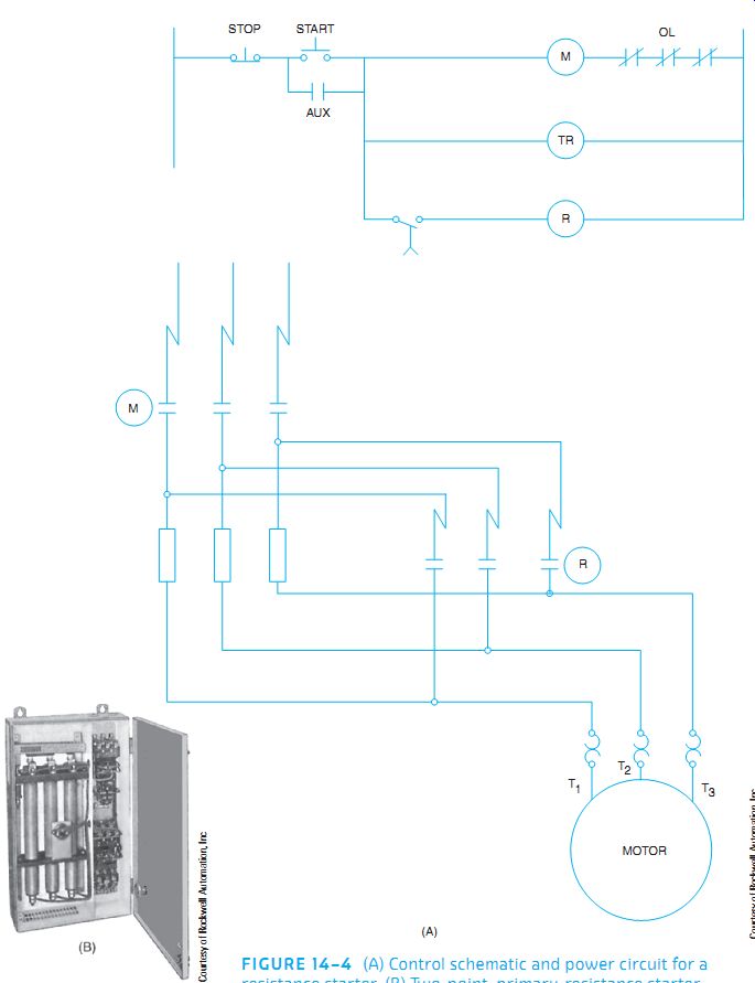
FIG. 4 (A) Control schematic and power circuit for a resistance starter.
(B) Two-point, primary-resistance starter rated at 25 hp, 600 volts.
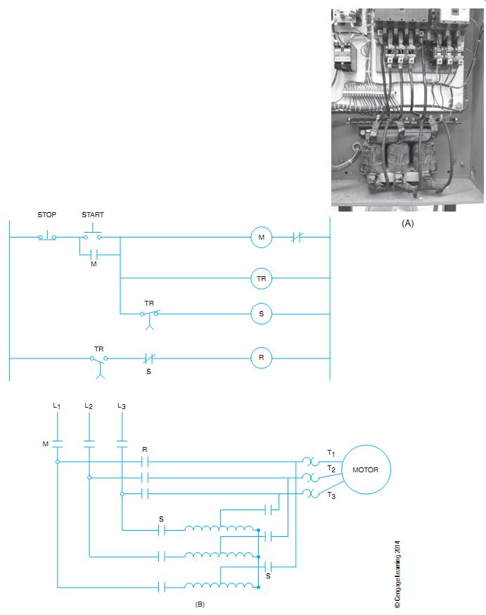
FIG. 5 (A) Reduced voltage starter, autotransformer type. (B) Control
schematic and power circuit for autotransformer type of starter.
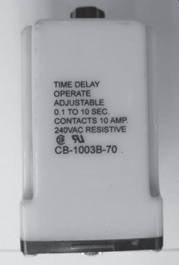
FIG. 6 An AC on-delay timer that provides time delay after the coil is
energized.
AUTOMATIC AUTOTRANSFORMER COMPENSATOR
An automatic compensator is used to automatically connect an autotransformer in series with the motor during the starting cycle (FIG. 5). A compensator is another name for an autotransformer starter. By inserting an autotransformer, the voltage to the motor is reduced, and therefore the starting current is reduced. The starting current drawn from the line is reduced. Because the autotransformer steps down the voltage to the motor, the secondary (motor) current is higher than the primary current. The result is that the cur rent drawn from the line is much less than if the motor were started with a reduced voltage through a resistor. The automatic compensator can be pushbutton controlled from a convenient location. FIG. 5(B) shows a typical schematic wiring diagram for an automatic autotransformer compensator.
When the start button is pressed, a circuit is established from power line 1 through the following devices to power line 2: through the stop button and the depressed start button to energize the M coil on control line 1 and the timing relay coil on control line 3 and through the TR timer contacts on line 4 to the S coil. The M auxiliary coil on line 2 closes and provides a holding circuit for the start button. With the M coil energized, the M power contacts close and the S power contacts close. This supplies power to the autotransformer, and a reduced voltage is supplied to the motor. As the TR timer times out, the TR contacts on line 5 close and the TR contacts on line 4 open. As the contacts on line 4 open, the S relay is de-energized and the S contacts on line 5 close to supply control power to the R relay. Now the power is disconnected from the autotransformer and supplied directly to the motor as full voltage (see FIG. 6).
AUTOMATIC CONTROLLER FOR WOUND-ROTOR INDUCTION MOTORS
Manual speed controllers, such as the faceplate type or the drum type, may be used to pro vide speed control for wound-rotor induction motors in industrial applications. If the resistance in the rotor circuit of a wound-rotor induction motor is to be used only on starting, then an automatic controller may be used (FIG. 7). In this case, resistors in the rotor circuit are automatically removed by contactors arranged to operate in sequence at definite time intervals.
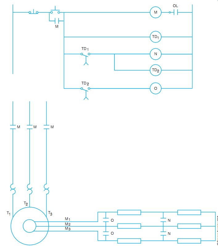
FIG. 7 Control schematic and power diagram for timed automatic controller
for wound-rotor motor.
As shown in FIG. 7, when the start button is pressed, the main relay coil M is energized. The main contacts are closed to connect the stator circuit of the motor directly across the three-phase line voltage. All the resistance of the controller is inserted in the secondary circuit of the motor as it begins to accelerate.
When the start pushbutton is released, the M coil auxiliary contact holds the M coil in, and power is applied to the motor primary windings marked T1, T2, and T3. The first timer begins timing at the same instant the M coil is energized. After a predetermined time, timer 1 times out and closes the contacts on the next line, thereby energizing the N coil. This pulls the N power contacts closed and shunts some of the resistance in the rotor secondary. As the N coil is energized, the second timer, TD2, is started. After another predetermined time, TD2 times out and closes, energizes the O coil, and pulls the remaining power contacts closed to shunt all the secondary rotor resistance. Examples of timing relays appear in FIG. 8 and FIG. 9.
When the stop pushbutton is pressed, relay coil M is de-energized, and contacts M open to disconnect the motor from the line. Coil O also is de-energized, and contacts O open, with the result that all resistance is inserted in the rotor circuit for the next starting cycle.
Wound-rotor motors are also controlled by electronic controllers. Often these motors used electromechanical controllers to place resistance into the secondary rotor circuit to control inrush current and then to control speed. With automatic controllers, these motors can be retrofitted to use electronic soft-start control to bring the motor up to speed with a minimum inrush current. If additional speed control is needed, the controller still can insert power resistors into the secondary rotor circuit. The more resistance inserted, the slower the speed of the motor.
National Electrical Code regulations for wire size, starting overload protection, and running overload protection apply to both manual speed controllers and automatic controllers used with wound-rotor induction motors.
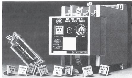
FIG. 8 Solid-state timing relays with various plug-in program keys.
WYE-DELTA CONTROLLER
FIG. 10(A) shows a simple method by which a three-phase, delta-connected motor can be started on reduced voltage by connecting the stator windings of the motor in wye during the starting period. FIG. 10(B) shows the actual starter. After the motor accelerates, the windings are reconnected in delta and placed directly across the rated three-phase voltage.
When the Start button is pressed, the main M contacts close, and relay coil Y and time delay relay TR are energized. Coil Y causes contacts Y to close, and the windings of the motor are connected in wye. If the line voltage is 230 volts, the voltage across each winding is 230 1.73 = 133 volts
The voltage across each winding is only 58% of the line voltage when the windings are connected in wye at the start position. (See three-phase voltage in Electricity 3, Guide 8.) After a definite period of time, the time-delay relay TR opens the circuit of relay coil Y, the Y contacts open, and the Y interlocks close.
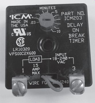
FIG. 9 Small solid state timers can provide many functions such as "on-delay".
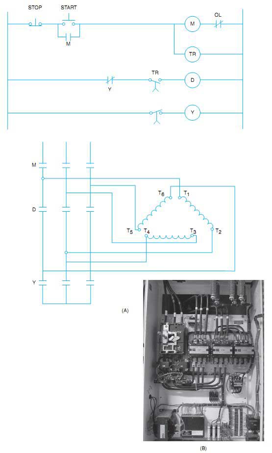
FIG. 10 (A) Control schematic and power diagram for wye-delta starter
with open transition. (B) Photo of a wye-delta, 200 hp closed transition.
The time-delay relay TR then closes the circuit of relay coil D (delta). All D contacts are closed, and the motor winding connections are changed from wye to delta. Full line voltage is applied to the motor windings, and the motor operates at its rated capacity.
Motors started by a wye-delta controller must have the leads of each phase winding brought out to the terminal connection box of the motor. In addition, the phase windings must be connected in delta for the normal running position.
Note: The electrician should never attempt to operate a three-phase, wye-connected motor with this type of controller. This results in an excessive voltage applied to the motor windings in the run position when the windings are connected in delta by the controller.
Another method of controlling the wye-delta controller is to provide a way to change from the wye connection to the delta connection without completely disconnecting the motor from the power line. This method is called closed transition as compared to the previously described open transition. By using resistors in the power circuit, the transition can be made from wye to delta, as shown in FIG. 11. When the start button is pressed, the S coil on line 1 and the 1M coil on line 2 are energized, and the power is supplied to the motor, which is connected in the star pattern by the S power contacts. As the timer 1M closes, it energizes coil 1A on line 3 and resistors are connected into the power circuit of the motor for a brief time, and the S coil is de-energized, releasing the motor from the wye connection. As 1A timing contacts close on line 4, the 2M coil is energized and the resistors are effectively shunted out of the circuit.
When using closed transition, the small current fluctuation that occurs as the motor is briefly disconnected from the line may cause a voltage dip in the voltage supply as well as a fluctuation in the motor's developing torque. To reduce the voltage and current disturbance, closed transition is used. Note the fluctuations in FIG. 12.
COMPARISON OF REDUCED-VOLTAGE STARTING METHODS
The chart in FIG. 13, shows the advantages and limitations of the various methods of reduced-voltage/reduced-torque types of motor starting. The advantage of using the reduced voltage is to reduce the inrush current to the motor from the supply line, thereby reducing the voltage dips and disturbances to the facility's electrical system. The motor's normal starting torque is also reduced, which may be an advantage or disadvantage. The starting torque is reduced in proportion to the voltage reduction squared. If the voltage is reduced to 50%, then the torque is 0.52, or 0.25 = 25%. If the voltage is reduced to 80%, the torque is reduced to 64%. An advantage to reduced torque is that the driven machinery is not violently started from a stopped position to full-locked rotor torque. The disadvantage may be that there is not enough torque to start the load.
AUTOMATIC CONTROLLER FOR SYNCHRONOUS MOTORS
Synchronous motors may be started by an ATL magnetic motor starting switch, a manual starting compensator, or an automatic starting compensator. Dynamic braking may be provided by the controller.
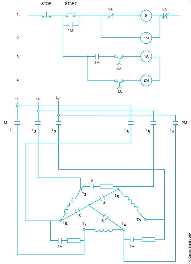
FIG. 11 Control schematic and power diagram for a wye-delta starter with
a closed transition.
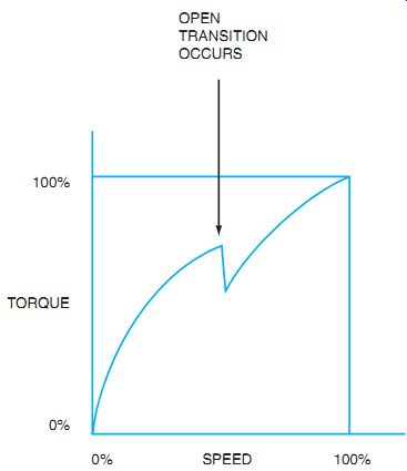
FIG. 12 Open transition speed torque curve shows a dip when transition
occurs.
FIG. 14 is a diagram of the connections for a synchronous motor controller with dynamic braking. When the start button is pressed, main relay coil M is energized. The four normally open M contacts close, and the two normally closed M contacts open. Three-phase voltage is applied to the motor terminals. When the motor accelerates to a speed near the synchronous speed, the DC field circuit is energized by secondary controls.
When the stop button is pressed, main relay coil M is de-energized. The M contacts open and disconnect the motor terminals from the three-phase line. The two normally closed M contacts reconnect the motor windings through the resistors, and the DC field remains energized.
As a result, the synchronous motor acts as an AC generator and delivers electrical energy to the two R resistors. The use of this type of controller results in a more rapid slowing of a synchro nous motor.
The National Electrical Code provides guidelines for branch-circuit fuse protection and running overload protection for branch circuits feeding three-phase synchronous motors, and for allowable conductor sizes for branch-circuit-feeding synchronous motors. Local building and electrical code authorities should be consulted before installations are made with motors and controllers that do not comply with National Electrical Code rulings.
------------------
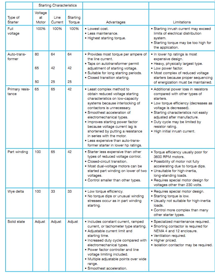
FIG. 13 Comparison chart for reduced-voltage starters.
------------------
--- SOLID-STATE REDUCED VOLTAGE STARTERS
Solid-state devices and equipment are used for reduced-voltage motor starting, electrical energy-saving control circuits, variable speed drives, motor protection, and other applications.
A motor starter consists of a control circuit, a motor power circuit, and protective devices for the wiring and the motor. The functions of a starter are performed by contactors and overload relays in electromechanical motor starters. In solid-state starters, the control functions are per formed by semiconductors. They are controlled by integrated circuits and microprocessors to provide the protective functions, operating instructions, and control.
Construction and Operation
The solid-state, reduced-voltage starter provides a smooth, stepless acceleration of a three-phase induction motor. This is accomplished by gradually turning on six power silicon-controlled rectifiers (SCRs). Two SCRs per phase are connected in a back-to-back or reverse parallel arrangement (FIG. 15). The SCRs are mounted on a heat (dissipating) sink to make up a power pole (phase). The SCRs are connected back to back so that they can pass AC and control the amount of voltage. Each power pole contains the gate firing circuits as discussed in Guide 11.
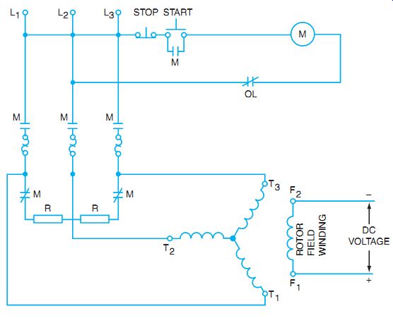
FIG. 14 Synchronous motor controller with dynamic braking.
SOLID-STATE REDUCED VOLTAGE STARTERS
Solid-state devices and equipment are used for reduced-voltage motor starting, electrical energy-saving control circuits, variable speed drives, motor protection, and other applications.
A motor starter consists of a control circuit, a motor power circuit, and protective devices for the wiring and the motor. The functions of a starter are performed by contactors and overload relays in electromechanical motor starters. In solid-state starters, the control functions are per formed by semiconductors. They are controlled by integrated circuits and microprocessors to provide the protective functions, operating instructions, and control.
Construction and Operation
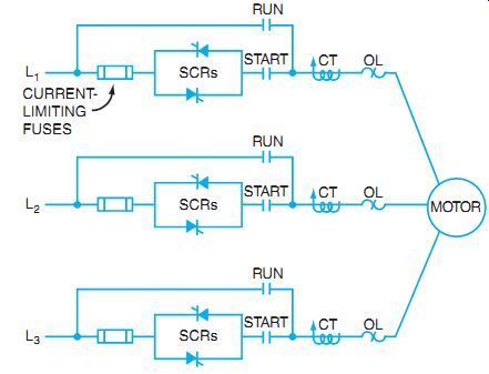
FIG. 15 Solid-state, reduced-voltage starter power circuit.
The solid-state, reduced-voltage starter provides a smooth, stepless acceleration of a three-phase induction motor. This is accomplished by gradually turning on six power silicon-controlled rectifiers (SCRs). Two SCRs per phase are connected in a back-to-back or reverse parallel arrangement (FIG. 15). The SCRs are mounted on a heat (dissipating) sink to make up a power pole (phase). The SCRs are connected back to back so that they can pass AC and control the amount of voltage. Each power pole contains the gate firing circuits as discussed in Guide 11.
An integrated thermal sensor is also provided to de-energize the starter if an over-temperature condition exists.
The firing circuitry on each power pole is controlled by a logic module. These modules monitor the starter for correct start-up and operating conditions. Some motor starters provide a visual indicator of the starting condition through the use of light-emitting diodes (LEDs).
The current-limiting starter is a common type that is designed to maintain the motor current at a constant level throughout the acceleration period. A current-limit potentiometer adjustment is provided to preset this current. A starter with current ramp acceleration is designed to begin acceleration at a low current level and then increase the current during the acceleration period.
As indicated in FIG. 15, this starter includes both start and run contactors.
The start contacts are in series with the SCRs; the run contacts are in parallel with the combination of SCRs and start contacts. When the starter is energized, the start contacts close. The motor acceleration is then controlled by phasing on the SCRs. When the motor reaches full speed, the run contacts close, and the motor is connected directly across the lines (closed transition). At this point, the SCRs are turned off and the start contacts open. Under full-speed running conditions, the SCRs are out of the circuit, eliminating SCR power losses during the run cycle. This feature saves energy; it also guards against possible damage due to overvoltage transients. With the starter in the de-energized position, all contacts are open, isolating the motor from the line. This open-circuit condition protects against accidental motor rotation as a result of SCR misfiring and/or SCR damage caused by overvoltage transients. A solid-state, reduced-voltage starter is shown in FIG. 16. Field connections are very similar to those for electromechanical starters.
Reduced Voltage Operation
To reduce the voltage applied to the motor in a solid-state starter, the SCRs can be turned on by the "gate" electrode for any desired part of each half cycle. Usually the SCRs turn off as the current wave reaches zero. They stay off until gated on again in the next half cycle. Some devices can vary the switching and timing. By switching the controlled current gating, the effective AC voltage can be varied to the motor. This voltage can be varied from zero to full voltage as required. The voltage is applied at some preset minimum value that can start the motor rotating. As the motor speed builds up, the SCR "on" time is gradually increased. The voltage is increased until the motor is placed across the line at full voltage. Mechanical shock is reduced, and the current inrush can be regulated and controlled as desired (FIG. 17). The solid-state, reduced-voltage starter can replace any of the electromechanical starters already described for reduced-voltage starting.
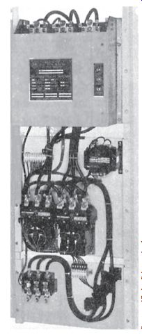
FIG. 16 Solid state, reduced-voltage starter power circuit.
CODE REFERENCES FOR MOTOR CONTROLLERS
The following sections of the National Electrical Code are concerned with motor controllers and remote control circuits.
1. 430.8 and 430.9 refer to the identification of motors and controllers with respect to controller nameplate ratings and terminal markings.
2. 430, Part III, is concerned with overload protection.
3. 430.37 provides the number of running overcurrent relays required for various electrical systems.
4. 430, Part IV, is concerned with branch-circuit, short-circuit, and ground-fault protection.
5. 430, Part VI, is concerned with controller circuits.
6. 430.81, Part VII, is concerned with motor controller installations.
7. 430.101, Part IX, covers motor disconnecting means.
FIG. 17 SCR controller section, the regulating part of the starter. The controller determines to what degree the SCRs should be phased on, thereby controlling the voltage applied to the motor.
AC ADJUSTABLE SPEED DRIVES
Adjustable speed drives have a flexibility that is particularly useful in specialized applications.
For this reason, these drives are widely used throughout the industry for conveyors used to move materials, hoists, grinders, mixers, pumps, variable speed fans, saws, and crushers. The advantages of AC drives include the maximum use of the driven equipment, better coordination of production processes, and reduced wear on mechanical equipment.
The AC induction motor is the major converter of electrical energy into another usable form. About two-thirds of the electrical energy produced in the United States is delivered to motors.
Much of the power that is consumed by AC motors goes into the operation of fans, blowers, and pumps. It has been estimated that approximately 50% of the motors in use are for these types of loads. Such loads are particularly appropriate to consider for energy savings. Several alternate methods of control for fans and pumps have been developed and show energy savings over traditional methods of control.
Fans and pumps are designed to meet the maximum demand of the system in which they are installed. Often, however, the actual demand varies and may be much less than the design capacity. Such conditions are accommodated by adding outlet dampers to fans or throttling valves to pumps. These controls are effective and simple but affect the efficiency of the system.
Other forms of control have been developed to adapt machinery to varying demands. These controls do not decrease the efficiency of the system as much as the traditional methods of control. One of the newer methods is the direct, variable speed control of the fan or pump. This method produces a more efficient means of flow control compared to other existing methods.
In addition to a tangible reduction in the power required to operate equipment and machinery resulting from the use of adjustable speed drives, other benefits include extended bearing life and pump seal life.
TYPES OF ADJUSTABLE SPEED DRIVES
Several types of variable speed drives can be used with wound-rotor induction motors. These drives are eddy-current (magnetic) drives, variable pitch drives, and adjustable-frequency drives.
Eddy-Current (Magnet) Drives
The eddy-current drive couples the motor to the load magnetically (FIG. 18). The electromagnetic coupling is a simple way to obtain an adjustable output speed from the constant input speed of squirrel-cage motors. No mechanical contact exists between the rotating members of the eddy-current drive; thus, there is no wear. Torque is transmitted between the two rotating units by an electromagnetic reaction created by an energized rotating coil winding. The rotation of the ring with relation to the electromagnet generates eddy currents and magnetic fields in the ring. Magnetic interaction between the two units transmits torque from the motor to the load. The slip between the motor and the load can be controlled continuously with great precision.
Torque can be controlled using a thyristor in an AC or DC circuit, or by using a rheostat to control the field through slip rings. When the eddy-current drive responds to an input or command voltage, the speed of the driven machine changes. A further refinement can be obtained in automatic control to regulate and maintain the output speed. The magnetic drive can be used with nearly any type of actuating device or transducer that can provide an electrical signal. For example, the input can be provided by static controls and sensors that detect liquid level, air and fluid pressures, temperature, and frequency.
Magnetic eddy-current drives are used for applications requiring an adjustable speed such as cranes, hoists, fans, compressors, and pumps (FIG. 19).
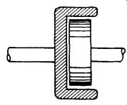
FIG. 18 Spider-rotor coil magnet rotated within a steel drum.
Variable Pitch Drives The speed of an AC squirrel-cage induction motor depends on the frequency (hertz) of the supply current and the number of poles of the motor. The equation expressing this relationship is
RPM = 60 × Hertz Pairs of poles
or
Synchronous speed (RPM) = 120 × Hertz Number of poles
A frequency changer may be used to vary the speed of this type of motor. A possible method is to drive an alternator through an adjustable mechanical speed drive.
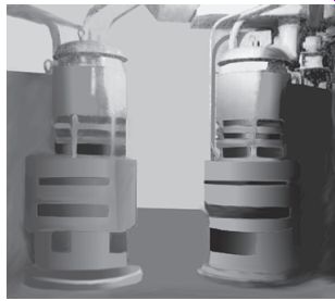
FIG. 19 Two magnetic drives driven by 100 hp induction motors mounted
on top.
The voltage is regulated automatically during frequency changes. An AC motor drives a variable cone pulley or sheave, which is belted to another variable pulley on the output shaft (FIG. 20). When the relative diameters of the two pulleys are changed, the speed between the input and the output can be controlled. As the alternator speed is varied, the output frequency varies, thereby varying the speed of the motor, or motors, connected electrically to the alternator supply.
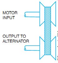
FIG. 20 Variable pitch pulley method of obtaining continuously adjustable
speed from constant motor speed shaft.
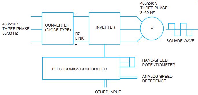
FIG. 21 Controller operation.
Adjustable Frequency AC Drives
Adjustable frequency (static solid-state) drives are also commonly called variable frequency drives (VFDs). The power conversion losses are greatly reduced when using these transistor controllers for adjustable speed drives. They are available in a range of horsepowers from fractional to 1000 hp. Adjustable frequency drives are designed to operate standard AC induction motors although "inverter duty" motors are more reliable when using a variable frequency input. This allows them to be added easily to an existing sys tem (FIG. 21).
Where energy saving is a major concern, the drives are ideal for pumping and fan applications. They are also used for many process control or machine applications where performance is a major concern. Many adjustable speed precision applications were limited to the use of DC motors. By using adjustable frequency controllers with optional dynamic braking, standard squirrel-cage motors can now be used in these applications. Municipal, industrial, commercial, and mining applications include sewage, waste water, slurry and booster pumps, ventilation and variable air volume fans, conveyors, production machines, and compressors.
AC VARIABLE SPEED/VARIABLE FREQUENCY CONTROLS
AC motors are designed to run at a specific full-load speed. This design speed takes into account various losses in the motor, including copper losses of the stator and the rotor and other losses such as iron losses, friction, and windage. The end result is some speed less than synchronous speed. Synchronous speed is calculated by the following formula:
Synchronous RPM = 120 × Frequency Number of poles
Use this formula to determine the synchronous speed of a motor if the number of poles and the applied frequency are known. The number of poles is usually fixed, and the frequency of a normal power feed in the United States is 60 Hz. Many other countries of the world use 50 Hz. as their standard frequency. Therefore, to operate an AC motor at other than its design speed, either the number of poles or the frequency must be altered. Some adjustable speed motors are able to reconnect the poles or connect a separate winding of poles to establish other set speeds. To vary the speed of an AC motor over a wide range of speeds, the applied frequency is altered.
There are two basic techniques for altering the frequency of the applied power through electronic means. Both techniques use the principle of rectifying the three-phase, AC, 60 Hz input power to a DC supply (see FIG. 22). The DC is then filtered to provide smooth DC to the inverter section of the electronic controller. The amplitude of the output voltage must change with the frequency, because at low frequency the impedance of the motor is low and the voltage must also be reduced to prevent overheating of the motor. Conversely, as the frequency is raised above 60 Hz, the motor's impedance is increased and voltage must also increase to maintain motor torque. This parameter of the controller functions is known as the volts per hertz ratio.
One method of speed control is the variable voltage inverter. The DC voltage applied to the inverter is adjusted, and then the pulse is modified to create various frequencies (see FIG. 21).
The other and more common method is known as pulse width modulation (PWM). The voltage output of the DC-to-AC inverter is really a series of DC pulses that is stepped to pro duce a "staircase" approximation of the sinewave at the frequency desired to control the motor speed. The controller uses a sensor and a set point to determine output frequency and the desired set speed.
The control modules adjust the output of a DC voltage-control module as it adjusts the output of the frequency-control module. The frequency-control module typically drives the output power controller. There are two output power controllers for each of the three phases: one controls the positive half cycles of one phase, and the other controls the negative half cycles of the same phase. Six output modules are required for three phases (FIG. 23).
When connected to a motor, the stepped output waveform appears close to a sinewave because of the motor's inductance. Frequency then determines the speed of the motor in conjunction with the set number of poles.
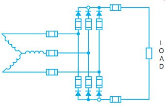
FIG. 22 Three-phase, full-wave rectifier with connected load.
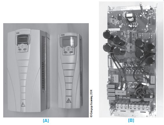
FIG. 23 (A) Three-phase 480V Variable frequency drive. (B) Electronic
circuit board inside a VFD.
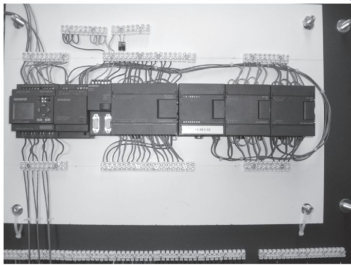
FIG. 24 PC with one I/O card removed.
INTRODUCTION TO PROGRAMMABLE CONTROLLERS
Modern motor control requires more exact timing and faster, more consistent operations than those provided by the older electromechanical relays and timers. Because modern manufacturing requirements also rely on system flexibility, a fast change system was needed that did not require extensive redesign, building, hand wiring, and testing to create a new motor control scheme.
Along with this change in needs, the microprocessor was improved to make it more reliable in industrial environments and more trouble-free in operation. The combination of these events produced the programmable logic controller (PLC).
Many versions of the PLC are made by various manufacturers and have various capabilities. However, all programmable controllers have at least three basic components. The first is a processor, which is a microprocessor that contains the instructions and makes the decisions.
The second component is an input/output section, which receives input information from the process it is controlling and connects it to the controller in the proper format. It also takes the output from the controller and interfaces to the real world of control devices. The third main component is the programmer. This is the operator's access to the controller. The programs are written in ladder-logic style, which is familiar to most electricians. This familiarity was the factor that allowed the PLC to be so widely accepted as a control system. Controls were easily converted and adapted by working electricians, without them having to learn extensive new microprocessor programming language.
PLCs are used where the control system is likely to be changed frequently and usually where there are multiple functions for the controller to monitor, compare, count, time, or operate. These conditions make the use of a PLC economical and practical.
Large control systems may have various input/output cards that must be coordinated according to the "field wiring," such as AC and DC voltage at various levels, transistor-transistor logic (TTL), input/output (I/O), analog I/O, thermocouple, or binary-coded decimal (BCD). FIG. 24 shows a PLC.
The intent of this guide is not to teach programming of the PLC, but to familiarize the electrician with the possibility of motor control using the PLC. Technician's Guide to Programmable Controllers, 5th edition, by Richard A. Cox (Delmar Cengage Learning, 2006) is an excellent reference to gain further generic information.
SUMMARY
Many methods are used to start, stop, jog, and reverse three-phase motors. The basic operations generally use a magnetic controller to supply power to the motor. The reversing controller is used in the plugging operation to momentarily reverse the power and therefore bring the motor to a quick stop. Dynamic braking can also be used to stop an AC motor by applying DC to the motor field. Various methods of reducing the starting current to the motor employ the application of reduced voltage at the motor terminals during the starting period. Resistance or reactance can be inserted in series with the motor to reduce the voltage. An autotransformer may be used to reduce the applied voltage. Wound-rotor motors use secondary resistors to keep the starting current to a minimum. Wye-delta starters can be used to reduce the starting current to the motor by changing the configuration of the connections. Solid-state starters are now being installed to reduce the inrush current and to control the speed and the stopping characteristics.
Variable frequency drives use electronics to control the frequency to the motor and therefore control the speed of the motor. Many motor-control schemes can be developed with the use of a PLC. This electronic equivalent of a relay system is used to provide exact timing and complex, but changeable, control through the use of a microprocessor-based system.
QUIZ
1. What is meant by the phrase jogging a motor?
2. What is meant by the term plugging?
3. How is dynamic braking applied to an AC induction motor?
4. How is dynamic braking applied to a synchronous motor?
5. Draw a schematic diagram of the connections for the control circuit of an ATL magnetic motor switch with jogging capability. Include the main relay coil; the pushbutton station with start, jog, and stop pushbuttons; and the sealing contactor.
6. What identifying information should appear on a motor controller so that the controller complies with the requirements of the National Electrical Code?
7. Draw a schematic diagram of an automatic controller used for a wound-rotor induction motor.
8. A three-phase AC induction motor has the following ratings: 15 hp, 230 volts, 42 amperes per terminal, 40° Celsius, and code classification F. In the spaces in the following table, insert the correct values for fuse protection and running overcurrent protection for this motor when used with each of the types of controllers listed.
9. What is the purpose of an automatic autotransformer starting compensator?
10. What is the purpose of an automatic controller used with wound-rotor induction motors?
11. A wye-delta controller starts the motor at ____
a. 173% of the line voltage.
b. 58% of the line voltage.
c. full line voltage.
d. 25% of the line voltage.
12. A three-phase, wye-connected motor _
a. should never be started by a wye-delta controller.
b. should always be started by a wye-delta controller.
c. can be started by a wye-delta controller if proper timers are used.
d. can be started by a wye-delta controller if proper pushbuttons are used.
13. How are SCRs connected to pass and control AC?
14. If a solid-state controller has contactors in the power circuit, in what position are the contacts of start and run in the off position? Why? _____
15. Why are adjustable speed drives used? _
16. List the types of AC adjustable speed drives.
17. How is the speed of the wound-rotor motor adjusted?
18. How is the eddy-current drive coupled to the load?
19. How is the AC frequency varied in the mechanical method drive?
20. What is the formula for calculating AC motor speed? ____
21. What basic devices are provided in the adjustable frequency drive?
22. With an apparent high degree of skill required to maintain an adjustable frequency drive control, how would a plant electrician quickly repair a defective unit?