AMAZON multi-meters discounts AMAZON oscilloscope discounts
[Note: various equations denoted by "e." are not yet avail., but coming soon.]
1. Calculation of Electrical Shock Using the Circuit Model of the Body
When electrical systems are being designed, the safety evaluation must include an assessment of the effect of human contact with any metallic or energized parts or conductors which may exist.
Whenever possible, grounding, insulation, and physical distance should reduce or eliminate the hazards of electrical shock. During the design, the effect of contact with conductors can be evaluated using electrical circuit models of the human body. There will be many factors which affect such a model, and varying degrees of complexity of the model depending on the application and the level of potential risk which may be present. This Section will present an introduction to this field, which is still evolving as new research is performed and more advanced mathematical modeling techniques are used.
The circuit model of a human body can then be constructed on basis of the skin model, the limbs, and the trunk. FIG 1 shows the combined circuit models, assuming dry skin with contact area of 1 cm^2 , from the previous examples to simulate the electrical contact from hand to foot, through the trunk. FIG 2 shows the circuit reduction of the example body with dry skin. The circuit reduction is performed in the following steps:
Step 1. Combine duplicate models. There are two identical areas of skin contact. For the skin area, the resistances, , are in series, thus....
The capacitances in series combine by reciprocals:
The same procedure is used for the two identical limbs.
Step 2. Convert parallel circuits to series circuits, so that all resistive and capacitive elements may be summed up for all elements ...
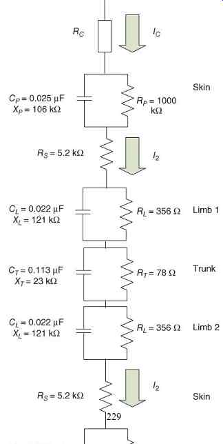
FIG 1 Circuit model of hand-to-foot conduction, with dry skin.
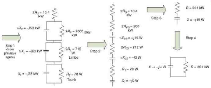
FIG 2 Circuit reduction of human body impedance with dry skin.
The total admittance of the element is calculated from the conductance and susceptance.
e.1
...where and The admittance is converted to impedance.
e.2
The impedance is broken out into two series elements.
e3
e.4
step 3. The series elements are summed.
e5
e.6
e.7
e.8
step 4. A parallel equivalent circuit is also created.
e.9
e.10
e11
This evaluation shows that the capacitive effect is minimal, as…
The model can be used to simulate the effects of electrical shock. With 120V AC applied, the current is…
This is what produces the "tingle" when house wiring is touched inadvertently.
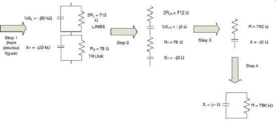
FIG 3 shows the circuit reduction of the example body with wet skin, assuming
that skin resistance is zero, making the only factor the internal body resistance.
With 120 V AC applied, the current is
Current at this level may cause ventricular fibrillation and possible death.
FIG 3 Circuit reduction of human body impedance with wet skin.
2. Frequency Response of the Human Body
Using the circuit model developed, the inductances may be added as elements in series with the resistances, and the effect of varying frequency can be found. Continuing the previous example, inductances had been found for the limbs and the trunk:
The resistances and capacitances were The equivalent circuit of a body part, including inductance, is shown in FIG 4.
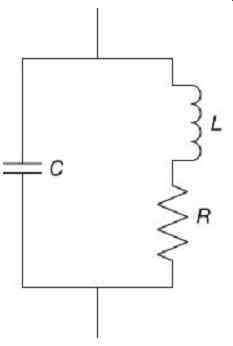
FIG 4 Equivalent circuit of a body part.
The impedance as a function of frequency can be calculated as e.12 [...]
For the trunk, , and , and resonance does not exist. For the limb, , and , and resonance does not exist. The maximum value of resistance for which resonance exists is...
e18
e.19.
For the trunk , for the limb.
These resistances are well below typical values for the human body. The impedance magnitude and angle plots are shown in Figures 5 and 6. For all frequencies in the kilohertz range, consisting of the power frequency and its harmonics, the resistance is the only circuit value which needs to be used. Considering the skin impedance, the skin consists of a resistance in parallel with a capacitance, along with a series resistance . The impedance can be calculated as e.20
In the example calculation, the resistances and capacitance were ...
The impedance magnitude and angle plots are shown in Figures 7 and 8. For all frequencies in the kilohertz range, consisting of the power frequency and its harmonics, the resistance is the only circuit value which needs to be used. There is a circuit pole at This is well below the normal power frequency.
The circuit model for the entire body, including resistance, capacitance, and inductance can then be constructed. Because resonance is involved, the series-parallel circuit reduction method used for the resistance elements will not correctly model the frequency response.
Therefore, the approach of summing the equivalent circuit models will be used.
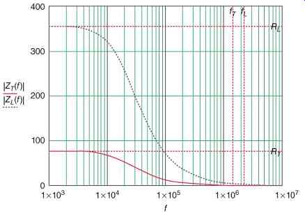
FIG 5 Impedance versus frequency plots for trunk and limb.
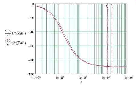
FIG 6 Phase angle versus frequency plots for trunk and limb.
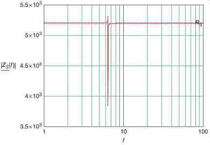
FIG 7 Impedance versus frequency plot for skin.
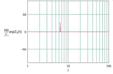
FIG 8 Phase angle versus frequency plot for skin.
[...]
e.21
The total body impedance for low frequencies is the sum of the resistances
e.22
The total body impedance for high frequencies is twice the skin resistance, as the resistances in parallel with capacitors are bypassed:
e.23
The internal body impedance for low frequencies is the sum of the resistances...
e.24
The internal body impedance for high frequencies is zero, as the resistances in parallel with capacitors are bypassed:
e.25
However, this is counteracted by the skin effect, which is not included in this model, so that at high frequencies, internal body impedances are not considered. The results are shown in Figures 9 and 10. As seen by the dip in the angle plot, there are system poles for the limbs at e.26
For the example being considered, …
There are system poles for the trunk at e.27 For the example being considered,
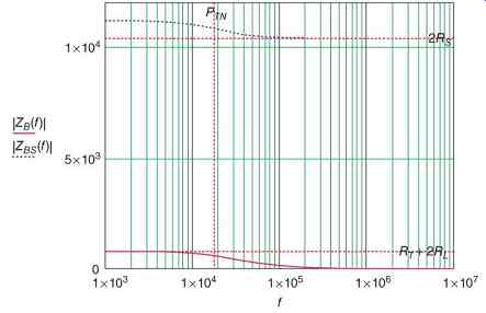
FIG 9 Total body impedance magnitude (ZBS) and internal body impedance (ZB)
versus frequency. PTN is the negative trunk pole at 18 kHz.
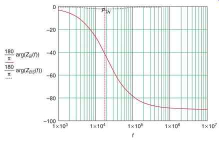
FIG 10 Total body impedance angle (ZBS) and internal body impedance (ZB)
versus frequency. PTN is the negative trunk pole at 18 kHz.