AMAZON multi-meters discounts AMAZON oscilloscope discounts
[Note: various equations denoted by "e." are not yet avail., but coming soon.]
1. Inductance in Electrical Theory
Inductance is a property where a conductor opposes a change in the amount of current flow, due to the magnetic field produced by the current flow. Since the human body is relatively small compared with the rate of change of power frequency currents, the inductance effect is relatively small. Nonetheless, it can have a significant effect at higher frequencies.
Inductance as a property of electrical systems, and specifically designed in a component such as an inductor, reactor, or transformer presents hazards to people who are working on the equipment or systems. The first hazard may be coming in contact with the energized conductors. Another important hazard is induced currents in conductive materials, which may cause electrical shocks, arcing, and heating. The effects of the magnetic fields produced by inductance can also affect human health, the most prominent example being biomedical devices such as pacemakers. For these and other hazards which may exist in particular circumstances, whenever an electrical equipment or system is designed, extreme care should be taken to prevent the inherent or designed inductances from causing safety hazards.
Definitions of inductance are a thorny matter, and inductance calculations can be extremely difficult. Inductance is defined as the ratio of flux linkages to current. Current is defined using Ampere's law and Maxwell's displacement current as eq.1 where eq.2 is the displacement field, and P is the polarization. The magnetic flux is eq.3.
Thus, eq.4.
The Ampère's law enclosure, also labeled L, is a circle enclosing one conductor of the parallel line. The external self- and mutual inductances are defined using S as a rectangle bounded by the two conductors. The internal self-inductance is defined by a rectangle bounded by the axis and surface of a conductor, FIG 1.
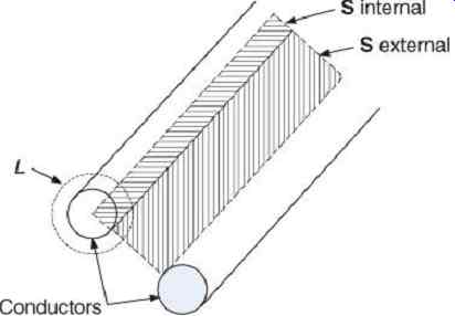
FIG 1 Surfaces of integration for internal and external inductance.
For a conductor pair of separation D and radius a, eq.5.
Alternatively, inductance can be calculated from magnetic energy. Inductive reactance is a measure of opposition to change in current. A tangential magnetic field H surrounds the axis of a conductor with a steady current I flowing.
This field is divided into two parts, internal and external to the conductor. In the two-conductor system, I is the same in both conductors, but with opposing directions, and two fields are produced, H1 and H2. Any change in the current in the conductor will result in a change in the magnitude of the magnetic field everywhere. The energy stored in the magnetic field is eq.6.
This will result in the familiar self and mutual inductances for a two-wire line.
eq.7
The portions of the magnetic fields that produce these inductances and that which produce the Poynting vector are not exactly the same. The field inside a perfect conductor produces inductance, but does not contribute to power flow.
For these concepts to have meaning, there must be a finite amount of magnetic energy. This will be the case in all practical applications. It is sometimes stated that a linear single conductor has infinite inductance, and that finite inductance is only introduced when return conductors are considered. This is contradictory to the usual practice of referring to a discrete component called an "inductor" or "reactor," which is not a complete circuit. It is also contradictory to the practice of calculating the inductance of transmission lines, which are also components and not circuits. In the microelectronics industry, Ruehli's concept of "partial inductance" is used.
When the inductance of a power transmission line is calculated, this is, in essence, a "partial inductance."
2. Inductance of Wires
The inductance of an open-wire line increases as the conductors are separated ( FIG 2).
Infinite separation, as in a one-wire line, would mean infinite inductance. In practice, the increase in inductance with spacing is very gradual. The inductance calculation (eq. 5) assumes, where is the conductor length.
This is because the lines of flux are assumed to be uniform and parallel in the area in the expression for flux (eq. 3). This may be a valid approximation for closely spaced conductors.
However, for widely spaced conductors, the assumption of infinite length is no longer reasonable.
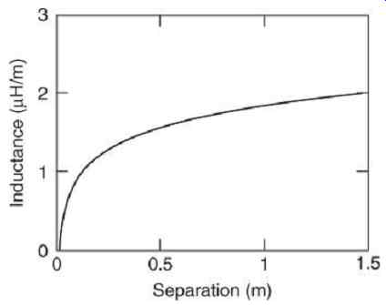
FIG 2 Inductance versus separation for an open-wire line.
Using the Grover formula (Grover, 1946) for the inductance of a straight conductor does not require a return conductor:
e.8
This is an example of partial inductance. In order to model the complete circuit, the partial inductance of each element must be included, as well as the mutual inductance between each pair of elements. The partial inductances of series elements cannot be added without considering these mutual inductances.
3. Example-Inductance of a Conductor […]
4. Example-Inductance of Trunk and Limb
Because the inductive reactance is several orders of magnitudes less than the resistance, it may be neglected in circuit analysis at power frequency. It is not necessary to refine the calculation for an elliptical as opposed to a circular cross section.
5. Inductors or Reactors
An inductor or reactor is a construction of conductors designed to contain an induced magnetic field for temporary energy storage.
The electric and magnetic fields over the inductor are parallel, resulting in no power transfer. Because power does not pass through an inductor, the Poynting vector follows the conductor through all its turns. When energy is stored in an inductor, the power flow is radial from the conductors into the magnetic field volume. The losses in an inductor, on the other hand, result from the same causes as those in a wire, and have a similar energy surface. FIG 3 shows examples of power reactors. The first is an outdoor current limiting reactor, with cast in concrete construction. Newer models use fiber glass epoxy construction. The second shows an indoor air core reactor with support by fiber glass sheeting.
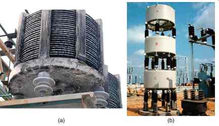
FIG 3 Power Reactors. (a) Cast in concrete reactor. (b) Modern fiberglass
epoxy outdoor air core reactors.
6. Skin Effect
The skin effect is not strictly a form of inductance, but a frequency effect on resistance.
This is why demonstrations with Tesla coils of a person touching an extremely high voltage source are possible. The extremely high frequency will cause a small amount of current to flow over the surface of a person's skin and not go deep enough to cause any physical harm.
Electrical current can only flow where a magnetic field is present within a material; in accordance with Ampère's law with Maxwell's displacement current correction, e.9 … where conduction current is dominant in conductors and displacement current is dominant in a dielectric. The electrical field is related to the magnetic field through Faraday's law:
e.10
When these equations are written for a wave along a plane surface, where B is directed along the x-axis and E along the y-axis, FIG 4, we have e.11.
These can be combined to form the equation for a wave which is normal to the surface of the conducting medium.
e.12 which reduces to e.13 and e.14 where…
? = complex propagation constant.
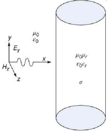
FIG 4 Electromagnetic wave entering a conducting medium.
The wave entering the conductor will be an exponentially decaying sinusoid, FIG 5, of the form e.15 where the real exponential term is the attenuation factor and the complex exponential term is the phase factor.
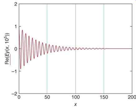
FIG 5 Magnitude of incident wave with ω
However, the propagation constant, ?, can be used to evaluate whether a material is a conductor, a dielectric, or a quasi-conductor at any given frequency. The ratio is the ratio of how much of the current is conductive over how much of the current is displacement current, FIG 6. The dividing lines are that indicates a conductor, while indicates a dielectric, while the region between indicates a quasi-conductor. Biological materials can be considered conductors at power frequencies, quasi-conductors at kilohertz frequencies, and dielectrics at milli-hertz frequencies and above.
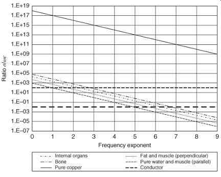
FIG 6 Ratio s/?? for biological materials, copper shown for comparison. Materials
are conductors above the "conductor" line, dielectrics below the "dielectric" line,
and quasi-conductors in between.
The distance where the magnitude of the wave decreases to 1/e is called the skin depth, d:
e16
FIG 7 shows the skin depth for biological materials, compared to a typical radius of 0.5 m, illustrating the fact that the skin effect is not biologically significant for frequencies of less than 0.1 mHz. This excludes commonly used power frequencies, which are less than 100 Hz.
The skin effect also changes the internal inductance of a solid conductor, because the .conduction occurs along the surface, making the inductance approach that of a tube rather than a cylinder. Exact calculation of skin effect resistance and inductance requires the use of the Bessel functions, which are necessary when any great precision is needed.
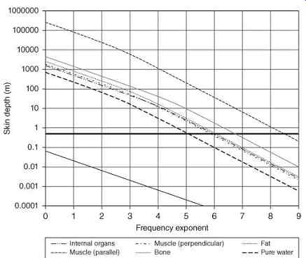
FIG 7 Skin depth for biological materials, compared to a radius of 0.5 m.
7. Cable Inductance
Cables comprise a large portion of electrical circuits, so the inductance of cables is a major factor in limiting hazardous short-circuit current. Also, the methods used in calculating cable inductance are important in electrical engineering and can also be utilized on other types of conductors. For shielded power cables, as in FIG 8, inductance is the sum of the internal inductance of the wire, the external inductance between the wire and the shield, and the internal inductance of the shield. For the capacitive ground currents being considered, the external inductance, , is calculated from the dimensions of the cable:
e.17
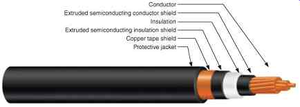
FIG 8 Single-conductor medium-voltage cable construction.
For normal phase currents, the distance between conductors would be substituted for the radius of the shield. The DC internal inductance of the wire for low frequencies is constant:
e.18
At higher frequencies, the internal inductance has characteristics similar to resistance, as shown in Figures 9 and 10, exhibiting a skin effect also.
e.19
The internal inductance is generally a small percentage of the external inductance, and is often ignored. The third inductance in the cable is that of the internal inductance of the shield.
Paul (2010) has given the calculation of this inductance by both the energy method and the method of flux linkages.
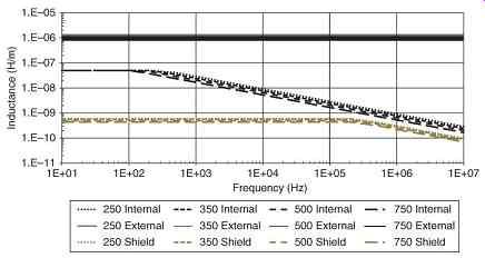
FIG 9 Internal and external inductance versus frequency for several common
cable sizes (kcmil).
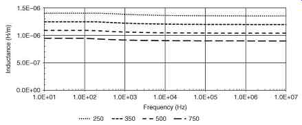
FIG 10 Total internal and external inductance versus frequency for several
common cable sizes (kcmil).
The shield transition frequency, , was calculated using (2.44) to be 263 kHz ( Table 1). For frequencies above , the effective thickness of the shield goes from to ...
===========
Table 1 Inductance of 5 mil (0.127 mm) Copper Shield
Size (AWG/kcmil) rs (m) rs + ts (m) fts (Hz) ldcs (H/m)
2 0.0105
0.0106
2.628E+05 8.056E-10
1 0.0110
0.0111
[...]
========
The internal DC inductance and the internal AC inductance of the shield above fts are approximated as e.20
e21
Below the transition frequency, where the skin depth is greater than the thickness of the shield, current distribution in the shield is uniform, and the DC shield inductance may be used. The shield inductance is plotted in FIG 9 and some of the factors used in the calculations are listed in Table 3. Because the internal inductances of the wire and shield are over an order of magnitude smaller than the external inductance of the wire, in equation (eq. 16), this can be used as a good approximation for the cable inductance.
e.22
8. Surge Impedance
Surge impedance is the equivalent resistance of a distributed circuit, where the inductance and capacitance are defined as per unit length, rather than as discrete quantities (Sutherland, 2012). The surge impedance will determine the ratio of voltage and current for a transient wave traveling down the line. When there is an abrupt change in surge impedance, there will be reflected and refracted waves, often resulting in severe overvoltage conditions. The surge impedance of a transmission system is defined as…
e.23
…where…
= inductance in H/m and
= capacitance in F/m.
Typical cable resistance, inductance, capacitance, and surge impedance at 20 kHz are shown in Table 2. Surge impedance versus frequency is fairly constant, FIG 11.
Table 2 Typical Cable Resistance, Inductance, Capacitance, and Surge Impedance at 20 kHz
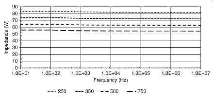
FIG 11 Surge impedance versus frequency for several common cable sizes (kcmil).
9. Bus Bar Impedance Calculations
The values of resistance are calculated or looked up in a reference (Copper Development Association, undated) using the area of the conductors and the resistivity of copper at 20°C, skin and proximity effects.
For example, with a resistivity of 1.72 × 10⁻⁸ O-m @ 20 °C, a 6? × ½? copper bar has a DC resistance of 8.89 × 10⁻⁶ O/m or 2.71 × 10⁻³ O/1000 ft @ 20 °C. This is divided by 2 if there are two parallel bars.
Correction for skin effect is shown in FIG 12 (Dwight, 1945, p. 225). the ratio , and at 60 Hz, By the figure in Dwight, . If two parallel ½? conductors are modeled as a single 1? conductor, then and .
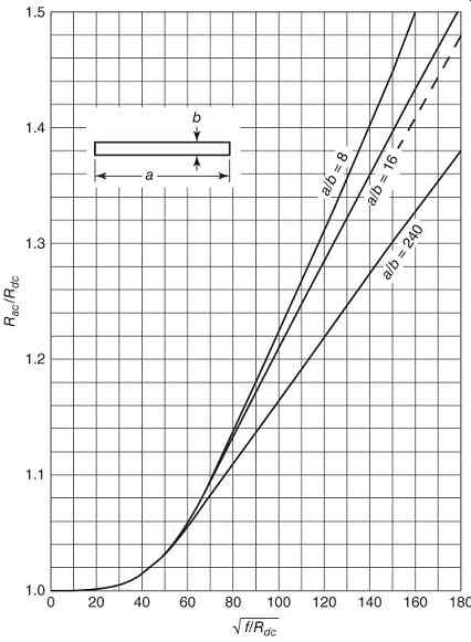
FIG 12 Skin effect in isolated rectangular conductors, Rdc in ohms per 1000
ft.
No formula or curve has been found in the literature for the proximity effect for rectangular bus bars. Dwight does have a curve for proximity effect for round wires, reproduced here in FIG 13. If we assume that the spacing is 90 mm or 3.54 in. and instead of the diameter, we use the thickness of 1.39? for two conductors, then the ratio and .
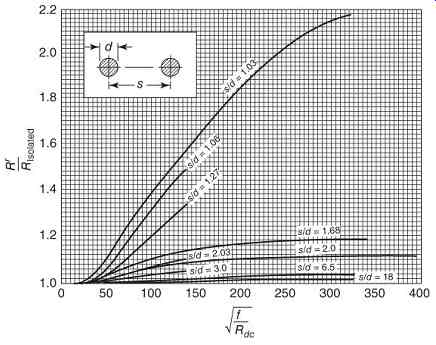
FIG 13 Proximity effect ratio in wires, Rdc in Ohms per 1000 ft.
The values of inductance are calculated as a three-phase inductance matrix, consisting of the self- and mutual inductances of the three-phase groups of bus bars.
e.24
This is next converted to a reactance matrix at 60 Hz.
e.25
The following expression for the geometric mean radius (GMR) of a rectangular bar with sides of lengths "a" and "b," may be used in these calculations:
e.26
The following more exact expression for the GMR of one rectangular bar with sides of lengths "a" and "b," may be used in calculating inductance:
e.27
The following expression for the geometric mean distance (GMD) between two rectangular bars with sides of lengths "a" and "b," and center-to-center spacing "s," may be used in calculating inductance:
e.28
The dimensions of the rectangular bus bar are shown in FIG 14.
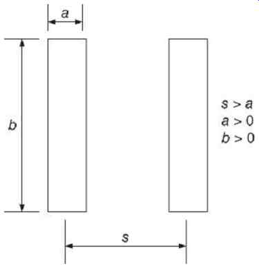
FIG 14 Dimensions of two parallel rectangular bus bars.
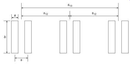
FIG 15 Dimensions of three-phase system with two parallel rectangular bus
bars per phase.
For example, two parallel bus bars per phase, with length and width dimensions of 6? × ½?, as shown in FIG 15, and similar to the bus bars in the photograph of FIG 16, excepting that the bus bars in the photograph do not have any spacing between the two bus bars in each phase, we consider a = 1.39 in. (0.0354 m) (pair of bus bars separated by 0.39 in. (0.01 m)) b = 6 in. = 0.1524 m s12 = 3.54 in. = 0.09 m (two adjacent pairs) s13 = 7.09 in. = 0.18 m (two outer pairs) GMR = 0.04197 m (pair of bus bars separated by 0.39 in (0.01 m)) GMD12 = 0.10557 m (two adjacent pairs) GMD13 = 0.18930 m (two outer phases)
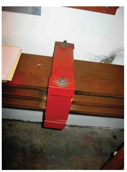
FIG 16 Three-phase system with two parallel rectangular bus bars per phase.
The resulting impedance matrix can be converted to a sequence impedance matrix, from which the positive and zero sequence impedances and are extracted to use in the calculations.
e.29
The results of applying equation (eq. 28) to the example system are shown in Table 3.
=========
Table 3 Sequence Impedances for the Example of Two Parallel 6? × 1/2?
Bus Bars Per Phase
Bus Bar Units Positive Sequence
Zero Sequence
=========