AMAZON multi-meters discounts AMAZON oscilloscope discounts
[Note: various equations denoted by "e." are not yet avail., but coming soon.]
1. Fundamentals of Capacitance
We are all familiar with the capacitance effect of the human body. The phenomenon of building up a static charge when walking on a carpet illustrates the charge-storing abilities of human body capacitance. Many electronic devices, such as touch-screen displays, touch-sensitive switches, and computer touch pads make use of this property. In terms of electrical hazards, the capacitance is a property which must be considered, along with inductance and resistance, in evaluating the effect of electrical currents on the human body. Capacitors also present a significant electrical safety hazard in their ability to store charge. Systems and equipment which use capacitors must be designed in such a way that this stored charge does not present a hazard to workers.
Capacitance is a property where an insulator opposes a change in the amount of electrical potential, due to the electric field produced by the potential. Since the human body is relatively small compared with the rate of change of power frequency potentials, the capacitance effect is relatively small.
Nonetheless, it can have a significant effect at higher frequencies. However, devices which have a large capacitance may be hazardous owing to the stored charge which they may contain.
Electrical energy is stored in the electric field, and in monopoles (electrons and ions) and dipoles (polarized molecules) within the material, all of which must be factored into the total relationship between voltage and current.
The dielectric losses may be considered as a bulk resistance and analyzed as previously discussed for resistors. For the initial discussion, the resistance will be assumed to be infinite, so that the capacitive effects may be isolated and analyzed separately. A real object, such as a body part, contains resistive, capacitive, and inductive components.
Capacitors as with resistors are not only a material property, but can be electronic components or power equipment. Capacitors are used in electronics for a wide variety of purposes. A few examples are shown in FIG 1. Capacitors may be used for blocking the flow of DC and only permitting the flow of AC; this application is called a coupling capacitor. A coupling capacitor might be applied in series with the input of an audio amplifier. Capacitors are widely used for filtering out AC components of DC voltages, where they are connected in shunt with the DC source. Bypass capacitors are small capacitors for filtering out high frequencies. Filter capacitors are large capacitors for smoothing out low frequencies, widely used in power supplies. Often, a large and a small capacitor may be applied in parallel. Capacitors are used in a wide variety of filter circuits, such as low pass, high pass, band-pass, and many more elaborate designs.
The uses of capacitors in electronics are virtually unlimited, and there are thousands of types available. Pictured here in FIG 1a is the ubiquitous ceramic disk capacitor, which generally has a low capacitance value, usually in the picofarad range, (this one has a capacitance of 47 pF) and can have a voltage rating from 100 V up to several kilovolts. Capacitors made of a roll of foil separated by an insulating material are used for higher capacitance values.
FIG 1b is a 0.1 µF, 600 VDC polyester film capacitor encapsulated in a hard resin case.
Earlier versions of this type of capacitor were made with paper insulation and dipped in wax for protection against moisture. When large capacitance values are needed, electrolytic capacitors are normally used as shown in Figure 2.1(e) and FIG 1c. These are polarized, and can carry a high capacitance value (10's to 1000's of µF) at voltages from low DC values to hundreds of volts, in a small package. Tantalum capacitors, FIG 1d, are widely used in computer circuits owing to their small size and low series inductance. They are available in both bypass and filter capacitor forms.
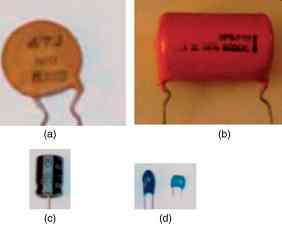
FIG. 1 Capacitors used in electronic applications. (a) Ceramic disk capacitor.
(b) Film capacitor. (c) Electrolytic capacitor. (d) Tantalum capacitors.
In terms of hazards to personnel, capacitors with a high capacitance value present the greatest danger due to stored charges. Even at low voltages, a discharge can produce a high current flow. Unless there is a parallel resistance to discharge the capacitor, the stored charge may last for a long time after the equipment is de-energized. Since the stored energy is as the voltage increases, the amount of capacitance which presents a danger decreases. Capacitors should always be discharged through a resistor, not by applying a short circuit, in order to avoid the dangers of arcing.
Capacitors used in electric power applications are typified by the rectangular cans with one or two bushings. The stack rack configuration FIG 2a is often used in substations. The stack rack configuration allows parallel and series combinations to be constructed, typically for application in substations. Capacitors may also be mounted on poles for applications along distribution lines, FIG 2b. Power capacitors are generally constructed of rolls of aluminum foil separated by polyethylene or similar plastic film, and then impregnated in oil. The rectangular cans at high voltage will contain just such rolled capacitors. At lower voltages, they may contain an array of smaller capacitors interconnected to make up the required value. Power capacitors are generally specified in kVAr and voltage, rather than in µF, although both values may be given.
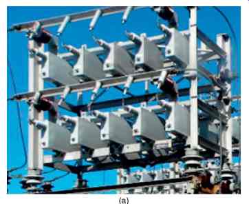
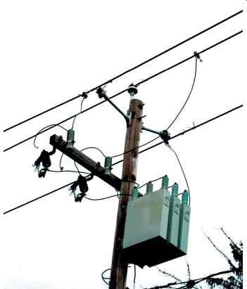
FIG 2 (a) Stack rack capacitors used in electric power systems. (b) Distribution
capacitor bank with switches.
These capacitors are typically used for power factor correction and harmonic filters. When capacitors are used on power distribution lines, they also provide the function of voltage support. Capacitor banks are often switched due to changes in load, power factor, or voltage.
Banks can be switched as a whole, or in steps.
Power capacitors are used in series with long, high voltage AC transmission lines to reduce the inductance effect. Smaller capacitors, called surge capacitors, are used to protect motors, generators, and transformers against high voltage transients. In power conversion systems, such as variable frequency drives (VFDs) for motor speed control, capacitors are used to store energy on an internal DC bus.
There are a variety of power electronic devices which provide continuous variation in capacitance at a faster speed than is possible with switching. These include the STATCOM or static compensator, the SVC or static VAR controller, the TCSR or thyristor-controlled shunt reactor which controls capacitance by varying a parallel reactor. Power capacitors are required to have internal discharge resistors (IEEE, 2002c), which discharge a capacitor of 600 V or less in no more than 1 min, and of greater than 600 V in no more than 5 min. The internal discharge resistor is not a substitute for discharging the capacitor through an external resistor before performing work on the bank.
2. Capacitance and Permittivity
The capacitance of the cylindrical geometry shown in FIG 3, is defined as…
eqn.1 where A = area of one of two identical conductive plates (m^2)
= distance between the surfaces of the two plates (m)
? = electrical permittivity of the material between the plates in farads/meter (F/m).
? = product of two components, ? = ?0?r.
They are:
?0 = permittivity of free space ˜ 10^-9/36p F/m
?r = relative permittivity of the material (unitless).
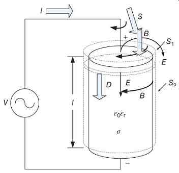
FIG 3 Capacitive energy storage.
The energy that is stored in a capacitor can be analyzed by drawing the Poynting surface, , around one of the end plates. The energy will enter one side of the plate, and exit the other side into the dielectric. Similarly, at the other plate, the energy will exit around the other conductor. Since the conductance, s, is zero, and the capacitor is lossless, the circuit model in FIG 4 is very simple.
eqn.2
If the surface is taken around the dielectric, …
eqn.3
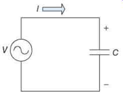
FIG 4 Circuit model of a lossless capacitive circuit.
In a pure capacitive volume, there is infinite resistivity, or zero conductivity, and thus no current flow. However, the electromagnetic energy must transition from one plate to another, so a vector quantity called the displacement current, D, is postulated:
eqn.4
The relative permittivity of some common materials is listed in Table 1, and of some common body parts in Table 2.
====
Table 1 Relative Permittivity (?r) of Some Common Materials (at Room Temperature) Material ?r
Copper 1.0
Vacuum 1.0
Teflon 2.1
Paraffin wax 2.2
Polyethylene 2.2
Plexiglas 3.4
Borosilicate glass 4.0
Ruby mica (muscovite) 5.4
Polyvinyl chloride 6.6
Pure water, sea water, fresh water 80
====
Table 2 Relative Permittivity (?r) of Some Body Parts (at Power Frequency)
Body Parts ?r
Skin (dry)-corneum 283
Bone >3800
Fat 1.5 × 10⁵
Muscle (perpendicular) 3.2 × 10⁵
Lung 4.5 × 10⁵
Liver 8.5 × 10⁵
Muscle (parallel) 1.1 × 106
====
The displacement current is the subject of one of the most famous equations in physics, Maxwell's displacement current correction of Ampère's law, which is the cornerstone of Maxwell's equations.
eqn.5
This demonstrates that while the conventional current flow produces a magnetic field, the change in displacement current also produces a magnetic field. It is changing displacement which causes energy flow through a capacitor. A capacitor is normally thought as providing energy storage in an electric field. This is true in the static case. In the dynamic case, it provides energy flow between two conducting materials, similar to a radio transmission. Each plate of the capacitor may be considered as an antenna.
When the dielectric materials contain polarized molecules (dipoles), the polarization may be caused by field cancellation from the capacitor plates. In addition, charged particles (ions) may be present within the material.
eqn.6
Thus the relative permittivity relates the polarizability to the electric field strength:
eqn.7 where
κ = electric susceptibility.
3. Capacitance in Electrical Circuits
Discrete capacitors are widely used in electrical and electronic circuits, and often present safety hazards in their own right. In a simple DC circuit, capacitors can be charged through a resistor (FIG 5) at an exponential rate. The circuit equations are
e.8
Solving the differential equation:
e.9
The result is the familiar capacitor charging exponential, as shown in FIG 6. Similarly, the discharge circuit is shown in FIG 7 and its curve is shown in FIG 8.
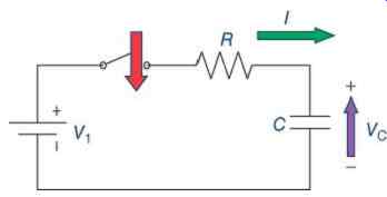
FIG 5 Capacitor charged from a DC source.
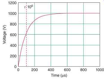
FIG 6 Voltage on 1.0 µF capacitor charged through a 100 Ohm resistor to 1 kV
with t = 100 ms.
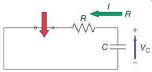
FIG 7 Discharge of capacitor charged from a DC source.
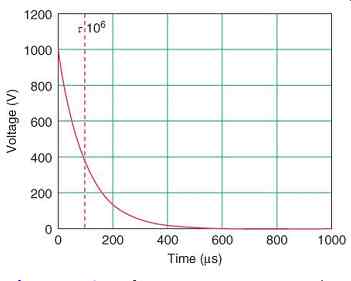
FIG 8 Voltage on 1.0 µF capacitor discharged from 1 kV through a 100 Ohm resistor
with t = 100 ms.
The equation for the discharge is calculated similarly as for the charging, and results in e.10 With an inductor in place of the resistor, the familiar series resonant circuit is constructed (FIG 9). The resonant frequency is e.11 while the voltage across the capacitor can be expressed as e.12…
...as shown in FIG 10.
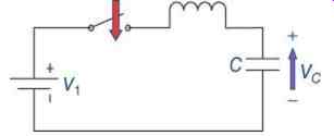
FIG 9 Oscillatory LC circuit.
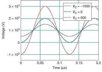
FIG 10 Voltage on 1.0 µF capacitor in oscillatory LC circuit with L = 20
mH and ?0 =
5.010 × 10⁻⁷.
The switching of capacitive loads, as in FIG 11, causes transient oscillations with high di/dt.
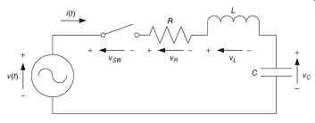
FIG 11 Series RLC circuit.
The voltage source is sinusoidal or e.13 where the peak voltage is:
e14
Using the definitions of the voltages across resistors, inductors, and capacitors, we have the classical differential equation for a series RLC circuit.
The inductor and capacitor are energy storage devices. The current through the inductor is zero with no voltage applied. Since the current in an inductor cannot change instantaneously, the current is zero both immediately before and after time t = 0.
e.15
The voltage across the capacitor is zero if it is discharged before the start of the switching operation. Since the voltage in a capacitor cannot change instantaneously, the voltage is zero both immediately before and after time.
e.16
Using the definitions of the voltages across resistors, inductors, and capacitors, we have the classical differential equation for a series RLC circuit:
e.17
This equation can be solved by a number of means, giving a generic solution of e.18 where e.19
e.20
The form of the solution is determined by the relation between and...
If , the system is described as being overdamped. The solution to the differential equation becomes: …
If , the system is described as being critically damped. The solution to the differential equation becomes: .
If , the system is described as being underdamped. The solution to the differential equation becomes or more conveniently, Supposing that the values of R, L, and C are then the resonant frequency is Then, because …. The system is underdamped. Initial voltages are and… At time , the loop equation becomes…
At time the underdamped solution equation is Since or else there would not be a solution, and , it follows that .
The derivative of the underdamped solution equation is:
Thus, A plot of the solution equation is shown in FIG 12.
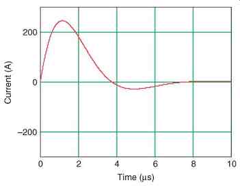
FIG 12 Oscillatory current transient in series RLC circuit with L = 12 µH,
C = 0.08 µF, and R = 14 Ohm.
4. Capacitance of Body Parts
Capacitance in the human body is primarily present between the layers of skin (0.02-0.06 µF/cm^2), and between the body as a whole and the earth.
4.1 Example-Skin Capacitance
Skin capacitance resides primarily in the dried layer of dead cells called the corneum, which is the normal surface layer. The thickness of the corneum is in the range 10-20 µm, and it typically consists of approximately 200 layers of cell membranes, which would each have a thickness of 0.05 µm. The capacitance of a single membrane is in the range of 2-5 µF/cm^2.
This allows the relative permittivity to be calculated:
Using the data from the skin with an electrode, the area , and depth , assuming.
This is in the accepted range of 0.02-0.06 µF/ cm^2. At 60 Hz, the capacitive reactance is The equivalent circuit of the skin can then be completed ( FIG 13). For AC current, the capacitance will dominate RP, resulting in lower skin impedance.
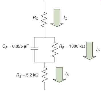
FIG 13 Example of skin impedance.
4.2 Example-Capacitance of Trunk and Limb
The trunk of the body from the previous example has a capacitance of At 60 Hz, the capacitive reactance is ...
The limb of the body from the previous example has a capacitance of flesh and bone. The capacitance of the bone is…
The capacitance of the flesh is The total capacitance of the limb is…
At 60 Hz, the capacitive reactance is…
5. Electrical Hazards of Capacitance
Power capacitors are used in electric power applications mainly for power factor correction and harmonic filters.
Filter capacitors for DC power supplies act to reduce the remaining AC components in a pulsating DC voltage after the rectification process is completed. These are usually large capacitors in the hundreds to thousands of microfarads, at voltages from the single digits up to the kilovolt range. Filter capacitors cause several electrical hazards. The first, and most obvious, is the risk of electrical shock from a capacitor charged to a high voltage with a high stored energy. A filter capacitor will charge to the peak value of the sinusoidal voltage being rectified. For example, if the power transformer for a piece of vacuum-tube electronic equipment has a 500 center-tapped secondary, such that , the full-wave rectified voltage will be However, the filter capacitor will charge to the peak value of voltage If the capacitor has a size of 100 µF, then the charge on the capacitor is The energy stored in the capacitor is This may provide a noticeable shock. The second hazard is of high discharge currents if such a capacitor is accidentally shorted, such as by an uninsulated screwdriver or other tool.
DC Link capacitors for AC motor drives act to store energy from the AC system after it has been rectified, in order that the inverter has a constant voltage source. These are usually large capacitors in the hundreds to thousands of microfarads, at voltages from the hundreds of volts up to the kilovolt range. DC Link capacitors can cause several electrical hazards.
The first, and most obvious, is the risk of electrical shock from a capacitor charged to a high voltage with a high stored energy. A filter capacitor will charge to the peak value of the sinusoidal voltage being rectified. For example, if the AC drive is powered by a 480 VAC system, and rectified by a three-phase bridge, the rectified voltage will be However, the filter capacitor will charge to the peak value of voltage If the capacitor has a size of 4500 µF, then the charge on the capacitor is The energy stored in the capacitor is This is more than sufficient to provide a fatal discharge if touched, and a severe arc flash if accidentally shorted.
6. Capacitance of Cables
The capacitance of a cable is a distributed quantity, and the longer the cable, the larger the capacitance (Sutherland, 2012). When cables are de-energized, they hold a charge for a long period of time unless properly discharged. It is important to know the capacitance of a cable and the voltage at which it was operated in establishing the proper safety precautions when working on it, even if de-energized.
Capacitance, , is calculated as e.21 where
= radius of the shield
= radius of the center conductor
?0 = 8.857 × 10⁻¹² F/m, and
?r = (unitless) is the relative permittivity (dielectric constant) of the insulation.
The dimensions and are shown in FIG 14. Values of for some typical cable-insulating materials are shown in Table 3 . More detailed simulations will also include the permittivity and conductivity of the semiconducting shields.

FIG 14 Shielded cable cross section showing radius of the wire and shield.
========
Table 3 Dielectric Constants of Some Cable Insulation Materials
Material | Description | Maximum Service; Dielectric Constant; Temperature (°C) PVC Polyvinyl chloride 105 3.4
XLPE Cross-linked polyethylene 90 5.0
MVXLPE Medium voltage cross-linked polyethylene 90 2.3
EPR Ethylene propylene rubber 90 2.5
========