AMAZON multi-meters discounts AMAZON oscilloscope discounts
[Note: various equations denoted by "e." are not yet avail., but coming soon.]
(cont. from part 1)
3. Resistance and Conductance
The fundamental definition of resistance (R) assumes that an object, such as the cylinder in FIG. 3, with a defined length and constant cross-sectional area (A) has a uniform material property which we call resistivity :
eqn.1
where R = resistance in ohms (O)
? = resistivity in ohm-meter (O-m)
= length in m A = cross-sectional area in m^2
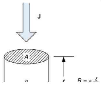
FIG. 3 Resistance, R, is derived from the resistivity, ?, of an object.
The reciprocal of resistance is conductance (G).
When applied to a uniform body such as the cylinder in FIG. 4, it is based on the material property of conductivity .
Conductivity is the reciprocal of resistivity.
eqn.2 where
G = 1/R = conductance in siemens (S) s = 1/? = conductivity in siemens/meter (S/ m)
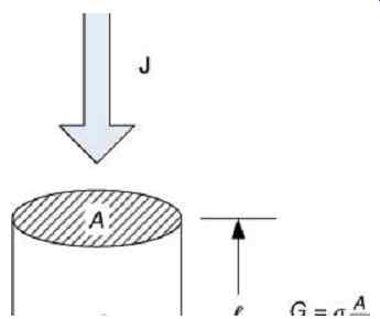
FIG. 4 Conductance, G, is derived from the conductivity, s, of an object.
When a voltage is applied to an object possessing the property of resistance, an electric current will flow through the object. In the case of metallic conductors, the current flow is accomplished by the motions of electrons, although other particles such as ions may be the means of current flow in other media, as we shall see later, such as when we consider the flow of current through the human body. It will be assumed for now that the diffusion of current throughout the object is uniform, although, in actuality, this is rarely the case.
Current flow in a wire (I) has been compared to the flow of water in a pipe , which is measured in cubic meters per second (m^3/s) or in cubic feet per second (ft^3/s). Volumes of electrons are measured in the amount of electrical charge possessed by the aggregate of electrons. A "volume" of electrons is not a fixed quantity of space, but a fixed number of charged particles. It is as if volumes of water were measured by a count of water molecules instead of the volume which they occupy (at a given temperature and pressure, of course). The unit of charge is the coulomb (C), which is the amount of electrical charge which is transported by 1.0 ampere (A) of current during a time period of 1.0 second (s). The charge on an electron (e) is . The number of electrons in a coulomb is 2.3.
There are electrons flowing in any given electrical conductor during every second when a current of 1.0 A is flowing.
Voltage is the electrical analog of pressure in a water pipe ( FIG. 5). The pressure (P) is measured in pascals (Pa) where a pascal is a pressure of one newton (N) per square meter (m^2). Thus,. In English units, pressure is measured in pounds per square inch (lb/in.^2). Since water can be pressurized without flowing, pressure is a form of potential energy. The amount of potential energy is the volume of water times the pressure. Energy is measured in joules (J), thus . When the water flows, the energy transferred is the pressure difference between the ends of the pipe times the internal volume of the pipe. Thus .... Thermal energy is dissipated by the flow of water under pressure in a pipe of a given diameter (d). The property of pipes to dissipate thermal energy due to the flow of water is called head loss. The head loss of a pipe is inversely proportional to the diameter of the pipe.
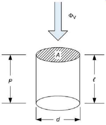
FIG. 5 Water pipe analogy.
Now consider an electrical system. Field strength is exerted on charges, which attempts to make the units of charge (such as electrons) move through a medium (such as a cylindrical object). Field strength is measured in volts, with one volt corresponding to a force of one newton-meter (N-m) per coulomb (C). Thus. Since electricity can be pressurized without flowing, volts are a form of potential energy. The amount of potential energy is the charge (coulombs) times the volts. Energy is measured in joules (J), thus . When the charge flows, the energy released is the voltage difference between the ends of the object times the charge in coulombs. The rate at which the work of charges flowing is performed is measured in watts (W) where. The thermal energy dissipated by the flow of one ampere under the pressure of one volt is one watt. The property of materials to dissipate thermal energy due to the flow of electric current is called resistance, which is measured in Ohms. The electrical conductivity of an object is analogous to the diameter of a water pipe. Thus one ohm of resistance with one ampere flowing through it will have a voltage drop of one volt and a thermal energy of one watt. If this continues for one second, one joule of energy will be used.
The linear relation of current to voltage in an object is the familiar Ohm's law. When one first considers a conductive object, such as a copper wire, we can see the simplest form of Ohm's law:
eqn.4
Typical conductivity values are shown in Tables 1 and 2. Considering resistivity as the inverse of conductivity,...
eqn.5 where...
J = current density in amperes/meter 2 (A/m^2)
E = electric field in volts/meter (V/m)
Table 1 Ohmic Conductivity of Some Common Materials (at Room Temperature)
Material s (S/m) Pure water 4.0 × 10^-6
Carbon 7.3 × 10^-4
Sea water 4.0
Lead 0.5 × 10^7
Tin 0.9 × 10^7
Zinc 1.7 × 10^7
Gold 4.2 × 10^7
Pure Copper 5.9 × 10^7
Silver 6.3 × 10^7
Aluminum 2.7 × 10^8
Table 2 Ohmic Conductivity of Some Body Parts (at Power Frequency)
Body Parts (S/m)
Bone 0.013
Fat 0.04
Liver 0.13
Muscle (perpendicular) 0.076
Lung 0.092
Blood 0.60
Muscle (parallel) 0.52
Sweat (0.3% saline) 1.4
Ohm's law for lumped circuit components, as shown in FIG. 6, is expressed in the form eqn.6.
...where I = current in amperes (A) V = voltage in volts (V) Using conductance instead of resistance, eqn.7
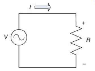
FIG. 6 Circuit model of a resistive circuit.
4. Example-Trunk of a Human Body
Given the trunk of a human body, represented by an elliptical shape as in FIG. 7, the area eqn.8 while the circumference may be found approximately using eqn.9
The exact calculation of the circumference of an ellipse requires the use of the elliptical integral, and is not necessary for this example. Given, for example, a person with a 1 m waist, then If the ratio a/b = 2, then:
and the area is A comparable circle with the same circumference will have showing the importance of using appropriate shapes in the model.
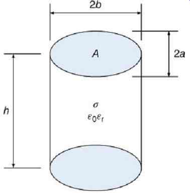
FIG. 7 Model of body trunk with elliptical cross section.
If the height of the trunk is 0.5 m, and the conductivity of internal organs is 0.1 S/m, then the resistance can be calculated as follows:
If the circular assumption had been used, we have which is 20% too small.
Example--Limb of a Human Body
Given a limb, FIG. 8, where , , , containing a bone with ...
The area of flesh is…
The resistance of flesh is based on the longitudinal conductivity of muscle, ...
The resistance of bone is based on the conductivity of bone, ...
The total resistance is... If a current of 1A flowed through the limb, 0.988A would flow through the flesh and 0.012A would flow through the bone. Total power dissipation would be 356W, with 351.4W in the flesh and 4.4W in the bone.
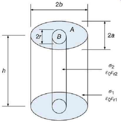
FIG. 8 Model of limb with elliptical cross section and circular bone at the
center.
6. Power and Energy Flow
For a uniform material, eqn.10
In electromagnetic field theory, power density is defined in terms of the Poynting vector:
eqn.11
...where S = power density in watts per square meter (W/m2) E = electric field vector in volts per meter (V/m) H = magnetic field intensity in amperes per meter (A/m) Over a closed surface S:
eqn.12
Consider the cylindrical body made of a material whose resistivity has a uniform value of ?, whose length is... , and whose radius , such that area . When an electric field is applied uniformly across each end of the cylinder, there is a constant axial voltage drop across the length . The magnetic field will consist of circular lines of force, such that the Poynting vector will be radial, pointed inward.
Energy which enters the volume, but does not leave, will produce heating. Energy which enters at one end of area A, will leave by the other end, contributing no net energy. Energy entering the sides of the cylinder contributes to heating. The surface area of the sides of the cylinder is the circumference times the length.
Assuming perfect conductivity and uniform current distribution, the electric field cannot sustain itself within the conductor, and is present only as radial lines leaving the surface of the conductor. The electric field strength, , of these radial vectors is...
eqn.13
…where is the line charge, is the permittivity, and the distance from the conductor center.
The radius of the conductor does not affect this result. In the case of electric power cables, a grounded electrostatic shield may encase each individual conductor, confining the electric field to within the cable insulation.
In a uniform cylindrical conductor, the magnetic field is divided into the part within the conductor, and that outside the conductor.
eqn.14
where…
eqn.15
B = magnetic flux density, tesla (T)
µ0 = permeability of free space = 4p × 10^-7 H/m
Assuming perfect conductivity and uniform current distribution, the electric field cannot sustain itself within the conductor, and is present only as radial lines leaving the surface of the conductor. The electric field strength, Er, of these radial vectors is eqn.16
...where ? is the line charge, ?0 is the permittivity, and r the distance from the conductor center.
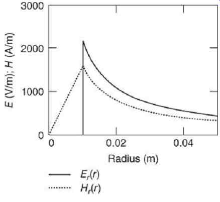
FIG. 9 Electric and magnetic fields around a circular conductor.
The radius of the conductor does not affect this result. In the case of electric power cables, a grounded electrostatic shield may encase each individual conductor, confining the electric field to within the cable insulation.
The magnetic field, Ht, on the contrary, is present both inside and outside a single conductor:
eqn.17 where...
a = radius of the conductor and I = current in the conductor.
The magnetic field vectors are tangential. The resultant vector direction of is thus away from the source and toward the load. If the electric flux lines, E, are radial and the magnetic flux lines, H, are concentric, the magnitude of the power density as a function of distance from the conductor center is the product shown in FIG. 10.
FIG. 10 Power density is highest closest to the conductors.
Most of the power transmission occurs within a relatively small radius of the conductors. The power density is substantially less in most of the space between the conductors. Here, 50% of the power is transmitted within the first 10% of the distance between the conductors. Power is transmitted in the same direction by both the outgoing and returning current flow.
If we take the closed surface S over the outside of the cylinder in FIG. 11.
eqn.18
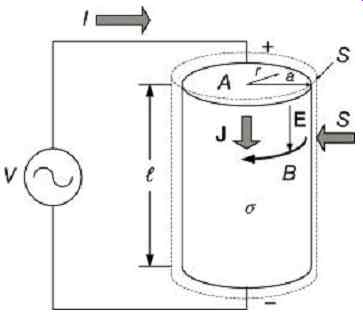
FIG. 11 Cylindrical conductor with applied voltage.
Ohm's law for electric fields is expressed as eqn.19 where J = current density in A/m^2 and = conductivity in siemens (S).
eqn.20 where ...
= resistivity in ohm-meters (O-m).
Multiplying by m^2, the expression is converted to circuit units, as in FIG. 11, resulting in the familiar Ohm's law, eqn.21 and the power equation, eqn.22.
Resistivity is thus a measure of the ability of a material to convert electromagnetic energy to thermal energy.
7. Sheet Resistivity
An object, such as skin, which consists of a sheet of material, can be modeled considering that the contact electrode current , divides into an area-proportional current and a spreading current , as shown in FIG. 12, with an equivalent circuit in FIG. 13. The depth current operates on the principle of sheet resistivity. Let RP be the resistance seen by the uniform vertical current over length , width w, and depth d:
eqn.23
Where and = number of squares. Typically, ns > 1.
Then eqn.24 so that eqn.25
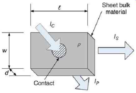
FIG. 12 Sheet resistivity.
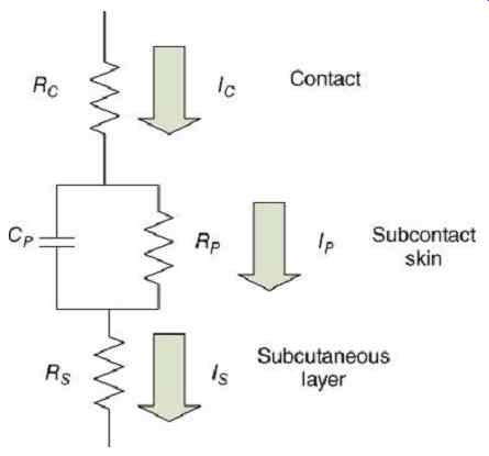
FIG. 13 Simplified equivalent circuit of skin.
8. Example--Square of Dry Skin
Consider a square of dry skin area 1 cm^2, with a resistivity of 1000 kO-cm^2 = 100 O-m^2. The resistance from an electrode also of area 1 cm^2
= 10-4 m^2 to the underlying body is
The thickness of the skin is in the range 10-100 µm. If the actual thickness is 50 µm, the resistivity of the skin may be calculated:
9. Spreading Resistance
Let be the resistance seen by the uniform horizontal current over length , width w, and depth d:
...eqn.26 expresses the resistivity on ohm-meters as in the formula for bulk resistivity. However, if we consider only the squares of surface area, then eqn.27 and eqn.28 where is the number of squares. Typically, ...
.At high frequencies, where the current only travels in the surface of the material, to a depth called the "skin depth" (by analogy to, but not the same as the biological skin).
10. Example--Circle of Dry Skin
In FIG. 14, the 1 cm^2 = 10^-4 m^2 circular contact area has a radius of ...
This is at the center of a circular area of skin with an area of 10 cm^2 = 10^-3 m^2, radius...
The ring of skin not covered by the contact has a width of (10.1 - 3.2) × 10^-3 m = 6.9 × 10^-3 m, and an area of 9 cm^2 = 0.9 × 10^-4 m^2.
Assuming for a skin layer of 50 µm.
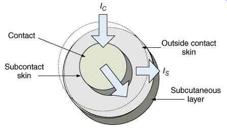
FIG. 14 Surface current flows.
The surface resistivity is eqn.29 while the subcutaneous layer composed of muscle and fat has a much lower resistivity.
Assuming for a subcutaneous layer of 2.0 mm:
The width of the exposed skin area is 6.89 × 10^-3 m. The circumference of the contact is 20 × 10-3 m. The circumference of the total skin area is 63.2 × 10^-3 m. The average value of the contact and the skin areas is 41.6 × 10^-3 m. The area of a square is thus approximately (41.6 × 10^-3) 2 m^2= 1.73 × 10⁻³ m^2. The number of squares is also approximately ns = 0.9/1.73 = 0.52.
Then…
The resulting skin model is shown in FIG. 15, with typical values in Table 3. The capacitance will be calculated in a later section.
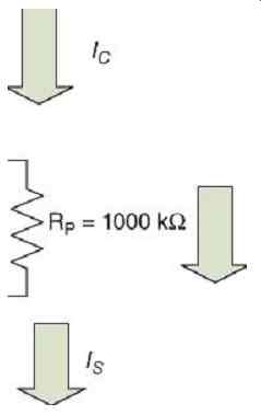
FIG. 15 Example of skin impedance.
Table 3 Surface Resistivity of Wet and Dry
Skin (at Power Frequency)
Body Part RP + RS (kO-cm^2)
Skin (dry) 100-1000
Skin (wet) <100
11. Particle Conductivity
The current we have discussed to this point is due to charges moving in response to the energy provided by the Poynting vector, directly as a result of energy flow in the circuit. There is a second type of current that must be considered, which is current as a result of the mechanical or chemical motion of charged particles. The electrochemical equilibrium of the human cell is disturbed by the flow of electrical current, and can have long-lasting effects. This is why every incident of electrical shock has a permanent effect, and medical attention should be sought. The field version of Ohm's law is then extended:
eqn.30 where
= diffusion coefficient in square meters per second (m^2/s)
= electric charge density in coulombs per cubic meter (C/m^3).
A charged particle, , has a voltage field around it, which decreases exponentially over a small volume, shown in FIG. 16. For a typical material at room temperature, this length, called the Debye length, ld, is approximately 10^-7 m. The voltage magnitude is eqn.31 Suppose that , then, ...
This field strength is in the order of millivolts, and the Debye length an order of magnitude greater than the thickness of a cellular membrane (10^-8 m). The movement of charges through a cellular membrane is shown in FIG. 17. The membrane has different equilibria on each side, which results in the potential difference shown in FIG. 18. The potential difference across a cellular membrane is defined by the Nernst equation, given here in simplified form for eqn.32 where
= Nernst potential
= ionic concentration outside the membrane in micromoles per cubic centimeter (µM/cm^3)
= ionic concentration inside the membrane, and
= ionic polarity.
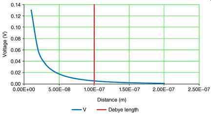
FIG. 16 Voltage around a charged particle and Debye length.
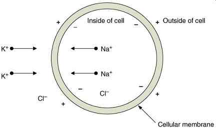
FIG. 17 Cellular membrane with ionic movements.
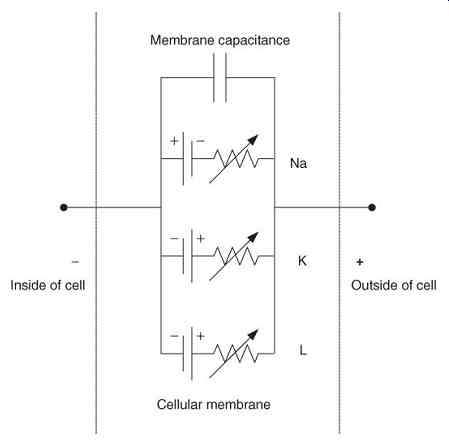
FIG. 18 Nernst potentials in cellular membrane.
The Nernst potential is given with different constants instead of 61 V in different sources, depending on the assumptions made, the choice of base for the logarithm, and the temperature.
It is given as 58 V at 17 °C with the logarithm to the base 10 or 25 V with a natural logarithm, also as 26 V at "room temperature" with a natural logarithm. The membrane voltage is in the range of ±100 mV. The potentials are associated with variable conductances, , which model the biological action of the cell membrane in allowing the transit of ions in one direction or another.
12. Examples--Potassium, Sodium, and Chlorine Ions
With the potassium ion K+, let...
With the sodium ion Na+, let ...
With the chlorine ion Cl -, let ...
When cells are exposed to external electrical fields, the ionic equilibria are disturbed, as the external fields move the ions across the cellular membrane in opposition to the normal cellular mechanisms. Even small electrical shocks can cause permanent injuries that are not always apparent initially.
13. Cable Resistance
Electrical cables play a major part of the electrical power system. The impedance of power cables is a major factor which limits the severity of short circuits and their related hazards. The resistance values for cables are the DC resistance of the conductor adjusted for skin effect at the frequency of the transients.
Resistance per unit length for a conductor with a circular cross section can be calculated in the ideal case as eqn.33 where
= DC resistance of the conductor in O/m A = cross-sectional area of the conductor in m^2
= radius of the conductor in m
= resistivity of copper at 20°C, and
= conductivity of copper at 20 °C.
The appropriate calculated or table value of DC resistance, , should be used for the particular cable in use, taking into account such factors as the type of copper, stranding, and coating.
Ambient temperature correction factors should be applied as necessary.
The skin depth is eqn.34 where
= skin depth in m
f = frequency, in Hz, and
= permeability of free space.
The skin depth of a conductor is inversely proportional to the square root of frequency.
For a copper conductor, eqn.35 as shown in FIG. 19 and Table 4.
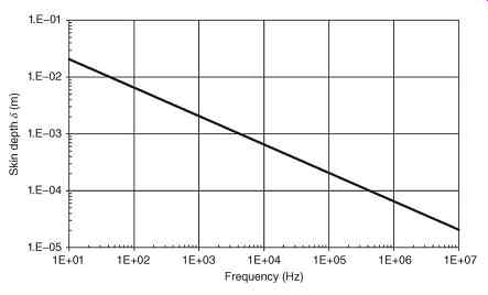
FIG. 19 Skin depth, d, of a copper conductor.
Table 4 Skin Depth, d, of a Copper Conductor
The frequency for a given skin depth is eqn.36 The exact formula for the ratio of conductor AC resistance to conductor DC resistance is a solution for the diffusion equation involving the use of Bessel functions. However, the following approximation may be made:
eqn.37
For the second case, where the skin effect is operative, the AC resistance is a function of the square root of the frequency. The factor can be used to calculate the AC resistance:
eqn.38
The breakpoint in equation (37) occurs when the radius of the conductor equals twice the skin depth:
eqn.39
A comparison of the radii of conductors and sheaths versus and is shown in FIG. 20.
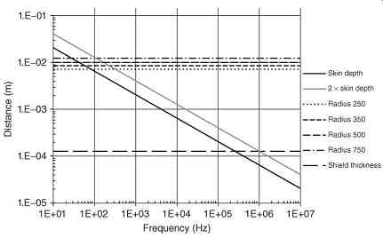
FIG. 20 Skin depth versus frequency and radii of conductors and shields for
several common cable sizes (kcmil).
Combining (eqn.34) and (eqn.39), the conductor may be said to be at the skin-depth transition frequency eqn.40 The skin-depth transition frequency for copper conductors with a circular cross section is eqn.41 Skin-depth transition frequencies, DC resistance, and the factor are shown in Table 5 for some common sizes of copper conductors.
Table 5 Resistance of Copper Conductors
This approximation is not used in calculating the power frequency resistance of conductors for power-system studies such as short-circuit and load-flow analysis. However, it can be used for transient studies above the transition frequency.
For high frequency transients, the frequency of interest may vary between 10 kHz and several megahertz, depending on the mode of the oscillation. Once the frequency of oscillation is determined, the resistance for the simulation may be calculated using (eqn.38).
At high frequencies, the cable acts as a coaxial cable and the return current flows through the shield. The currents being considered are capacitive ground currents through the cable and transformer capacitances and not the load currents which are phase to phase and do not involve ground. If the shield consists of a conducting tape of fixed thickness, its DC resistance may be calculated as follows:
eqn.42 where
= average radius of the shield in m and
= thickness of the shield in m
For higher frequencies, current flows only within the inner surface of the shield. The DC resistance equals the AC resistance for all frequencies below where the skin depth equals the thickness of the shield:
eqn.43
The skin-depth transition frequency for the shield is eqn.44
The skin-depth transition frequency for copper shield conductors is eqn.45
For a typical copper shield of 5 mils thickness or 0.127 mm, . When the transition to AC resistance is made, the resistance changes from being fixed by the thickness of the shield to varying with the skin depth by:
eqn.46
Then, eqn.47
The factor which can be used to calculate the AC resistance is shown in Table 6 for the shields of some common sizes of copper conductors.
Table 6 Resistance of 5 mil (0.127 mm)
Copper Shield
The shield resistances are plotted in FIG. 21, and are seen to be constant up to the shield skin-depth transition frequency. The conductor resistance goes to the load, and the shield resistance is the ground return, so that the total resistance is the sum of the two. The total resistance is plotted in FIG. 22 and is dominated by the shield resistance.
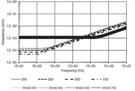
FIG. 21 Resistance versus frequency of conductors and shields for several
common cable sizes (kcmil).
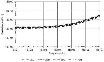
FIG. 22 Conductor plus shield resistance.