AMAZON multi-meters discounts AMAZON oscilloscope discounts
[Note: various equations denoted by "e." are not yet avail., but coming soon.]
1. Introduction
Electrical shock is caused by the passage of electrical current through the body. The amount of shock can vary from a small tingling sensation to severe burns, temporary paralysis, cardiac arrest, and death. Often, surprisingly small amounts of current can cause severe damage, depending where the current flows through the body. Electrical burns can be among the most severe because the current passes through the body and internal organs.
The amount of current that flows through the body is estimated in many sources as the ratio of the applied voltage to the resistance to current flow presented by the human body. This effect varies with the characteristics of the applied voltage in terms of duration, frequency of repetition, whether the voltage is alternating current or direct current, frequency of alternating current, rise and fall times of transient waves, and other factors. Similarly, the electrical resistance of the human body is not a single value, but has different values depending on the path of the current, the area of contact, the properties of skin and internal organs, the electrical characteristics of the voltage as described above, and of the corresponding current, the presence, condition, and characteristics of clothing, footwear, gloves, headgear and the like. Thus, for example, the IEEE Guide for Safety in Substation Grounding (IEEE, 2000), which is concerned with sinusoidal AC systems, despite an extensive discussion of the various factors affecting electrical shock, ends with an assumed body resistance of , and a duration factor of , where is the exposure duration. This section will examine the phenomenon of body resistance and its inverse, body conductance.
While such assumptions provide a starting point, the resistance of the human body is a complex, nonlinear phenomenon which deserves more accurate modeling, especially in cases where human life and health are at stake.
The second area where resistance affects electrical safety is in the resistance properties of the electrical circuits and components with which a person may come in contact with. In the case of shock hazards, circuit resistance in combination with body resistance will help to determine the magnitude and duration of the exposure to voltage and current. Electrical resistance is also a significant cause of electrical fires, of burns caused by coming in contact with an electrically heated object, and other possible injuries. When electrical systems and equipment are designed, these hazards of resistance itself, along with the potential hazards of coming in contact with energized resistors both in terms of electrical shock and thermal burns must be taken into account, so that it is inherently safe to work with and use the equipment.
2. Hazards Caused by Electrical Resistance
In electrical engineering, resistivity is a material property which affects the behavior of an electrical component. When the material takes a specific form, the resistance is determined from the resistivity of the material and its size and shape. Resistance is an example of what is called a "lumped circuit parameter," where a property of an extensive physical object is expressed as if it were a single object with a single property. For example, electrical conductors have an intrinsic degree of resistance, which could be considered as a form of opposition to their assigned task of being forced to carry electrical current. A copper wire contains resistance which, in the case of a small degree of current flow, will cause heating of the metal. This is due to the atomic structure not being entirely uniform, resulting in collisions between freely moving electrons and more stationary metal atoms. Heat is produced by the motion of atoms and molecules, so the copper wire will heat up as the current is increased. As the conductor becomes warmer, increased atomic motion results in more collisions between atoms and electrons, causing the resistance of the conductor to increase. This can be calculated using the "temperature coefficient of resistivity," for that material. While this quantity may sometimes be presented as a constant, it is actually a function of temperature also, and any particular value of which is given, in a reference table, for example, should be accompanied by a note at what temperature it was measured. In the vast majority of commonly used conductor materials, will increase with temperature. When resistance is the property which is desired, as in an electric heating device, the conductor is usually made of a higher resistivity material than copper, such as nichrome, iron, and steel. Resistance is also used in lighting, which began with Edison's carbon filament lamp, but is nowadays most recognized in the tungsten lamp.
At a certain point, the conductor's temperature will exceed the ambient temperature, and it may begin to feel warm or hot to the touch.
Now, one would not touch a bare copper wire which is electrically energized, but if the wire is sufficiently well insulated and the potential of the wire is low enough, one can touch the insulation. Considering devices using iron wire or similar materials, which are meant to produce heat, as in an electric toaster, stove, oven, space heater, or radiant floor, to name a few, one may feel the heat rising from the conductors. Undesired heat in a conductor may be caused by an overload, for example, connecting too many lamps to an extension cord or outlet, or by a short circuit, where two conductors come into contact. If the heat is sufficient to melt or burn through the insulation allowing an arc to form between the two conductors, then a fire can readily start. An internal short circuit which suddenly decreases the resistance of the device, resulting in a high current flow, may also cause overheating leading to a fire. Heating may also be caused by poor connections, because any junction between two conductors must encompass a certain surface area at a certain pressure in order to ensure good conductivity. A high resistance junction, such as a plug which is loose in a socket, may cause sufficient heating to start a fire. When wires and other conductors are being inspected as part of an electrical maintenance procedure, such as at a power plant, along a power line, or in a large commercial or industrial facility, infrared thermometers and infrared video cameras are often used to locate "hot spots" where the conductivity is poor and the conductors are heating up. This allows maintenance to be scheduled before a catastrophic failure such as an electrical fire can occur.
The detailed application of electrical cables and conductors is a subject in itself, requiring an analysis of both the heating effects of electrical current on conductors and insulation, and the thermal resistivity of the materials between the conductor and the ambient (such as air) which causes cooling of the conductor. In addition, the characteristics of protective devices, such as fuses and circuit breakers must be considered.
Tables for general use are provided in electrical code books, such as the National Electrical Code (NFPA, 2014) in the United States, and IEC 60364-5-52 (IEC, 2009a) in other countries. More detailed evaluation requires the use of mathematical modeling, such as the Neher-McGrath equations (Neher and McGrath, 1957) and the IEEE Power Cable Ampacity Tables (IEEE, 1994). Alternative calculation methods such as finite element analysis may also be used.
A National Fire Protection Association Report (Hall, 2012) estimates that of the 44,800 reported structural blazes involving homes, 12,000 had electrical causes. The electrically caused fires resulted in 320 deaths and over 1000 injuries (excluding firefighters and other emergency responders). While the vast majority of electrical fires were due to arcing short circuits, a significant number, perhaps one-third, were caused by heating of combustible materials by electrical sources. In many cases, the insulation of the wire or cable was ignited, perhaps by the overcurrent caused by a short circuit or by overloading of a circuit.
Electrical insulation for conductors, such as cables, cords, and the like, usually has a temperature rating. The circuit should be designed such that during normal loading, this temperature is never exceeded. Most fuses and circuit breakers have what is called an "overload characteristic," which is selected to operate at a lower temperature than the insulation of the conductors that it is protecting. Conventional "thermal-magnetic" circuit breakers are used in most homes. The current passes through a thermal element consisting of a bimetallic strip that bends as it is heated, causing the circuit breaker to open above a certain temperature. Thus the characteristics of the protective device work on a similar heating principle to the device being protected, and the protection is compatible with the protected device. At high short-circuit currents, faster action is required and the circuit breaker's magnetic element will quickly force the contacts apart. Thermal protection provided by fuses also works by heating of a wire, but in this case the wire will melt, causing the current to be interrupted. Fuses are normally designed with slow-acting regions for thermal protection and fast-action regions for short-circuit protection. These differences can be caused by changes in the width or thickness of the fusible element, or by holes punched in a fusible strip, or by making a fuse of two or more dissimilar materials.
Heating of conductors which are ductile also may cause them to stretch or lengthen, if they are suspended, as between two poles in a power line. A sagging power line may arc to some nearby person or object, resulting in electrical shock or an arc starting a fire in a combustible object such as a building or a tree. Even if protection systems cause fuses or circuit breakers to open, the damage may have already been done. A typical current-limiting fuse may operate in one-one hundredth of a second (10 ms), but a circuit breaker may take from two to five power cycles of the alternating current.
This amounts to 33-83 ms in a 60-cycle system or 40-100 ms in a 50-cycle system. This is more than enough time to kill a human being or to start a large fire. In many cases, power line conductors are uninsulated, and even in cases where they are insulated, a failure of some sort may cause the insulation to melt or break.
Safety regulations, such as the National Electrical Safety Code (IEEE, 2012a) require certain clearances, depending on the operating voltage between power lines and the ground and between power lines and other structures such as buildings. This clearance is not only affected by sag due to heating, but by motion due to the wind, and by loading from the accumulation of ice. Sag, of course, is affected by ambient temperature and by cooling due to wind, rain, and ice and snow accumulation.
Electric utility companies manage the flow of energy through power lines in accordance with many economic and operational factors, but they are always constrained by the load limits due to sag.
Resistors which are electrical components may be made of a volume or sheet of material, such as carbon, which does not conduct very well.
That will provide a convenient way to manufacture a specific value of resistance. The now obsolete carbon composition resistors, encased in a plastic shell, with a color code of painted bands indicating their resistance in ohms, and two axial leads, are the classic example of this type of resistor. This could be compared to a body part such as a finger or leg, which is a cylinder of poorly conducting material. The resistor has a number of properties besides resistance. The second most important is wattage, that is, how much power can be dissipated due to heating without damaging or destroying the resistor. The current-carrying capacity or current rating of the resistor will be directly related to the wattage. A resistor which is improperly applied or which experiences current flow which causes its rated wattage to be exceeded will heat, causing the encapsulating material to discolor, possibly to burn and eventually disintegrate.
Many electrical fires have been caused by overheating resistors. The resistor will also have a maximum voltage at which the resistor can carry a given current without overheating, above which the voltage drop across the resistor may become so high that arcing will occur across the surface of the resistor or through the air around it. Again, this can cause electrical fires, along with failure of the resistor.
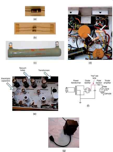
FIG. 1 Resistors used as electronic components. (a) Carbon composition resistor,
axial lead, ½ W, 470 W, 10% tolerance. (b) Carbon film, axial lead, 1/4 Watt,
10 kW, 5% tolerance. (c) Vitreous enamel-coated wire-wound power resistor,
1500 W. (d) Plate resistors in vacuum tube amplifier. (e) Vacuum tube amplifier
where plate resistors would be used. (f) Schematic of vacuum tube amplifier
where plate resistors would be used. (g) Isolation transformer (115 V, 250
VA) for servicing "transformerless" electronic equipment.
FIG. 1 illustrates some common types of fixed resistors used in electronic devices, ranging from computers and television sets to industrial equipment. The obsolete carbon composition resistor ( FIG. 1a), discussed above, is marked with a color code that is well-known in the industry, which gives its resistance value and tolerance. The wattage is indicated by the size of the resistor. Film resistors ( FIG. 1b) come in many varieties, carbon or metallic film, thick or thin film, being the most common. The carbon-film resistors shown come in the same general size and shape as the carbon composition resistors, with the same markings. The carbon film is coated on a ceramic tube, and then a spiral is etched away, leaving a helical track of carbon which creates the resistance needed, depending on its composition, length, width, and thickness.
Metal-film resistors are similar in construction, but use a metallic rather than a carbon-based film. Flameproof resistors are available, which eliminate the hazard of overheating mentioned above. When higher wattages are required, the wire-wound resistor ( FIG. 1c) is often used.
This consists of a ceramic cylinder wound with resistance wire (iron or nichrome, e.g.), inside a heat-resistant coating, vitreous enamel being a common choice. Here, color-coded bands are not used and the resistor data are simply printed on the enamel. If the ratings of the wire-wound resistor are exceeded, it may heat enough to cause nearby materials to burst into flame, but it will not burn itself. The enamel may blacken, the ceramic tube may crack, and the wire may burn through, resulting in device failure. The composition and film resistors are of the "axial lead" type, with the leads in line with the axis of the cylindrical form. The wire-wound resistor is shown with solder lugs for connections. These are extending radially from the surface of the cylinder. In other cases, a "radial lead" construction may be used, with the connection leads extending at right angles to the surface of the cylinder, and parallel to each other.
Components can be named by their location in a circuit as well as the type of construction. An example is the plate resistor used in vacuum tube (valve) circuits, as in FIG. 1d, is not to be confused with the plate resistors used in industrial systems, which are discussed below.
The plate resistor is usually a smaller carbon film or composition resistor, usually 0.5-1 W, used to limit the current in the plate circuit of a vacuum tube amplifier, FIG. 1e. This resistor also can pose a safety hazard for energized work, because it is at a voltage in the range of 100-1000 V and more in high power radio transmitters. The high voltage or "hot" lead is shown with dotted lines in FIG. 1f.
The hot circuit will go from the power transformer, shown in the photo of FIG. 1e and the schematic diagram of FIG. 1f, to a vacuum tube rectifier, electrolytic capacitors, and then to the plate circuits of the amplifier tubes, where the plate resistors are. The capacitors, with their stored charge, in fact, provide the greatest hazard in this circuit. Any repair shop which works on vacuum tube electronics, such as those contained in vintage equipment, amateur radio gear, or guitar amplifiers should observe the appropriate safety precautions for the voltage involved.
When "transformerless" circuits are used, with the tubes connected directly to the AC line voltage, the available fault current may be significant, and extra care is required, such as the use of an isolation transformer, FIG. 1g.
High power, high current resistors for industrial applications are shown in FIG. 2.
These resistors are used for a variety of applications including:
1. Neutral grounding resistors
2. Harmonic filter resistors
3. Snubber resistors
4. Braking resistors used in electric trolleys
5. Starting resistors for DC Motors
6. Load banks for testing generators.
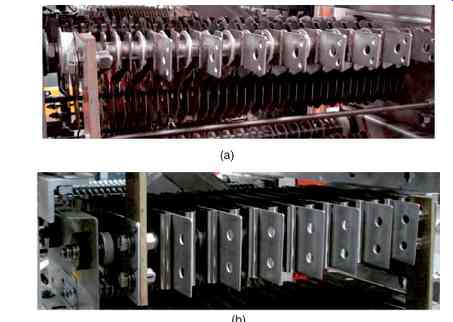
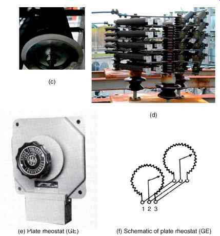
FIG. 2 Resistors used in electric power systems. (a) Plate resistor. (b)
Ribbon resistor. (c) Noninductive resistor. (d) Ribbon-wound resistor. (e)
Plate rheostat (GE). (f) Schematic of plate rheostat (GE).
The resistor in FIG. 2a is the plate resistor, consisting of flat sheets of steel which are spaced to allow for ventilation, and are supported on each side by spacer bars, with the metal section for each plate junction separated by insulating barriers from the adjacent plates.
The plates will thus have an arrangement similar to the schematic symbol for a resistor:
----/\/\/\/\/\/----
At each junction, a tab may be placed to provide a tapped resistance value.
The resistor in FIG. 2b is a ribbon resistor.
Here, a strip of steel is bent in the shape of a ribbon, similar to a piece of ribbon candy. It can also have taps made of tabs at the end of a bend. The resistor in FIG. 2c is a noninductive resistor. This is a film-type resistor on a ceramic tube, but unlike the standard carbon-film resistor, it does not have an etching in the form of a spiral. Such a spiral shape creates the form of a coil, and thus has significant inductance. The noninductive resistor has a resistive coating over the entire surface of the tube, except at the ends where contacts are made. The diameter is generally about 2 in. and length about 2 ft. The noninductive resistor will have the very low inductance characteristics which may be seen in a large diameter tubular conductor. The high power resistor shown in FIG. 2d is the ribbon-wound resistor, where a strip of steel is in the form of a ribbon with the flat surface parallel to the ends of the cylinder. This allows for good ventilation to occur between the turns.
In the figure, a group of ribbon-wound resistors are combined in series-parallel to provide a particular value of resistance, with the possibility of tap connections at the junctions.
One resistor in the group with taps attached to the ribbons can be used for fine-tuning.
The hazards associated with high power industrial resistors are primarily due to their open construction, which is necessary for cooling. The exposed conductors which make up the resistors can be not only a shock hazard but also a thermal burn hazard. The resistors must be mounted on insulators suitable for the working voltage and any harmonics or transients which may raise the voltage. Where there is the possibility of contact, such as when mounted on a concrete pad on the ground, or on top of a transformer, they should be enclosed in a grounded metal cage. There is little possibility of these resistors catching fire themselves, as no flammable materials are used in their construction or mounting. However, if flammable material such as some types of cable insulation is connected to them, this may present a possible hazard. Therefore, the connections to high power resistors are usually bare conductors.
Another type of power resistor is a variable resistor, in the form of the "plate rheostat" (where rheostat is another name for a variable resistor) pictured in FIG. 2e, with a representative schematic in FIG. 2f, named because of its shape like a dinner plate. Plate rheostats (General Electric Company, undated) are rated in the hundreds up to over a thousand watts, with plate sizes of 6-12 in. The rated currents are up to 26 A, and the resistance values vary from 20 to 5000 Ohm. Plate rheostats were used for:
• Speed control of dc motors.
• Use rheostat to control field excitation.
• Power-factor control of synchronous motors.
• Use rheostat to control field excitation.
• Voltage control of generators and exciters.
• Use rheostat to control field excitation.
• Adjustment of voltage in control circuits.
• Use rheostat to vary impressed voltage.
• Speed control of wound-rotor motors.
• Use rheostat to vary resistance in motor secondary; not over 15 HP.
They have largely been replaced by solid-state devices. Their application is described as A rheostat is a resistor provided with a ready means for varying its resistance. The usual application of rheostats is in the field circuits of motors or generators for the control of speed or voltage, or in control circuits. For most applications the size of the rheostat is determined by the characteristics of the load it must control.
Other applications require a certain number of steps which determine the rheostat size.
The principle safety hazards with plate rheostats are:
• exposure to high voltages at rheostat terminals;
• burns from coming in contact with heated plates.