AMAZON multi-meters discounts AMAZON oscilloscope discounts
[Note: "Tables" and various equations (denoted by "e.") are not yet avail., but coming soon.]
1. Introduction
The purpose of this section is to provide information on the effects on transmission lines of the increased fault currents which often accompany increased power flows. These effects can include conductor motion and the breakage of conductors and insulators, all of which can be hazardous to personnel. The proper design of transmission lines and equipment will include ensuring that high fault currents do not cause hazards to operating personnel, line workers, and passersby. The standard reference works on transmission lines, such as the EPRI "Red Book" (EPRI, 1975 1982, 2004c) and the Westinghouse Transmission and Distribution Book (Central Station Engineers, 1964), include very little data on short circuits and none on the effects of short circuit currents on transmission lines themselves. The exception to this is the Compact Line Design Reference Book (EPRI, 1978). To compile data for this section, technical papers and IEC standards relating to flexible conductor substation buses (covered elsewhere) have been referred to.
Some information has been found in an EPRI report on non-ceramic insulators (NCI) (EPRI, 1998). This section is adapted from EPRI (2006).
2. Effect of High Fault Current on Non-Ceramic Insulators (NCI)
Three main types of NCI are used on overhead transmission lines:
• Suspension insulators ( FIG. 1).
• Post insulators.
• Phase-to-phase insulators.
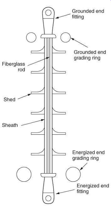
FIG. 1 Cross section of a typical transmission non-ceramic insulator (Source:
EPRI (2006)).
Each of the above may be applied in numerous ways:
• In general, suspension insulators are intended primarily to carry tension loads.
Suspension insulators can be applied in I-string, Vee-string, and dead-end applications.
• Post insulators are intended to be loaded in tension, bending, or compression. The most common application is horizontal posts.
These post insulators may be applied either alone or together with a suspension insulator in a braced post configuration.
Post insulators are also applied in substations as bus support or in disconnect switch applications.
• Phase-to-phase insulators are intended to be loaded in tension, torsion, bending, or compression. Phase-to-phase insulators couple two phases together in order to control conductor spacing during galloping.
This section deals mainly with suspension insulators although many areas may be relevant to both post and phase-to-phase insulators.
Modern suspension and strain insulators generally consist of the following main elements:
• Energized metallic end fitting.
• Energized end grading ring (need depends on application).
• Fiberglass-reinforced plastic rod (FRP).
• Polymeric weather shed system, consisting of weather sheds and sheath.
• Grounded end grading ring (need depends on application).
• Grounded metallic end fitting.
Grading rings, also called corona rings, are not installed at all voltage levels or on all applications, and often only a single grading ring is installed at the energized end. The method of construction and materials used depends on the manufacturer and application.
Concern has been raised over end-fitting damage caused by fault currents flowing during a flashover. Although tests have indicated that the critical tensile strength of an NCI may be reduced to 80% of its specified mechanical load (SML) rating during a power arc test, the insulator's tensile strength recovers to a level above its SML after the test. Since NCI are usually applied at less than 50% of their SML, this is not a significant concern. However, during a power arc, the galvanization of the end fitting may be damaged, making the fitting susceptible to corrosion. The long-term effects of localized heating on the end fitting, FRP rod, and weather shed system due to power arcs still require further research.
If a flashover occurred across the insulator because of a transient event such as lightning, the rubber weather-shed system or FRP rod may or may not have sustained damage. If the weather-shed system or FRP rod has been damaged (such damage is usually obvious), then the insulator should be removed (see FIG. 2). In some cases, the flashover may have caused no obvious damage to the insulator apart from areas of degalvanization of the end-fitting hardware. This may be especially true if the power arc terminated on the grading rings. Insulators whose external appearance indicates they have only sustained this type of damage are still of concern. Owing to the nature of grading ring attachments and end-fitting design, power fault currents usually flow through the end fitting, which is in direct contact with the FRP and rubber weather-shed system. Whether the increased end-fitting temperatures associated with the power arc current result in long-term degradation of either the polymeric rubber material or the FRP rod is unknown. Hence, it is advisable to remove such insulators from service.
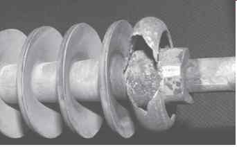
FIG. 2 Flashover damage sustained by an NCI (Source: EPRI (2006)).
3. Conductor Motion Due to Fault Currents
While normal transmission line construction, with widely separated phases, does not appear to be significantly impacted by conductor motion due to fault currents, it is an important consideration for compact transmission lines (EPRI, 1978).
Two parallel conductors, each carrying current, will be subject to a force of attraction or repulsion, depending on current direction. The magnitude of the force on each conductor is
eqn.1
where
I = current in each conductor
= length of each conductor, and
d = distance between conductors.
If the current flow in each conductor is in the same direction, the force will cause attraction; and, conversely, if the current is in opposite directions, the force will cause repulsion. For short-circuit currents, these forces may be sufficient to cause significant conductor movement, particularly where conductors are closely spaced (such as in Extra High Voltage (EHV) (EHV is generally considered to be 345 kV and above) conductor bundles or in adjacent phases of a compact line), because of the inverse relationship of conductor spacing and the resultant force. The actual movement of a conductor, considering inertia, is a function of both the magnitude of the current and the time it is applied, and is therefore dependent on circuit-breaker interrupting time.
A phase-to-phase fault will cause current in the two affected phases to flow in opposite directions. The two conductors will then be repelled and, on interruption of the fault current, will swing together.
If the current is due to a fault on the line section under consideration, the electrical consequences of conductor motion (even clashing) are generally unimportant as that section will be tripped out anyway. However, if the fault is on an adjacent line section, the motion may be serious as it might cause interruption of the unfaulted section.
"Through-fault" currents, or those supplied through a nonfaulted line to a fault elsewhere on the system, can be an important design consideration for compact circuits. Even though such currents on the compact line may be less than the maximum fault currents attainable on the system, they may be sufficient to be determining in the selection of phase-to-phase spacing or in establishing the need for insulating spacers.
The motion of conductors subjected to electromagnetic forces is similar to that of weighted, stretched strings, with the complication that the string is usually a compound conductor, such as an aluminum conductor, steel reinforced (ACSR). Relatively simple analyses of conductor motion of both vertically and horizontally spaced conductors can be shown to give results well within line design accuracy requirements.
4. Calculation of Fault Current Motion for Horizontally Spaced Conductors
FIG. 3 illustrates the conductor configuration used as a basis for calculations. It is assumed that the forces to which each catenary span of the conductor is subjected will cause the span to swing in a plane, as shown in FIG. 3(a). The plan projection of each catenary is again a catenary ( FIG. 3(b) and (c)). This assumption, supported by experimental results, simplifies the calculation technique. The most severe fault is phase to phase on adjacent phases, which impresses a cyclic separating electromagnetic force.
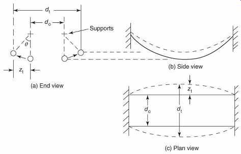
FIG. 3 Horizontal conductor motion during through-fault. (a) end view; (b)
side view; and (c) plan view (Source: EPRI (2006)).
Since all spans of a line contributing to a through-fault will behave similarly, the net pole-top force along the span, and therefore motion, will be zero. Consequently, each span can be assumed to be rigidly terminated.
5 Effect of Conductor Shape
The true shape of each conductor is a catenary, as shown in FIG. 4. For a catenary, 14.2
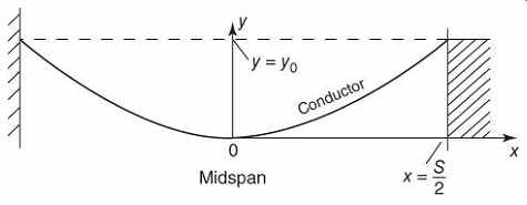
FIG. 4 Conductor geometry (Source: EPRI (2006)).
At , where is the span length (i.e., at the conductor support), let , where is the conductor sag, to define .
6. Conductor Equations of Motion
From the previous equations, the forces on a conductor are represented in FIG. 5, where...
= electromagnetic force of repulsion
= conductor weight
= actual conductor position at midspan when at rest
= actual conductor position at midspan, time
= effective position of mass and forces
= normal component of conductor tension.
FIG. 5 Forces on a conductor (Source: EPRI (2006)).
Resolving tangentially, the force accelerating conductor swing is
eqn.10
The conductor acceleration point is then
eqn.11
where is the gravitational constant.
Using a step-by-step analysis, the conductor velocity
7 Effect of Conductor Stretch
As the conductor deflects under load, the effective weight per unit length changes.
Resolving perpendicular to the conductor in the conductor plane, using the terminology of FIG. 5,
eqn.16
8. Calculation of Fault Current Motion for Vertically Spaced Conductors
As a conductor span moves upward owing to fault current forces, the tension is reduced and the acceleration is restrained by the increase in the effective conductor weight. Conversely, as a conductor moves downward owing to these forces, the acceleration is inhibited by an increase in conductor tension. Because of these effects, it is important that the modulus of elasticity be considered in calculations.
FIG. 6 illustrates a typical vertical conductor arrangement. As a simplifying approximation, it is assumed that the forces to which each conductor is subjected will cause an increase or reduction in sag, but that the conductor will retain a catenary shape. This assumption is supported by experimental results for low currents applied for long durations. The assumption is even more accurate for high fault current levels and short durations, where most of the kinetic energy is imparted to the conductor before the conductor can move appreciably.
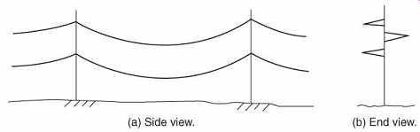
FIG. 6 Typical vertical conductor arrangement. (a) Side view and (b) end
view (Source: EPRI (2006)).
The terminology used in analyzing the vertical case is the same as for the horizontal case. The configuration used as a basis for calculations is illustrated in FIG. 7.
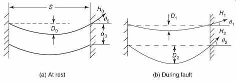
FIG. 7 Vertical displacement during fault.
(a) At rest and (b) during fault (Source: EPRI (2006)).
9. Calculation Procedure
From the rest position, , that is, all sags are equal. For any other position, assuming both conductors are a catenary, the average separation distance can be expressed:
FIG. 8 Conductor angle at support (Source: EPRI (2006)).
10. Calculation of Tension Change with Motion
If an initial conductor length and an initial conductor tension are assumed, then for any subsequent motion resulting in and , [...]
11. Calculation of Mechanical Loading on Phase-to-Phase Spacers
The electromagnetic forces during a phase-to-phase fault will act to move the conductors apart, placing phase-to-phase spacers in tension. After the fault is cleared, the conductors will swing together, compressing the spacers. These forces can be analyzed using the diagram of FIG. 9. Using the previously defined terminology, for any subspan swing angle, ,
This will be the maximum spacer force in both tension and compression for the usual case where the fault has cleared before maximum conductor deflection has occurred.
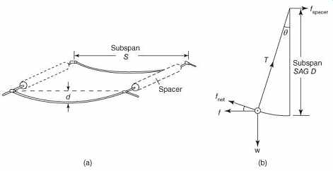
FIG. 9 Derivation of forces on spacers.
(a) general view of subspan and (b) midspan cross section of subspan (Source: EPRI (2006)).
12. Effect of Bundle Pinch on Conductors and Spacers
Transmission line spacers ( FIG. 10) are designed to withstand the compressive force on bundled conductors caused by short-circuit forces. Spacer compression may be calculated with the Manuzio formula (Lilien et al., 2000), originally for flexible bus substation design:
eqn.40
where
= compression force on the spacer in
= initial static tension on the conductor bundle in
= conductor spacing in mm
= conductor diameter in mm.
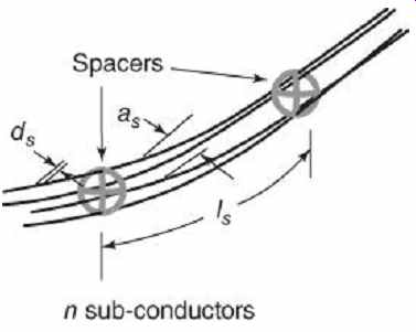
FIG. 10 Details of transmission line conductor bundle with spacers (Source:
EPRI (2006)).
Tests by Lillien et al. showed that the Manuzio formula underestimated the stress by 50%.
Better results (within ±10%) were obtained using finite element analysis. These results were extended to transmission line design. The Manuzio approach neglects
1. the pinch effect, which results in an increase in tension of the subconductors during the short circuit;
2. the asymmetry of the fault current;
3. the length of subspan between spacers.
All of these causes result in higher compression forces on spacers during faults. Lilien and Papaliou stress that the Manuzio formula should no longer be used, especially as fault current levels are increasing in transmission systems. After an extensive series of tests and computer simulations, they recommend a new calculation method based on the IEC 60865-1 approach (IEC, 1994 2011a) The subconductor ( FIG. 11) is assumed to take a parabolic shape between the spacer and the point where all the subconductors touch:
eqn.41
…where is the noncontact length, which must be calculated.
Simultaneous numerical solution of the following two equations is required:
= deviation from the horizontal (FIG. 11).
I = time-average short circuit current (CIGRE, 1996).
Solution of these equations results in values for , the compression force on the spacer and the length of subconductor before the pinch occurs. Finite element method simulations can also be used for this problem.
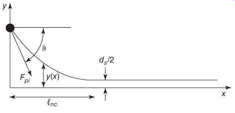
FIG. 11 Parabolic model of subconductor pinch forces (Source: EPRI (2006)).