AMAZON multi-meters discounts AMAZON oscilloscope discounts
[Note: "Tables" and various equations (denoted by "e.") are not yet avail., but coming soon.]
1. Introduction
Mechanical forces and thermal effects produced by high fault currents can damage or destroy substation equipment. This damage is a serious safety issue for a number of reasons. All substation equipment can suffer damage from mechanical forces caused by short circuits.
Examples include bending of bus work, sudden expansion of transformer coils, and breaking of insulators and bushings. In addition, even faults with rather moderate magnitude may cause long-term effects such as accelerated aging of dielectric insulation as a result of repetitive mechanical stresses. Solving the problem of increased fault currents means repeating portions of the original design process. Because substation design has become an automated procedure, the uprating should be in the nature of a design review. This section is adapted from EPRI (2006).
2. Definitions
Fixed bus bar end. The end of a rigid bus bar that is not free to rotate.
Pinned bus bar end. The end of a rigid bus bar that is free to rotate.
SCADA Systems. Supervisory controls and data acquisition systems.
Strain bus. A bus made of flexible conductors, which hangs from suspension insulators, such that
eqn.1
…where…
= distance between supports, in m
= length of bus conductor, in m
= length of one insulator chain, in m.
Slack bus. A bus made of flexible conductors, which hangs from post insulators, such that 13.2
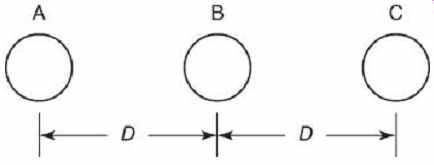
FIG. 1 Three-phase side-by-side bus bar configuration.
3. Short-Circuit Mechanical Forces on Rigid Bus Bars
3.1 Short-Circuit Mechanical Forces on Rigid Bus Bars-Circular Cross Section
The short-circuit forces on three, rigid, side-by-side busbars are shown in FIG. 1 and are calculated according to IEEE Standard 605 (IEEE, 2008):
eq.3
...where ...
= fault current force in N/m
= symmetrical rms fault current in A
= conductor center-to-center spacing in m
= a constant whose value is 1.00 for phase-phase faults on either conductor,
0.866 for three-phase faults on conductor B,
0.808 for three-phase faults on conductor A or C.
...is the decrement factor.
Where fault durations are less than 1 s or the ratio is greater than 5, the asymmetry of fault current waveforms produces additional heating, which must be taken into account:
eqn.4
...where ...
= fault duration in s
= time constant in s
= mounting structure flexibility factor.
This is 1.0 unless the heights of the mounting structures are greater than 3m (IEEE, 1998, Figure 4).
The short-circuit forces on a conductor are added to the other forces to produce a total force, which must be less than the minimum yield stress of the conductor material (Table 1) (IEEE, 2008, Section 11). The magnitude of the total force is 13.5.
The angle of the force below the horizontal is 13.6 where
= total vector force on the bus, in N/m
= wind force in N/m
= total bus unit weight, including ice loading and connectors, in N/m
= 1 if the bus conductors are vertical, otherwise 0
= 1 if the bus conductors are horizontal, otherwise 0
Table 1 Allowable Stress for Common Conductor Materials
The maximum allowable length between spans is limited by the maximum of the vertical deflection or the span length for fiber stress.
The vertical deflection is primarily an aesthetic concern, which is not affected by short-circuit forces. The maximum allowable length based on fiber stress is calculated from the maximum allowable stress in Table 1:
eqn.7 where
= maximum length of the bus in cm
= constant based on the number of spans and end types (Table 2)
= maximum yield stress in kPa2
= section modulus in cm3.
When increased forces are anticipated owing to increased short-circuit levels, supporting them with additional insulators can protect substation bus bars.
Table 2 Conductor Span Constant KS
3.2 Short-Circuit Mechanical Forces-Rectangular Cross Section
In the case of substations with rectangular cross-section bus bars, a proximity factor is used:
...eqn.8 where is taken from FIG. 2. is equal to 1.0 for a round conductor and is almost 1.0 for a square conductor. Conductor shape is most significant for thin, strip conductors.
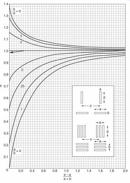
FIG. 2 Dwight curves for proximity factor (Dwight, 1945).
4. Dynamic Effects of Short Circuits
When excited by a displacement force, a rigid conductor will vibrate at its natural frequency, subject to damping forces (IEEE, 2008). The stimulus of a short circuit will provide a twice power frequency periodic force which may be amplified if the natural frequency of the bus bar is greater than or equal to the power frequency.
If additional supports are being added to stiffen the bus owing to increased fault currents, the dynamic effects should be checked as well. The natural frequency of the bus bar is 13.9 where
= natural frequency of the bus, in Hz
= pinning factor:
1.00 if both ends are pinned, 1.22 if one end is fixed and one end is pinned, 1.51 if both ends are fixed.
= modulus of elasticity (Table 3), in kPa
= moment of inertia of the crosssection, in
= mass per unit length, in kg/m.
If the resonant frequency calculation leads to the suspicion of a possible resonance problem, a dynamic or static finite element analysis should be performed.
Table 3 Modulus of Elasticity for Common Conductor Materials Material Modulus of Elasticity (kPa) Al alloy 6061-T6 Al alloy 6063-T6 6.895 × 10⁷ Al alloy 6101-T6 Cu 11.03× 10⁷ IEEE (2008).
In the case of hollow bus bars, internal weights or stiffeners may be added to dampen vibration modes.
5. Short-Circuit Thermal Effects
Heating of bus bars can cause annealing, thermal expansion or damage to attached equipment. The limit for thermal expansion adopted during the design of the substation is generally used. Annealing can occur at temperatures of 100°C or more.
The amount of current required to heat a conductor from the ambient to a given final temperature during the duration of a fault can be calculated:
eqn.10 where
= maximum allowable rms symmetrical fault current in A
= constant: 92.9 for aluminum conductors, 142 for copper conductors
= fault duration in s
= final conductor temperature in °C
= initial conductor temperature in °C
= constant: 15150 for aluminum, 24500 for copper
= International Annealed Copper Standard (IACS) conductivity as a percentage.
When the ends of a bus bar are not fixed, heating will result in thermal expansion, which may cause damage to attached equipment, such as switches, insulators, and other devices. The amount of expansion is 13.11 where
= initial bus bar length in m
= change in bus bar length in m
= coefficient of thermal expansion in 1/°C.
If both ends of the bus bar are fixed, then the resulting a force results may damage attached equipment:
eqn.12
…where…
= cross-sectional area in cm2 Where thermal expansion is anticipated owing to increased fault currents, expansion fittings can be added to long bus structures.
6. Flexible Conductor Buses
Flexible conductor buses may be constructed as strain buses, suspended from insulator strings (FIG. 3). This type of construction is usually used for substation main buses at high voltages . The slack bus construction (FIG. 4) with post insulators is normally used for connections between equipment within a substation. When high current-carrying capability is needed, conductors are often bundled (FIG. 5) separated from 8 to 60 cm with spacers at regular intervals of 2 to 30 m.
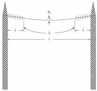
FIG. 3 Strain bus from suspension insulators (EPRI, 2006).
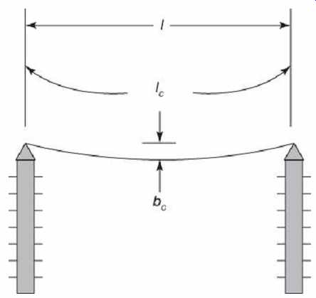
FIG. 4 Slack bus from post insulators (EPRI, 2006).
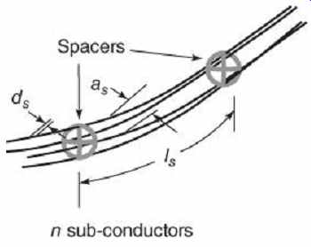
FIG. 5 Details of flexible conductor bundle with spacers.
The following are the effects of high fault currents on flexible conductor buses:
1. Increased tension on the conductors
2. Increased tension on insulators
3. Unwanted forces on support structures
4. Increased thermal stress on the conductors
5. Possibility of arcing due to decreased minimum clearance between conductors during swing
6. Possibility of damage due to increased drop force
7. Pinch-effect damage to conductors due to clashing, to spacers due to compression, and to suspension insulators and supports due to impulse tension.
Flexible conductor substation buses are discussed in detail in IEC Standard 60865 (IEC, 1994; IEC, 2011a) with further explanations in (CIGRE, 1996). The design standard is intended for horizontal buses up to 60 m long in a temperature range of -20 to +60°C and maximum sag of 8%. Automatic reclosing does not increase the effect of short circuits on flexible conductors. The simplified calculation procedure used in the standards has been verified by tests and detailed finite element method (FEM) simulations (Stein, Miri, and Meyer, 2000; Miri and Stein, 2002; Herrmann, Stein, and Keißling 1989).
6.1 Conductor Motion During a Fault
The short-circuit force on flexible conductors for a phase-to-phase or three-phase fault is approximately...
eqn.13
The forces will cause the conductors to separate (swing out), gravity will then bring them together (drop force), and they will oscillate with a characteristic period. The forces will also cause an elastic expansion of the conductor material, while the high currents will cause thermal expansion. If the bus is constructed from bundled conductors instead of single conductors, then the short circuit will force them together through the pinch effect, which produces tension on the conductor.
The IEC standard (IEC, 2011a) defines the ratio of electromagnetic force from the short circuit to the weight of the conductor:
eqn.14
...where ...
= number of sub-conductors
= mass of the sub-conductors in kg/m
= gravitational constant in m/s^2 then the direction of the resultant force is eqn.15
Without current flow, the static conductor sag is eqn.16 where
= is the static force on the conductors in N.
If the conductor oscillates at small swing-out angles, again, with no current flow, the period of oscillation is eqn.17
With a short circuit, the period is eqn.18
The maximum angle which the conductor can swing out for a given short-circuit current magnitude and fault duration can now be calculated. The swing-out angle at the end of the short circuit is eqn.19
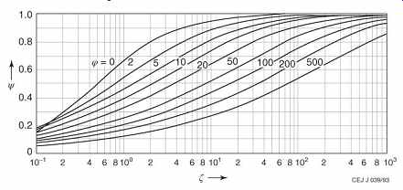
FIG. 6 Curves for determining the factor
? from IEC Standard 60865, Figure 7 (EPRI, 2006).
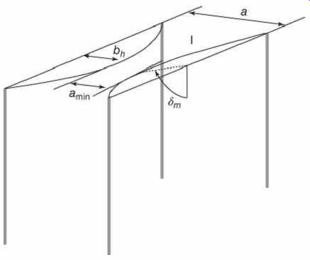
FIG. 7 Horizontal displacement and distance between midpoints of a slack
bus (EPRI, 2006).
Once the conductors have reached their maximum height, they will fall, experiencing the drop force:
eqn.37
6.2 Pinch Forces on Bundled Conductors
In bundled conductor configurations (FIG. 5), short-circuit forces cause the sub-conductors to come together rapidly. This discussion applies to sub-conductors arranged [...]
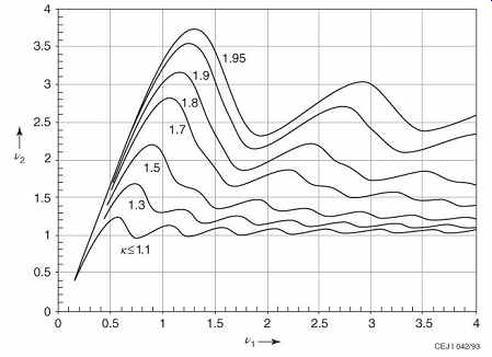
FIG. 8 Curves for determining the factors v1 and v2 from IEC Standard
60865, Figure 9 (EPRI, 2006).
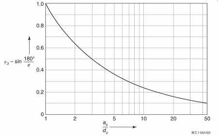
FIG. 9 Curves for determining the factor v3 from IEC Standard 60865,
Figure 10 (EPRI, 2006).
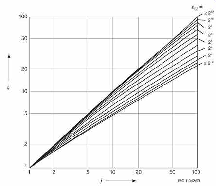
FIG. 10 Curves for determining the factor ? as a function of j and from
IEC Standard 60865, Figure 11 (EPRI, 2006).
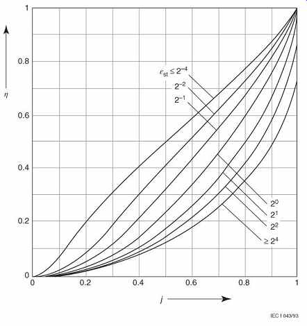
FIG. 11 Curves for determining the factor
? from IEC Standard 60865, when , Figure 12a (EPRI, 2006).
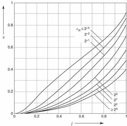
FIG. 12 Curves for determining the factor ? from IEC Standard 60865,
when , Figure 12b (EPRI, 2006).
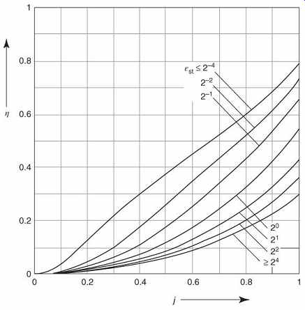
FIG. 13 Additional curves for determining the factor ? from IEC Standard
60865, when , Figure 11 (EPRI, 2006).
7. Force Safety Devices
When short-circuit forces increase, force safety devices (FSDs) can mitigate pinch-force effects.
A FSD (Miroshnik, 2003) is a deformable mechanical link which can be placed in series with a flexible substation bus to limit damage due to short-circuit forces. It is similar to a fuse, in that it is nonrecoverable, and must be replaced after a short circuit. The principle of operation (FIG. 14) is that of a metallic cramp, having two weakened cross-sectional areas which are calibrated for an actuation force of . The FSD is connected between the support structure and the suspension insulator (FIG. 15). When the total force exceeds , the FSD will be deformed, limiting the force. A graph of force limitation is plotted in FIG. 16.
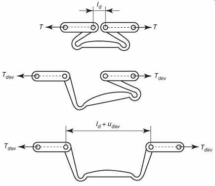
FIG. 14 Operation of force safety device (EPRI, 2006).
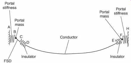
FIG. 15 Connection of FSD to flexible substation bus structure (EPRI,
2006).
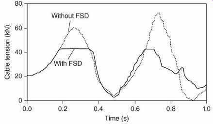
FIG. 16 Limitation of bus tension by FSD (EPRI, 2006).
8. Substation Cable and Conductor Systems
There are many types of cables and conductors used in substations (IEEE, 2007c). These include the following:
1. High-voltage power cables, defined as >1000 V. These may connect to other substations, to substation equipment, or to customer loads.
2. Low-voltage power cables, defined as >1000 V. These supply auxiliary power to substation equipment.
3. Control cables. These include instrument transformer secondary cables.
4. Instrumentation cables. These are used primarily for SCADA systems.
5. Overhead secondary conductors. In distribution substations, these medium voltage open-wire lines are the termination points of distribution feeders.
8.1 Cable Thermal Limits
Cables are subject to thermal damage from prolonged exposure to short-circuit currents.
Protective relay operating times and circuit-breaker clearing times must be fast enough to prevent prolonged overheating (IEEE, 1993, Section 5.6.2). Although the protection requirements of the National Electrical Code (NEC) (NFPA, 2014) do not apply in most substations, they should be considered when evaluating cable protection systems.
In addition to the NEC requirements, it is recommended that cable protection adhere to the limits of the cable damage curve for the insulation type as published by the cable manufacturers.
eqn.52 where ...
= symmetrical short-circuit current in A
= conductor cross-section in circular mils
= initial conductor temperature in °C, the maximum continuous conductor temperature for the insulation system is used, typically 75 or 90°C for low-voltage cables.
= final conductor temperature in °C, the short-circuit temperature limit of the insulation system is used, typically 250°C for low-voltage cables.
= heating temperature constant for the conductor material, 234°C for Cu and 228°C for Al.
Similar limits are available for the sheaths of medium-voltage cables. They should be used for ground fault currents. In the case of increased fault current levels, protective relay settings should be changed, as necessary, to protect the cables. If this is not possible, resizing of the cable may be necessary.
8.2 Cable Mechanical Limits
When a short duration fault bends a cable, the mechanical effect is more significant than the thermal effect. Permanent deformation may occur in plastic-insulated single-core cables. When cleats confine a cable such that short-circuit forces create outward bows with small bending radii, the cable may be damaged. Friction between the cleats and the cable may damage the outer sheath. Softening of the insulation by simultaneous heating further increases the damage caused by bending of the conductors. Proper support of cables can prevent this type of damage from occurring.
9. Distribution Line Conductor Motion
When overhead distribution lines enter substations, the opportunity exists for the substation to be exposed to damage from distribution faults (Ward, 2003). A fault on the distribution line causes the overhead conductors to swing side-to-side closer to the substation. As a result, the conductors may move close enough to arc (0.1 m) or even touch.
This causes a second fault, which may cause increased stress on the substation transformer and cause backup protective devices to operate.
Ward prepared a computer program that calculates critical clearing-time curves for overhead distribution conductors, based on conductor motion. Critical clearing time increases as spans decrease. The following are possible solutions to the problem of damage caused by distribution conductor motion:
Using faster recloser time curves. This is the preferred solution, if it is possible.
Installing fiberglass spacers at mid span to shorten the effective span. This is fairly inexpensive.
Adding intermediate poles to shorten spans.
This is expensive.
Increasing the phase spacing. This requires replacing cross arms, and is expensive.
Removing slack in the lines to reduce conductor motion. This is time consuming and expensive.
The first two options, faster reclosing times and fiberglass spacers at mid span, are the best alternatives if increased levels of fault current result in added stress to the substation due to overhead distribution line faults.
10. Effects of High Fault Currents on Substation Insulators
Brittle fracture of non-ceramic insulators (NCIs) have mostly occurred in polymer suspension insulators, however, the same problems could occur in post-type insulators. In terms of short-circuit stresses, exceeding the mechanical loading limits could result in cracks or splits in the rod or in damaged seals. Water intrusion leads to brittle fracture, through the leaching of acids in combination with tensile stress.
10.1 Station Post Insulators for Rigid Bus Bars
High fault current forces on rigid bus bars are transmitted to supporting insulators, which will be subject to forces that may exceed their design limits. The effects on the insulators could be cracks, fractures, or breakage. These, in turn, will weaken the support structure of the bus, resulting in greater damage should a second fault occur before the damage is repaired. The action of reclosers is of particular concern here.
The short-circuit force on a bus bar is transmitted to the insulator (IEEE, 2008, Section 12) through the bus-support fitting (Figures 17 and 18):
eqn.53
...where ...
= bus short-circuit force transmitted to the bus support fitting in N
= effective length of the bus span in m.
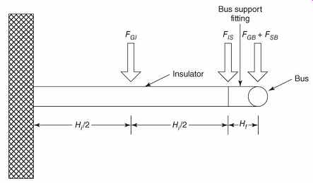
FIG. 17 Insulator configuration for vertical bus (EPRI, 2006).
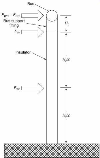
FIG. 18 Insulator configuration for horizontal bus (EPRI, 2006).
Similarly, the gravitational forces are
...where...
= gravitational force transmitted to the bus support fitting in N
= weight of the bus in N.
The cantilever force on the insulator is then 13.54 where
= overload factor for wind forces, typically 2.5
= overload factor for fault current forces;
this should also be 2.5, unless certain resonance criteria are met.
= overload factor for gravitational forces, typically 2.5
= wind force on the insulator in N
= height of the insulator in cm
= height of the bus centerline above the insulator in cm.
If the cantilever force is exceeded as prospective fault currents increase, two possible solutions are (i) to increase the number of insulators, thus decreasing or (ii) to replace the insulators with units having greater cantilever strength. If insulator spacing is changed, the mechanical resonant frequencies will have to be recalculated, and a dynamic study may need to be performed. Experimental results (Barrett et al., 2003) show that the IEEE method is conservative, and it is unlikely that increased fault currents will damage an IEEE-designed insulator structure.
10.2 Suspension Insulators for Flexible Conductor Buses
In accordance with (IEC, 2011a), the forces calculated shall be used with multipliers according to the type of insulator, as shown in Table 4.
Table 4 Insulator Force Multipliers
Force Post Insulator
Chain Insulator
Tension 1.5 1.0
Drop 1.0 1.0
Pinch 1.0 1.0
11. Effects of High Fault Currents on Gas-Insulated Substations (GIS)
Gas-insulated substations (GIS) are designed and tested in accordance to (IEEE, 2011), and have short-circuit ratings as listed in Table 5.
These are for external faults, where the GIS is tested in the same manner as circuit breakers.
The internal arcing fault-withstand capability of GIS is based on the thickness of the metal walls and the gas pressure (IEEE, 2011), and is thus not easy to upgrade. The withstand times are listed in Table 6. IEC standards are similar in regard to short-circuit ratings as well as burn-through times. The time to puncture an aluminum plate is approximately (Boeck and Krüger, 1992) 13.55 where
= time in ms
= constant
= thickness of the aluminum in mm
= current in kA.
Table 5 GIS Short-Circuit Ratings Short-Time Current-Carrying Capability (kA, rms) for a Specified Time of 1 or 3 s
Table 6 GIS Phase-to-Ground Burn-Through Times
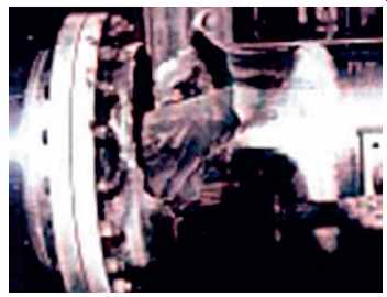
FIG. 19 GIS enclosure punctured by a rotating arc (EPRI, 2006).
A rotating arc can puncture a GIS wall in two different ways (Boeck, 2003). If there is an oblique arc, which rotates, the burst will be similar to that shown in FIG. 19. If an insulating barrier stops the moving arc, the vertical arc will puncture a hole in a much shorter time. The internal design of GIS is intended to keep the arcs moving and to prevent them from sweeping over the same locations more than once.
A statistical analysis (Trinh, 1992) shows that: "An increase in the mean fault current from 20 to 30 kA raises the risk of burn-through from 0.34 to 0.78, which illustrates the importance of designing the GIS in terms of the distribution of the local fault current." This is expressed as a probability formula:
eqn.56 where ...
= risk of burn-through of a GIS having an envelope thickness associated with a fault at a certain location on the transmission system
= probability density of the local fault current ic
= probability that the burn-through time will not exceed tc
= probability density of the fault-clearing times.
When a GIS unit is inspected and maintained, or replaced after a fault, very specific safety procedures should be followed (IEEE, 2011).
Sulfur hexafluoride is nontoxic, but produces numerous toxic by-products during arcing and burning.