AMAZON multi-meters discounts AMAZON oscilloscope discounts
[Note: "Tables" and various equations (denoted by "e.") are not yet avail., but coming soon.]
(cont. from part 2)
11.5 Testing of Low-Voltage AC Power Circuit Breakers
According to ANSI Standard C37.50-1989
For AC LVPCBs covered in ANSI C37.50-1989 (ANSI, 1989), the tests include the following:
1. Overload switching tests verify the circuit breaker can withstand repeated overloads at 600% of the rated currents.
2. Endurance tests verify that the circuit breaker can withstand multiple switching operations at 100% of the rated current.
3. Short-circuit current tests verify that the circuit breaker can safely interrupt its rated short-circuit current in the case of a short circuit.
Each type of test is conducted in specific test circuits according to the voltage and current ratings, number of poles (individual breaker units within the overall case), and circuit type (single-phase and three-phase). Each test also has a specific sequence of operations for repeated closings of the circuit breaker being tested.
ANSI C37.50 tests of AC LVPCBs are designed for breakers rated 60 Hz, with the test frequency being in the range of 60 Hz ± 20%.
AC circuit breakers have standard frame sizes (maximum ampere ratings or continuous-current-carrying capability) listed in TABLE 24 as specified in IEEE Standard C37.16-2009 (IEEE, 2009b). The standard fuse sizes are listed in TABLE 25. The nominal and maximum AC voltage ratings for LVPCBs are listed in TABLE 26. The interrupting ratings of the circuit breakers, defined as "the highest RMS symmetrical current at the rated voltage that a device is intended to interrupt under standard test conditions" are many times larger than their ampere ratings. For unfused AC LVPCBs rated under ANSI C37.16-2009, the interrupting ratings range from 22 to 200 kA.
Fused AC LVPCBs have a 200 kA interrupting rating.
TABLE 24 Standard Frame Sizes for AC and DC LVPCBs
Frame Size (A)
- 600
- 800
- 1600
- 2000
- 3000
- 3200
- 4000
- 5000
- 6000
Source: IEEE (2009a).
TABLE 25 Standard Fuse Sizes for AC LVPCBs
TABLE 26 Applicable Voltage Ratings for AC LVPCBs Maximum AC Voltage (V) | Nominal AC Voltage (V)
- 254 | 240
- 508 | 480
- 635 | 600
Source: ANSI (1989) and IEEE (2009a).
Overload tests are performed at 600% of the rated current, with the values for various breaker ratings listed in TABLE 27. The no-load voltage of the test circuit should not be less than 100% and greater than 105% of the rated voltage, while the overload voltage with 600% current should not be less than 65% of the rated voltage. The test frequency should be in the range of 60 Hz ±20%. Tests are performed at a lagging power factor of no more than 50% for AC circuit breakers. The test fuse should be rated 30 A with a voltage rating equal to or greater than that of the device under test, and a (#10 AWG) wire not longer than 1.8 m (6 ft). The breakers are tested at a rate of one operation per minute for 5 min, followed by an interval of 15 min before the next test sequence.
The breakers are only switched on for a very short time in each test, not less than one cycle, and are opened by a shunt trip device.
TABLE 27 Overload Tests for AC LVPCBs at 600% of Rated Amperes
Endurance tests are performed at 100% of the rated current, with the values for various breaker ratings listed in TABLE 28. The no-load voltage of the test circuit should not be less than 100% and greater than 105% of the rated voltage. The voltage of the test circuit with load should be greater than 80% of the rated voltage. The test frequency should be in the range of 60 Hz ± 20%. Tests are performed at a lagging power factor of not more than 85% for AC circuit breakers. The test fuse should be rated 30 A with a voltage rating equal to or greater than that of the device under test, and a (#10 AWG) wire not longer than 1.8 m (6 ft). The breakers are switched on and off at the rate of one operation every 2 min. Tests may be grouped in sequences of no fewer than 120 operations.
TABLE 28 Endurance Tests for AC LVPCBs at 600% of Rated Amperes
The short-circuit current tests are performed at high values of current, with the values for various breaker ratings listed in TABLE 29.
The no-load voltage of the test circuit should not be larger than the rated maximum voltage of the breaker under test. The test frequency should be in the range of 60 Hz ± 20%. The short-circuit current tests are performed at a lagging power factor not greater than 15% for unfused breakers, and 20% for fused breakers.
The power frequency recovery voltage is the voltage across the breaker contacts while it is opening. For LVPCBs with instantaneous trip units, the power frequency recovery voltage should be greater than or equal to 95% of the rated maximum voltage of the breaker under test. For LVPCBs without instantaneous trip units, the power frequency recovery voltage should be greater than or equal to 80% of the rated maximum voltage of the breaker under test. The test fuse should be rated 30 A with a voltage rating equal to or greater than that of the device under test, and a (#10 AWG) wire not longer than 1.8 m (6 ft). The circuit breaker is tested with open-close-open sequences as specified in the standard.
TABLE 29 Maximum and Minimum
Short-Circuit Ratings (kA) for AC LVPCBs Breakers with Instantaneous Trip Unit with Maximum Voltage (V)
Breakers Without Instantaneous Trip Unit with Maximum Voltage (V)
11.6 Testing of Low-VoltageDC Power Circuit Breakers
According to IEEE Standard C37.14-2002 For DC LVPCBs covered in IEEE C37.14-2002 (IEEE, 2002c), these tests include the following:
1. Endurance tests verify that the circuit breaker can withstand multiple switching operations at 100% of the rated current.
2. Short-circuit current tests verify that the circuit breaker can safely interrupt its rated short-circuit current in the case of a short circuit.
Each type of test is conducted in specific test circuits according to the voltage and current ratings, number of poles (individual breaker units within the overall case), and circuit type (single-pole and two-pole). Each test also has a specific sequence of operations for repeated closings of the circuit breaker being tested.
General-purpose DC circuit breakers have standard frame sizes (maximum ampere ratings or continuous-current-carrying capability) listed in TABLE 24 as specified in IEEE Standard C37.16-2009 (IEEE, 2009b). The nominal and maximum DC voltage ratings for LVPCBs are listed in TABLE 30. DC short circuits are generally produced by faults across the load side of three-phase rectifiers, as shown in FIG. 38. The DC short circuit waveform has a rise time, a peak, and a steady-state value (General Electric Company, 1972; Sutherland, 1999) as shown in FIG. 39. The rated short-circuit current of the circuit breakers, defined as the "designated limit of available (prospective) rms current in amperes at which they shall be required to perform their short-circuit current duty cycle… at rated maximum voltage under the prescribed test conditions" (IEEE, 2002c) are many times larger than their ampere ratings. The rated peak current is defined as "the designated limit of nonrepetitive available (prospective) peak current in amperes that it shall be required to close into and still be able to open and then close" (IEEE, 2002c). For general-purpose DC LVPCBs rated under ANSI C37.16-2009, the interrupting ratings range from 25 to 100 kA.
TABLE 30 Standard Nominal and Maximum Rated Voltage for DC LVPCBs
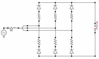
FIG. 38 Circuit diagram for EMTP simulation of three-phase rectifier
circuit.
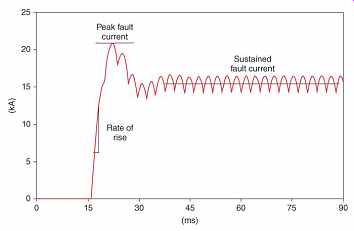
FIG. 39 Current-time curve of rectifier short-circuit current for fault
in DC system with appreciable inductance and resistance in the DC system, illustrating
the components of the fault current waveform.
The DC tests utilize a three-phase bridge rectifier. The characteristics of this device are that the open circuit DC output voltage is 1.35 times the AC line-line voltage. Thus for a 750 V AC source, approximately 1000 V of DC output voltage is produced. The current output of the rectifier has three modes, Modes 1-3.
Mode 1 is the normal mode where load is supplied. Mode 3 is the short-circuit mode, and Mode 2 is a region of either high overloads or low short-circuit currents.
The load regulation curve for a 70 kA fault in FIG. 40 shows that Mode 1 lasts until 75% voltage, Mode 2 as the voltage decreases from 75% to 43%, and Mode 3 is below 43% voltage.
In short-circuit tests, the voltage is near zero in Mode 3. In overload and endurance tests, the voltage is in Mode 1, as indicated by the 1200 A load current shown. The load regulation curve in FIG. 41 shows the response for a low fault current of 1.1 kA.
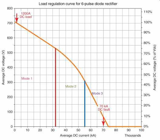
FIG. 40 Load regulation curve for 70 kA output.
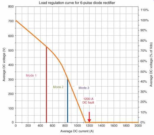
FIG. 41 Load regulation curve for 1.1 kA output.
Endurance tests are performed at 100% of the rated current, with the values for various breaker ratings listed in TABLE 24. The no-load voltage of the test circuit should not be less than 100% and greater than 105% of the rated voltage. The L/R time constant of the test circuit should not be less than 0.02 s or exceed 0.06 s. The test fuse should be rated 30 A with a voltage rating equal to or greater than that of the device under test, and a (#10 AWG) wire not longer than 1.8 m (6 ft). The breakers are switched on and off at the rate of one operation every 2 min. The circuit breaker must remain closed for at least 300 ms during each test. Tests may be grouped in sequences of no fewer than 120 operations. A mechanical endurance test must also be performed, with 20% of the operations listed for the energized endurance test.
The short-circuit tests are performed at high values of current, with the values for various breaker ratings listed in TABLE 11. The short-circuit test for breakers used on solid-state rectifier applications also includes a test of peak current as part of the same operation. The no-load voltage of the test circuit should not be larger than the rated maximum voltage of the breaker under test. The L/R time constant of the test circuit is not specified directly, but specific values of and for different tests are given in IEEE (2009a). The test fuse should be rated 30 A with a voltage rating equal to or greater than that of the device under test, and a (#10 AWG) wire not longer than 1.8 m (6 ft).
11.7 Testing of Low-Voltage Switchgear and Controlgear According to IEC Standard 60947-1
IEC Standard 60947-1 (IEC, 2011b) covers all types of switchgear and controlgear up to 1000 V AC and 1500 V DC. The general rules of the switchgear and controlgear standard apply to circuit breakers with some modifications as detailed in the specific circuit breaker standards. IEC Standard 60947-2 (IEC, 2013a) covers all types of circuit breakers up to 1000 V AC and 1500 V DC. This standard covers all types of low-voltage circuit breakers except those covered in the following standards:
• IEC 60947-4-1 relating to circuit breakers used for across-the-line starters for motors.
• IEC 60898 relating to circuit breakers used in households and similar installations.
• IEC 60934 relating to circuit breakers used in equipment such as electrical appliances.
The standard IEC voltage ratings (IEC, 2009b) are listed in Tables 31 and 32. The standard IEC current ratings (IEC, 1999) are listed in TABLE 33. All rated currents both continuous-current and short-circuit-current ratings, are chosen from the standard currents in TABLE 33. IEC Standard 60947-1 tests of low-voltage AC switchgear and controlgear are to be performed with the test frequency being in the range ±25% of the rated frequency of the equipment.
TABLE 31 Standard Nominal Rated AC Voltages for IEC Rated Equipment
TABLE 32 Standard DC Voltages for IEC Rated Traction Systems
TABLE 33 Standard IEC Current Ratings for Equipment
For low-voltage circuit breakers covered under IEC Standard 60497-1 (IEC, 2011b), the tests include the following:
1. Overload performance tests verify the circuit breaker can withstand repeated overloads.
2. Operational performance capability (endurance) tests verify that the circuit breaker can withstand multiple switching operations at 100% of the rated current.
3. Short-circuit making and breaking capacity tests verify that the circuit breaker can safely close on (make) and interrupt (break) its rated short-circuit current in the case of a short circuit.
Each type of test is conducted in specific test circuits according to the voltage and current ratings, number of poles (individual breaker units within the overall case), and circuit type (single-phase and three-phase). Each test also has a specific sequence of operations for repeated closings of the circuit breaker being tested.
Test circuits are given in FIG. 43 for overload and operational performance tests, and in FIG. 44 for short-circuit tests. The fusible element, f, in FIG. 43 and FIG. 42 is rated for 1500 A ± 10%, and consists of a round copper conductor with a diameter of 0.8 mm, and a length of 50 mm, or equivalent.
The resistor limits the prospective fault current in fuse f to 1500 A.
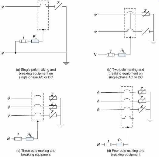
FIG. 42 Overload and operational performance making and breaking test
circuits based on IEC 60947-1 (IEC, 2011b). (a) Single-pole making and breaking
equipment on single-phase AC or DC; (b) two-pole making and breaking equipment
on single-phase AC or DC; (c) three-pole making and breaking equipment; (d)
four-pole making and breaking equipment.
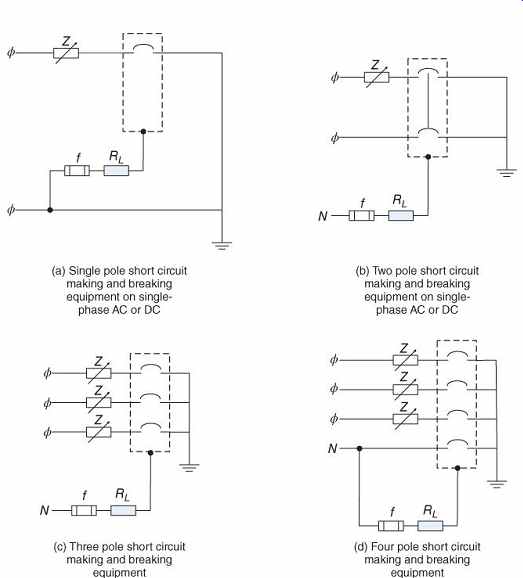
FIG. 43 Short-circuit making and breaking test circuits, based on IEC
60947-1 (IEC, 2011b). (a) Single-pole, short-circuit making and breaking equipment
on single-phase AC or DC; (b) two-pole, short-circuit making and breaking equipment
on single-phase AC or DC; (c) three-pole, short-circuit making and breaking
equipment; (d) four-pole, short-circuit making and breaking equipment.
11.8 Testing of Low-Voltage AC and DC Circuit Breakers
According to IEC Standard 60947-2 IEC Standard 60947-2 tests of low-voltage AC circuit breakers are to be performed with the test frequency being in the range of ±5% of the rated frequency of the circuit breaker. The overload tests are set up as shown in FIG. 43 and the short-circuit tests as in FIG. 44. The short-circuit and overload test currents, AC power factors, and DC time constants for circuit breakers tested in accordance with IEC 60947-2 are listed in TABLE 34, taken from Table 11 of (IEC, 2013a).
TABLE 34 IEC Short-Circuit Tests for Switchgear and Controlgear at Rated Short-Circuit Amperes
Overload performance tests for AC circuit breakers are performed 600% of the rated current for AC circuit breakers and 250% or the rated current for DC circuit breakers. The no-load voltage of the test circuit should not be less than 100% and greater than 105% of the rated voltage, while the voltage with the overload value of current should not be less than 65% of the rated voltage. Tests are performed at a lagging power factor of no more than 50% for AC circuit breakers, or a time constant of 2.5 ms for DC circuit breakers, as listed in TABLE 35. The test operating rates for the overload performance test are for a total of 12 operations, at the rates given in TABLE 36. The 12 operations consist of nine manual and three automatic openings, unless the circuit-breaker short-circuit trip setting is less than the test current, requiring that all openings be automatic. The breaker should be kept closed for long enough in each manual cycle for the full current to be reached, but not longer than 2s.
TABLE 35 IEC Short-Circuit Tests and Overload Test Currents for Circuit Breakers
TABLE 36 Operating Rates for Overload Performance and Operational Performance Tests According to IEC 60947-2
The operational performance capability tests are performed at 100% of the rated current. The no-load voltage of the test circuit should not be less than 100% and greater than 105% of the rated voltage. The voltage of the test circuit with load should be greater than 80% of the rated voltage. The test frequency should be in the range 45-62 Hz. Tests are performed at a lagging power factor of not more than 80% for AC circuit breakers or a time constant of 2.0 ms for DC circuit breakers, as listed in TABLE 35.
The test operating rates and number of operations for the operational performance test are given in TABLE 36.
The short-circuit current tests are performed at the rated values of short-circuit making and breaking current. The no-load voltage of the test circuit should not larger than the rated maximum voltage of the breaker under test. A tolerance of ±5% of the rated frequency applies to the test frequency. The short-circuit current tests are performed at a lagging power factor as shown in TABLE 35. The power frequency recovery voltage is the voltage across the breaker contacts while it is opening. The power frequency recovery voltage should be 105% of the rated maximum voltage of the breaker under test.
11.9 Testing of Circuit Breakers Used for Across-the-Line Starters for Motors According to IEC Standard 60947-4-1
IEC Standard 60947-4-1 (IEC, 2009c) tests of low-voltage AC and DC contactors and AC motor starters are to be performed with the test frequency being 50 Hz for devices rated at 50 Hz or 60 Hz. While the standard covers many types of contactors and starters, only two categories of devices are considered here, AC-3 and AC-4 for operation of squirrel cage motors.
Category AC-3 covers starting motors and disconnecting motors while running. Category AC-4 covers starting, plugging and inching.
The overload tests are set up as shown in FIG. 40. The overload test currents are eight times the rated operational current for contactors and starters rated 630 A or less, and six times for those rated above 630 A. The duration of the overload test is 10 s and shall be performed one time.
The operational performance capability tests are performed at 200% of the rated current for category AC-3 and 600% for category AC-4. The no-load voltage of the test circuit should not be less than 100% and greater than 105% of the rated voltage. Tests are performed at a lagging power factor of 45% for devices rated 100 A or less and 35% for those rated above 100 A. The test is performed for 6000 operations, with intervals between tests as shown in TABLE 37.
TABLE 37 Time Interval Between Operations for Making and Breaking Tests of Contactors and Starters IEC 60947-4-1
The short-circuit current tests are performed at the rated values of short-circuit making and breaking current. The no-load voltage of the test circuit should not be larger than the rated maximum voltage of the breaker under test.
The short-circuit current tests are performed at a lagging power factor as shown in TABLE 34.
The power frequency recovery voltage is the voltage across the breaker contacts while it is opening. The power frequency recovery voltage should be 105% of the rated maximum voltage of the breaker under test. The fusible element, f, in Figures 42 and 43 consists of a round copper conductor with a cross-sectional area of and a length of 1.2-1.8 m, connected to the neutral. The resistor limits the prospective fault current in fuse f to 1500 A.
11.10 Testing of Circuit Breakers Used in Households and Similar Installations According to IEC Standard 60898-1 and -2
IEC Standard 60898-1 (IEC, 2003a) and 60898-2 (IEC, 2003b) cover tests of low-voltage AC and DC circuit breakers for overcurrent protection for household and similar installations. Circuit breakers under this standard with more than one pole are not required to have overcurrent tripping mechanisms on each pole. A pole with an overcurrent tripping mechanism is referred to as a protected pole. The tests may be performed at "any convenient voltage." These standards cover circuit breakers of the following voltage ratings for AC:
• 120, 230, 240, and 400 V, single- or three-phase
• 120/240 V, single-phase
• 230/400 V, single- or three-phase.
These standards cover circuit breakers of the following voltage ratings for DC:
• 125 or 220 V, single pole
• 220/440 or 125/250 V, two pole.
Preferred values of the rated current are listed in TABLE 38.
TABLE 38 Preferred Values of Rated Current (A) Per IEC 60898-1
Mechanical and electrical endurance tests are performed at 100% of the rated current. The test frequency should be in the range 45-62 Hz.
Tests are performed at a lagging power factor between 85% and 90% for AC circuit breakers, or a time constant of 4 ms ± 10% for DC circuit breakers, except that DC breakers marked T15 are tested at a time constant of 15 ms. The DC test current should have a ripple (?) of no more than 5%. The endurance test consists of 4000 making and breaking operations (operating cycle). Circuit breakers less than or equal to 32 A are tested at a rate of 240 per hour, spaced at least 13s apart. Circuit breakers greater than 32 A are tested at a rate of 120 per hour, spaced at least 28 s apart.
The-short circuit current tests are performed at either 500 A, or 10 times the rated current, and at 1500 A. Circuit breakers rated above 1500 A short-circuit capacity, , are subject to testing of the "service short-circuit capacity" and at the "rated short-circuit capacity." Standard and preferred values of rated short-circuit capacity are listed in TABLE 39.
The service short-circuit capacity, , is the breaking capacity when the circuit breaker is loaded at 85% of its "non-tripping current," , which is the highest value of current where the circuit breaker will not trip. The ratio between and is called " " and is listed in Table 40.
Short-circuit test currents have a tolerance of ±5% of the specified current. The frequency tolerance for the short circuit test is ±5% of the rated frequency.
TABLE 39 Standard and Preferred (*) Values of Rated Short Circuit Capacity (A) per IEC 60898-1
TABLE 40 Ratio "k" Between Service Short-Circuit Capacity and Rated Short-Circuit Capacity, Per IEC 60898-1
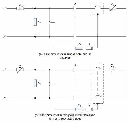
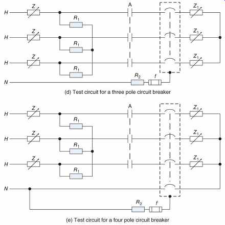
FIG. 44 Test circuits based on IEC 60898 (IEC, 2011b) ac circuit breakers
for households and similar installations. (a) Test circuit for a single-pole
circuit breaker; (b) test circuit for a two-pole circuit breaker with one protected
pole; (c) test circuit for a two-pole circuit breaker with two protected poles;
(d) test circuit for a three-pole circuit breaker; (e) test circuit for a four-pole
circuit breaker.
Circuits for testing of one-, two-, three-, and four pole circuit breakers are shown in FIG. 44. The following circuit elements are identified:
• A is the making switch.
• is the adjustable impedance to set the short-circuit current at the rated value.
• is an adjustable impedance to reduce the short-circuit current below its rated value.
• is a resistor selected for a current of 10 A at the applied voltage.
• is the "hot" wire of the source.
• is the neutral wire of the source.
• is a test fuse, consisting of a copper wire 50 mm or longer, having a diameter of 0.1 mm for a circuit breaker tested in free air, or 0.3 mm for a circuit breaker tested in an enclosure.
• is a resistor.
The power frequency recovery voltage is the voltage across the breaker contacts while it is opening. The power frequency recovery voltage should be 105%, with a tolerance of ±10%, of the rated maximum voltage of the breaker under test.
Short-circuit tests are performed at a lagging power factor between 20% and 98% for AC circuit breakers, as listed in TABLE 41, or a time constant of 4 ms ± 10% for DC circuit breakers, except that DC breakers marked T15 are tested at a time constant of 15 ms. The DC test current should have a ripple (?) of no more than 5%. Tests are performed for a variety of make and break sequences and repetition rates as specified in the standard.
TABLE 41 Test Power Factor for AC Short-Circuit Tests, Per IEC 60898-1
11.11 Testing of Circuit Breakers Used in Equipment such as Electrical Appliances
According to IEC Standard 60934 IEC Standard 60934 (IEC, 2013b) covers tests of low-voltage AC and DC circuit breakers for overcurrent protection for use within equipment for household and similar installations. These devices are similar to the supplementary protectors discussed under UL Standard 1077. Under this standard, circuit breakers with more than one pole are not required to have overcurrent tripping mechanisms on each pole. A pole with an overcurrent tripping mechanism is referred to as a protected pole. The preferred rated voltages are listed in TABLE 42. The rated currents are up to and including 125 A. The rated frequencies for the devices covered here are 50, 60, and 400 Hz.
TABLE 42 Rated Voltages for Circuit Breakers Under IEC 60934
Tests are performed with tolerances of ±5% on frequency and voltage, and -0%/+5% on test current. Endurance (rated current), overload, and short-circuit tests are performed for a wide variety of operations, AC power factors, and DC time constants, as specified in the standard.
Short-circuit current tests are performed at the "rated switching capacity" and the "rated short circuit capacity." The rated switching capacity is the short-circuit making and breaking current.
The rated short-circuit capacity is six times the rated current for AC and Four times for DC, except that it shall not be larger than 3000 A.
Short-circuit current tests are also performed at the "rated conditional short-circuit current," which is the short-circuit withstand current when the device is protected by a short-circuit protective device, such as an upstream fuse or circuit breaker.
Circuits for testing of one-, two-, three-, and four-pole circuit breakers are shown in FIG. 45. The circuit elements are identified as in FIG. 44, except for the fuse, f: is a test fuse, consisting of a copper wire 50 mm or longer, having a diameter of 0.1 mm.
The power frequency recovery voltage is the voltage across the breaker contacts while it is opening. The power frequency recovery voltage should be 105%, with a tolerance of ±10%, of the rated maximum voltage of the breaker under test.
Tests at the rated conditional short-circuit current are performed at a lagging power factor between 85% and 98% for AC circuit breakers as listed in TABLE 43, or a time constant of 2.5 or 5 ms for DC circuit breakers as listed in 2003b). Tests are performed for a variety of make and break sequences and repetition rates as specified in the standard.
TABLE 44. Tests at currents over 3000 A are performed according to IEC Standard 60898 (IEC, 2003a.
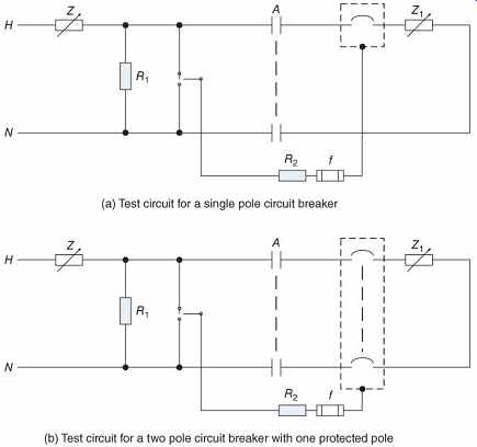
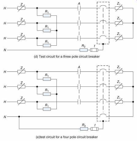
FIG. 45 Test circuits based on IEC 60934 (IEC, 2013b). (a) Test circuit
for a single-pole circuit breaker; (b) test circuit for a two-pole circuit
breaker with one protected pole; (d) test circuit for a three-pole circuit
breaker; (e) test circuit for a four-pole circuit breaker.
TABLE 43 Test Power Factor for AC Conditional Short-Circuit Current Tests, Per IEC 60934
TABLE 44 Test Time Constants for DC Conditional Short-Circuit Current Tests, per IEC 60934
12. Testing of High-Voltage Circuit Breakers
High-voltage circuit breakers, greater than 1 kV, may be tested according IEEE Standard C37.09-1999 (IEEE, 1999a) or a similar IEC standard. The ratings of the high-voltage circuit breakers tested under C37.09 are defined in IEEE Standard C37.04 (IEEE, 1999b). Three types of tests are set forth:
Design tests are performed to demonstrate that a circuit breaker design can meet the requirements specified in C37.04.
Production tests are factory tests, which are part of the manufacturing process.
Conformance tests are generally performed on-site to demonstrate that a circuit breaker meets certain requirements.
Production and conformance tests will not be described here. The design tests include the following:
1. Maximum-voltage tests are considered to be passed if the circuit breaker is successfully tested for short-circuit and other tests at its rated maximum voltage.
2. Power frequency tests are considered to be passed if the circuit breaker is successfully tested at its rated frequency ±10%, or at the rated frequency if allowed.
3. Continuous-current-carrying tests require that the circuit breaker temperature should not increase by more than 1 °C over an ambient temperature between 10°C and 40°C for three separate 30 min tests. The resistance of the closed circuit breaker is also measured, using a test current of at least 1A, up to the rated continuous current.
4. Dielectric withstand tests are for power frequency dielectric withstand, lightning impulse, and chopped wave tests, as specified in IEEE Standard C37.06 (IEEE, 2009a).
5. Standard operating duty (standard duty cycle) tests are performed at the rated current for selected duty cycles.
6. Interrupting time tests measure the total of the contact parting time plus the arcing time.
7. Transient recovery voltage (TRV) tests determine whether a circuit breaker can withstand a certain voltage while the contacts are opening as specified in IEEE Standard C37.06. This is done as part of the short circuit tests.
8. Short-circuit current interrupting tests are conducted over a wide variety of test conditions to ensure that the circuit breaker can interrupt short circuits as specified in IEEE Standard C37.04.
9. Load current switching tests demonstrate the ability of the circuit breaker to switch specified load currents over given duty cycles.
10. Capacitor switching current tests demonstrate the ability of the circuit breaker to switch specified capacitor banks or highly capacitive lines and cables over given duty cycles.