AMAZON multi-meters discounts AMAZON oscilloscope discounts
[Note: "Tables" and various equations (denoted by "e.") are not yet avail., but coming soon.]
(cont. from part 1)
11. Testing of Low-Voltage Circuit Breakers
In order for circuit breakers to be applied in a safe manner, samples of each type must be able to pass exhaustive testing for multiple switching operations (endurance tests), moderate degrees of overcurrent (overload tests), and high degrees of overcurrent (interrupting tests). The test procedures are specified in various standards published by standards bodies regulating the particular types and ratings of circuit breakers built according to those standards. Examples include the worldwide International Electrotechnical Commission (IEC) and the Institute of Electrical and Electronic Engineers (IEEE). Bodies specific to the United States include the ANSI, National Electrical Manufacturers Association (NEMA), and Underwriters Laboratories (UL). In many cases, the manufacturer's testing program must be observed by a representative of the standards-making body in order that the parts may be certified as being tested in conformance with the standards. The following standards are widely used in the testing of low-voltage (<1000 V) AC and DC circuit breakers:
1. UL489 Eleventh Edition (UL, 2009) September 1, 2009, UL Standard for Safety for Molded-Case Circuit Breakers, Molded-Case Switches and Circuit-Breaker Enclosures.
2. UL 1077 Sixth Edition (UL, 2005) July 14, 2005, UL Standard for Safety for Supplementary Protectors for Use in Electrical Equipment.
3. UL 1008 Sixth Edition (UL, 2011) April 15, 2011, UL Standard for Safety for Transfer Switch Equipment.
4. ANSI C37.50-1989 (ANSI, 1989) American National Standard for Switchgear- Low-Voltage AC Power Circuit Breakers Used in Enclosures - Test Procedures.
5. IEC 60947
a. IEC 60947-1 (IEC, 2011b) Edition 5.1 2011-03, Low-voltage switchgear and controlgear-Part 1: General rules.
b. IEC 60947-2 (IEC, 2013a) Edition 4.2 2013-01, Low-voltage switchgear and controlgear-Part 2: Circuit-breakers.
6. IEC 60898
a. IEC 60898-1 (IEC, 2003a) Edition 1.2, 2003-07, Electrical accessories-Circuit-breakers for overcurrent protection for household and similar installations-Part 1: Circuit-breakers for a.c. operation.
b. IEC 60898-2 (IEC, 2003b) Edition 1.1, 2003-07, Edition 1:2000 consolidated with amendment 1:2003, Electrical accessories--Circuit-breakers for overcurrent protection for household and similar installations-Part 2:Circuit-breakers for a.c. and d.c. operation.
7. IEC 60934 (IEC, 2013b), Edition 3.2 2013-01, circuit-breakers for equipment (CBE).
Owing to the large number of types of circuit breakers and testing standards, the discussion which follows will only cover the highlights of some of the specified procedures. Low-voltage circuit breakers are tested for various types of duty and duty cycles appropriate for each type of breaker.
Due to the complexities of these test procedures, they are only summarized here. For anyone who intends to test circuit breakers or to evaluate tests of circuit breakers, the latest version of the applicable standard should be referred to.
11.1 Testing of Low-Voltage Molded-Case Circuit Breakers
According to UL Standard 489 For MCCBs covered in UL 489-2009 (UL, 2009), the tests include the following:
1. Overload tests verify the circuit breaker can withstand repeated overloads at 600% of the rated currents.
2. Endurance tests verify that the circuit breaker can withstand multiple switching operations at 100% of the rated current.
3. Interrupting tests verify that the circuit breaker can safely interrupt its rated short-circuit current in the case of a short circuit.
Each type of test is conducted in specific test circuits according to the voltage and current ratings, number of poles (individual breaker units within the overall case), and circuit type (single-phase and three-phase). UL 489 provides diagrams of each type of test circuit to be used. Each test also has a specific sequence of operations for repeated closings of the circuit breaker being tested.
UL 489 tests of AC MCCBs are designed for breakers rated 50-60 Hz, with the test frequency being in the range of 48-62 Hz.
Circuit breakers have standard ampere ratings (continuous-current-carrying capability) as specified in the Article 240.6 (A) of the NEC (NFPA, 2014), listed in TABLE 5. The standard voltage ratings for MCCBs are listed in TABLE 6 for AC (both single and three-phase) and DC. The interrupting ratings of the circuit breakers, defined as "the highest RMS symmetrical current at rated voltage that a device is intended to interrupt under standard test conditions" are many times larger than their ampere ratings. For MCCBs rated under UL 489, the interrupting ratings range from 7.5 to 200 kA (TABLE 7).
TABLE 5 Standard Ampere Ratings for Circuit Breakers
TABLE 6 Voltage Ratings for MCCBs from UL 489 Clause 8.2
TABLE 7 Applicable Current-Interrupting Ratings (AC or DC) From UL 489, Table 8-1
The overload tests are performed at 600% of the rated current, with the values for various breaker ratings listed in TABLE 8. Test circuits for overload tests are shown in FIG. 12.
The no-load voltage of the test circuit should be in the range 100-105% of the rated voltage, while the overload voltage with 600% current should be in the range 85-115% of the rated voltage. If certain requirements for the recovery voltage (the voltage across the circuit breaker when it is opening) are met, then the ±15% requirement may be waived. Tests are performed at a lagging power factor from 45% to 50% for AC circuit breakers, as shown in FIG. 13, except that some tests of two-pole and single-pole circuit breakers are performed at lagging a power factor of 75-80%. For DC circuit breakers, the L/R time constant of the test circuit should not exceed 0.003 s, as shown in FIG. 14. The test fuse should be rated 30 A with a voltage rating equal to or greater than that of the device under test, and a (#10 AWG) wire not longer than 1.8 m (6 ft). The timing sequences for these tests are listed in TABLE 9, and shown diagrammatically in Figures 15-19. The breakers are only switched on for a very short time in each test, as no particular duration is specified.
TABLE 8 Overload Tests at 600% of Rated Amperes (UL 489, Clause. 7.1.3.7-8 and 7.1.3.14)
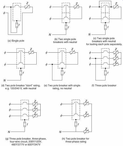
FIG. 12 Overload test circuits based on UL 489 (UL, 2009). (a) Single
pole; (b) two single-pole breakers with neutral for testing each pole separately;
(c) two single-pole breakers with neutral; (d) two-pole breaker "slant" rating,
for example, 120/240 V, with neutral; (e) two-pole breaker with single rating,
no neutral; (f) three-pole breaker; (g) three-pole breaker, three-phase, four-wire
circuit, 208v/120 V, 480v/277 V, or 600Y/347 V; (h) two-pole breaker for three-phase
rating.
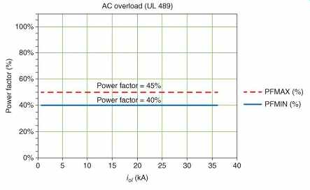
FIG. 13 AC overload power factors.
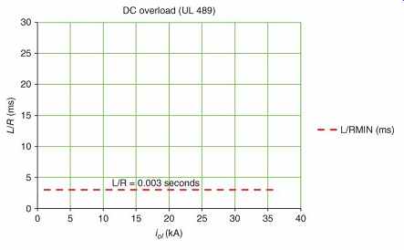
FIG. 14 DC overload time constant.
TABLE 9 Operations for Overload Test Operations (600% of Rated Current Unless Otherwise Noted)
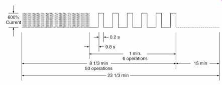
FIG. 15 Overload test, =100 A frame (not to scale).
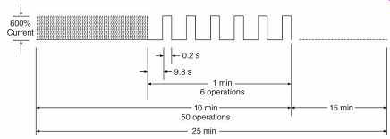
FIG. 16 Overload test, 101-225 A frame (not to scale).
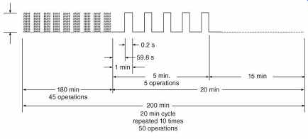
FIG. 17 Overload test, 226-1600 A frame (not to scale).
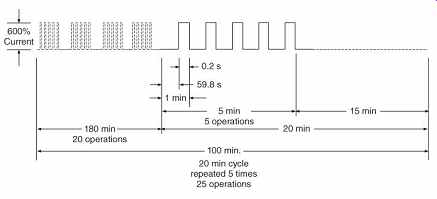
FIG. 18 Overload test, 1601-2500 A frame (not to scale).
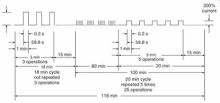
FIG. 19 Overload test, 2501-6000 A frame (not to scale).
Endurance tests are performed at 100% of the rated current, with the values for various breaker ratings listed in TABLE 5. The voltage of the test circuit with load should be greater than 97.5% of the rated voltage. Test circuits for endurance tests are shown in FIG. 20.
Tests are performed at a lagging power factor from 75% to 80% for AC circuit breakers, as shown in FIG. 21. For DC circuit breakers, the L/R time constant of the test circuit should not exceed 0.003 s, as shown in FIG. 22.
The test fuse should be rated 30 A with a voltage rating equal to or greater than that of the device under test, and a (#10 AWG) wire not longer than 1.8 m (6 ft). The timing sequences for these tests listed in TABLE 10, and shown diagrammatically in Figures 23-28. The breakers are only switched on for a very short time in each test, as no particular duration is specified.
TABLE 10 Operations for Endurance Test Operations (100% of Rated Current)
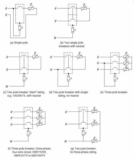
FIG. 20 Endurance test circuits based on UL 489 (UL, 2009). (a) Single
pole; (b) two single-pole breakers with neutral; (c) two-pole breaker "slant" rating,
for example, 120/240 V, with neutral; (d) two-pole breaker with single rating,
no neutral; (e) three-pole breaker; (f) three-pole breaker, three-phase, four-wire
circuit, 208Y/120 V, 480Y/277 V, or 600Y/347 V; (g) two-pole breaker for three-phase
rating.
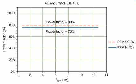
FIG. 21 AC endurance power factors.
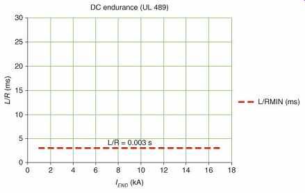
FIG. 22 DC endurance time constant.
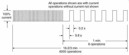
FIG. 23 Endurance test, 100 A frame (not to scale).
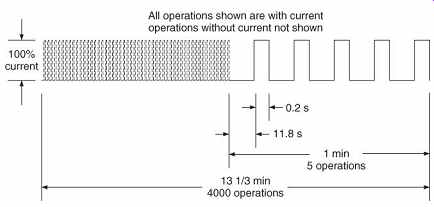
FIG. 24 Endurance test, 150 A and 225 A frames (not to scale).
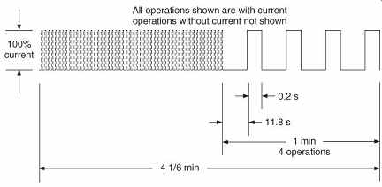
FIG. 25 Endurance test, 600 A frame (not to scale).
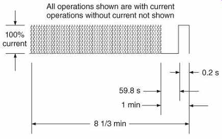
FIG. 26 Endurance test, 800 A frame (not to scale).
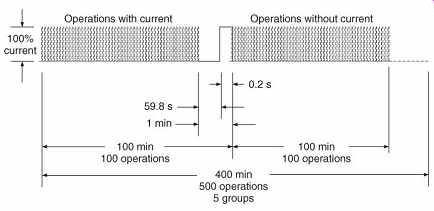
FIG. 27 Endurance test, 1200 A and 2500 A frames (not to scale).
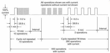
FIG. 28 Endurance test, 6000 A frame (not to scale).
Interrupting tests are performed at high values of current, with the values for various breaker ratings listed in TABLE 11. Test circuits for interrupting tests are shown in FIG. 29.
The no-load voltage of the test circuit, both AC and DC tests, should be in the range 100-105% of the rated voltage. Tests are performed at a lagging power factor from 45% to 50% for AC circuit breakers tested at 10 kA or less, 25-30% for 10.001-20 kA, and 15-20% for test currents greater than 20 kA, as shown in FIG. 30.
For DC circuit breakers, the L/R time constant of the test circuit should be greater than or equal to 0.003 s if the test current is less than or equal to 10 kA, as shown in FIG. 31. If the test current exceeds 10 kA, the DC time constant should be greater than or equal to 0.008 s. The timing sequences for these tests are listed in TABLE 12, and shown diagrammatically in FIG. 32. The test fuse should be rated 30 A with a voltage rating equal to or greater than that of the device under test, and a (#10 AWG) wire not longer than 1.8 m (6 ft).
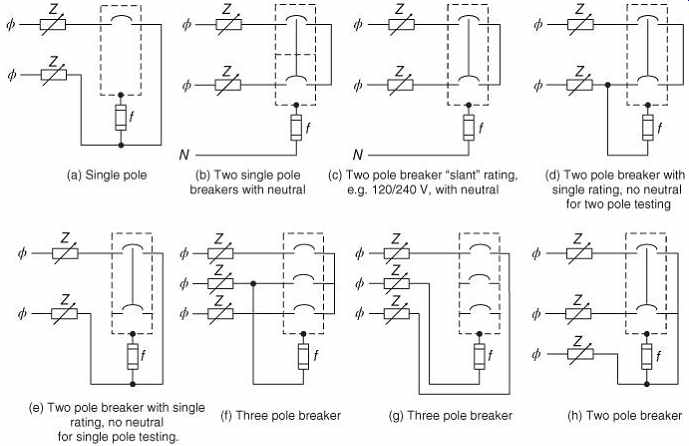
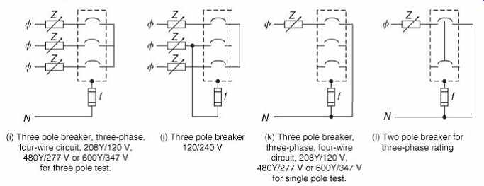
FIG. 29 Interrupting test circuits based on UL 489 (UL, 2009). (a) Single
pole; (b) two single-pole breakers with neutral; (c) two-pole breaker "slant" rating,
for example, 120/240 V, with neutral; (d) two-pole breaker with single rating,
no neutral for two pole testing; (e) two-pole breaker with single rating, no
neutral for single pole testing; (f) three-pole breaker; (g) three-pole breaker;
(h) two-pole breaker; (i) three-pole breaker, three-phase four-wire circuit,
208Y/120 V, 480Y/277 V, or 600Y/347 V for three pole test; (j) three-pole breaker
120/ 240 V; (k) three-pole breaker, three-phase, four-wire circuit, 208Y/120
V, 480Y/277 V, or 600Y/347 V for single pole test; (l) two pole breaker for
three-phase rating.
TABLE 11 Test Currents, Power Factors, and DC Time Constants for Interrupting Tests
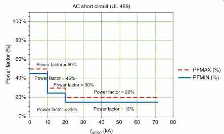
FIG. 30 AC interrupting power factors.
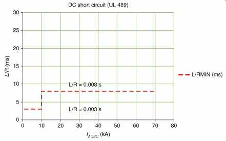
FIG. 31 DC interrupting time constants.
TABLE 12 Operations for Interrupting Test Operations
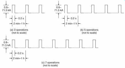
FIG. 32 Interrupting tests (not to scale).
(a) Three operations (not to scale); (b) five operations (not to scale); and (c) seven operations (not to scale).
11.2 Testing of Low-Voltage Molded-Case Circuit Breakers for Use With Uninterruptible Power Supplies According to UL Standard 489
Low-voltage MCCBs used with uninterruptable power supplies (UPS) are subject to special test conditions. All other aspects of these tests are as previously described. The tests are to be applied at the maximum voltages shown in TABLE 13. In the overload test, the applied current is only 200% instead of 600% of the rated current. The specifications for the overload test are shown in TABLE 14. The specifications for the endurance test are shown in TABLE 15.
TABLE 13 Maximum Voltage for Tests to be Applied for Breakers Used in UPS
TABLE 14 Overload Test for Breakers Used in UPS
TABLE 15 Endurance Test for Breakers Used in UPS
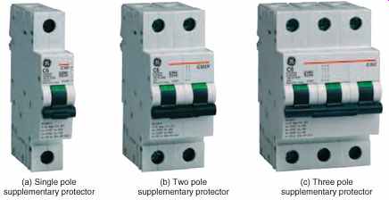
FIG. 33 Supplementary protectors for use in electrical equipment according
to UL Standard 1077 (General Electric Company). (a) Single-pole supplementary
protector; (b) two-pole supplementary protector; and (c) three-pole supplementary
protector.
11.3 Testing of Supplementary Protectors for Use in Electrical Equipment According to UL Standard 1077
A supplementary protector, sometimes called a miniature circuit breaker, is similar to a molded-case circuit breaker, but is designed to be used inside an appliance or other piece of equipment. Single-pole, two-pole, and three-pole supplementary protectors are shown in FIG. 33 (General Electric Company, 2007). As such, they are important in protecting against appliance fires and other hazards to people and property. The definition of a supplementary protector is given in the UL Standard for Safety for Supplementary Protectors for Use in Electrical Equipment, UL Standard 1077 (UL, 2005):
"A manually resettable device designed to open the circuit automatically on a predetermined value of time versus current or voltage within an appliance or other electrical equipment. It is permitted to be provided with manual means for opening or closing the circuit." Supplementary protectors are subjected to overload, endurance, and short circuit tests, similar to molded-case circuit breakers.
For supplementary protectors covered in UL 1077-2005 (UL, 2005), the tests include the following:
1. Overload tests verify the supplementary protectors and can withstand repeated overloads at specified multiples of the rated current.
2. Endurance tests verify that the supplementary protectors can withstand multiple switching operations at 100% of the rated current.
3. Short circuit tests verify that the supplementary protector can safely open and close on its rated short circuit current in the case of a short circuit.
Each type of test is conducted in specific test circuits according to the voltage and current ratings, number of poles (individual supplementary protectors within the overall case), and circuit type (single-phase and three-phase). UL 1077 provides diagrams of each type of test circuit to be used. Each test also has a specific sequence of operations for repeated closings of the supplementary protector being tested.
UL 1077 tests of AC supplementary protectors are designed for devices rated 60 Hz, or the specified operating frequency of the device. For a 60 Hz device, the test frequency should be in the range of 60 ± 12 Hz. The short circuit current ratings of the supplementary protectors, if present, are marked on the device, along with code letters indicating whether the short circuit test was performed with or without series overcurrent protection.
The overload tests are performed at multiples of the rated current, with the values for various applications listed in TABLE 16. Test circuits for overload tests are shown in FIG. 34.
The open-circuit voltage of the test circuit should be in the range of 100-110% of the rated voltage. The closed-circuit voltage of the test circuit should be in the range of 90-110% of the rated voltage, except in special circumstances where it may be as low as 85%. Tests are performed at a lagging power factor from 45% to 50% for supplementary protectors for AC motors, as shown in TABLE 16. The test fuse should be rated 30 A with a voltage rating equal to or greater than that of the device under test, and a (#10 AWG) wire not longer than 1.8 m (6 ft). The overload test occurs for 50 repetitions in a sequence of on for 1 s and off for the following 9 s, followed by 35 cycles of automatic closing and opening operation.
TABLE 16 Overload Test Currents and Power Factor for Supplementary Protectors
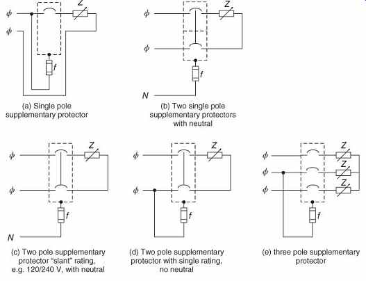
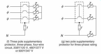
FIG. 34 Overload and endurance test circuits for supplementary protectors
based on UL 1077 (UL, 2005). (a) Single-pole supplementary protector; (b) two
single-pole supplementary protectors with neutral; (c) two-pole supplementary
protector "slant" rating, 120/240 V, with neutral; (d) two-pole supplementary
protector with single rating, no neutral; (e) three-pole supplementary protector;
(g) three-pole supplementary protector, three-phase, four-wire circuit, 208Y/
120 V, 480Y/277 V or 600Y/347 V; (h) two-pole supplementary protector for three-phase
rating.
The endurance tests are performed at the rated current. Test circuits for endurance tests are shown in FIG. 34. The open-circuit voltage of the test circuit should be in the range 100-105% of the rated voltage. The closed-circuit voltage of the test circuit should be in the range 90-110% of the rated voltage, except in special circumstances where it may be as low as 85%. Tests are performed at a lagging power factor from 75% to 80% for AC supplementary protectors. For DC supplementary protectors, a resistive load is used for testing. The test fuse should be rated 30 A with a voltage rating equal to or greater than that of the device under test and a (#10 AWG) wire not longer than 1.8 m (6 ft).
The endurance test occurs for 6000 repetitions of a sequence of on for 1 s and off for the following 9 s, which is a rate of six cycles per minute.
The short-circuit tests are performed at high values of current, with the values for supplementary protector ratings listed in TABLE 17. The test circuit for short-circuit tests is shown in FIG. 35. The circuit breaker "P" in the diagrams is the series overcurrent device (circuit breaker or fuse) which may be required.
The supplementary protector should be protected by an appropriate fuse or circuit breaker during the testing. The no-load voltage of the test circuit, both AC and DC tests, should be in the range 99-105% of the rated voltage.
AC tests are performed at a lagging power factor from 75% to 80%. For DC supplementary protectors, a resistive load should be used. The test fuse should be rated 30 A with a voltage rating equal to or greater than that of the device under test, and a (#10 AWG) wire not longer than 1.8 m (6 ft). The test is performed for three operations; the first operation is opening on a short circuit, while the subsequent two are closing on a short circuit.
TABLE 17 Short-Circuit Test Currents and Power Factor for Supplementary Protectors
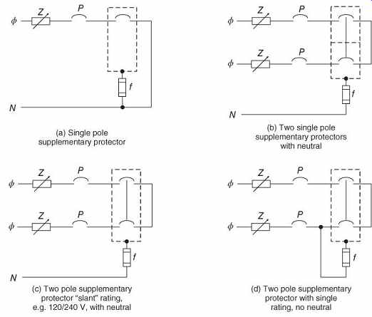
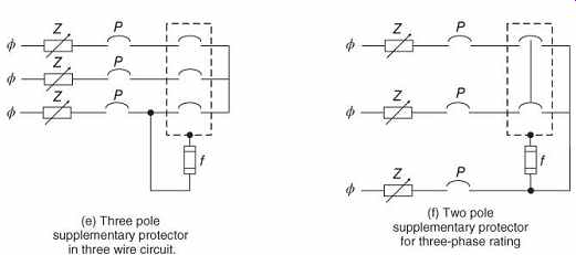
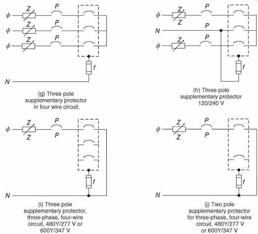
FIG. 35 Short-circuit test circuits for supplementary protectors based
on UL 1077 (UL, 2005). (a) Single-pole supplementary protector; (b) two single-pole
supplementary protectors with neutral; (c) two-pole supplementary protector "slant" rating,
for example, 120/240 V, with neutral; (d) two-pole supplementary protector
with single rating, no neutral; (e) three-pole supplementary protector in three
wire circuit; (f) two-pole supplementary protector for three-phase rating;
(g) three-pole supplementary protector in four wire circuit; (h) three-pole supplementary protector, 120/240 V; (i) three-pole supplementary protector, three-phase, four-wire circuit, 480Y/277 V or 600Y/347 V; (j) two-pole supplementary protector for three-phase, four-wire circuit, 480Y/277 V or 600Y/347 V.
11.4 Testing of Transfer Switch Equipment According to UL Standard 1008
Transfer switch equipment (UL, 2011) is used to manually or automatically transfer the power to a load from one source to another. An automatic transfer switch (ATS) is shown in FIG. 36 (General Electric Company, 2010).
These switches are important in protecting against the disruptions caused by loss of power to emergency and critical loads. A transfer switch will typically switch power between a normal (utility) supply and a source of backup power, such as a generator. The load is often protected during the time necessary to start the generator and transfer power by an uninterruptible power supply (UPS). The definition of a transfer switch is given in the National Electrical Code, NFPA 70-2014 (NFPA, 2014):
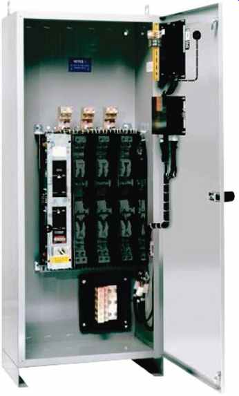
FIG. 36 Automatic transfer switch (Source: General Electric Company (2010)).
"An automatic or nonautomatic device for transferring one or more load conductor connections from one power source to another." Transfer switches are rated at a variety of low voltages for AC and DC operation, as listed in TABLE 18. The safety testing procedures for transfer switches is given in Transfer Switch Equipment, UL Standard 1008 (UL, 2011).
Transfer switches are subjected to overload and short-circuit tests, similar to supplemental protectors.
TABLE 18 Applicable Voltage Ratings for Transfer Switches
AC DC
120 125
240 250
480 600
600 -
Source: UL (2011).
For transfer switches covered in UL 1008-2011 (UL, 2011), these tests include the following:
1. Overload tests verify the transfer switch can withstand repeated overloads at specified multiples of the rated currents.
2. Endurance tests verify that the transfer switch can withstand multiple switching operations at 100% of the rated current.
3. Short-circuit withstand tests verify that the transfer switch can withstand a short circuit on the load terminals until the designated overcurrent protective device clears the fault. For transfer switches used in emergency or standby systems, the switch must be able to transfer during a short circuit on the load terminals to a neutral position or to the opposite source. Tests are performed on both the normal and alternate sources circuits.
Each type of test is conducted in specific test circuits according to the voltage and current ratings, number of poles (individual switches within the overall case), and circuit type (single-phase and three-phase). UL 1008 provides diagrams of the test circuits to be used. Each test also has a specific sequence of operations for repeated closings of the transfer switch being tested.
UL 1008 tests of AC transfer switches are designed for devices rated 50/60 Hz, or the specified operating frequency of the device. For a 50 or 60 Hz device, the test frequency should be 60 Hz. The short-circuit current ratings of transfer switches are marked on the device.
Standard short-circuit ratings are listed in TABLE 19.
TABLE 19 Short-Circuit Ratings for Transfer Switches
Overload tests are performed at multiples of the rated current, with the values for various applications listed in TABLE 20. The open-circuit voltage of the test circuit should be in the range 100-110% of the rated voltage. The closed-circuit voltage of the test circuit should be in the range 100-110% of the rated voltage, except in special circumstances where it may be as low as 85%. The tests are performed at a lagging power factor from 40% to 50% for transfer switches for AC motors, as shown in TABLE 20. The overload test duty cycles are shown in TABLE 21.
TABLE 20 Overload Test Currents and Power Factor for Transfer Switches
TABLE 21 Duty Cycles for Overload Tests of Transfer Switches
Endurance tests are performed at 100% of the rated current. The open-circuit voltage of the test circuit should be in the range 100-105% of the rated voltage. The closed-circuit voltage of the test circuit should be in the range 90-110% of the rated voltage, except in special circumstances where it may be as low as 85%.
Tests are performed at a lagging power factor from 75% to 80% for AC transfer switches. For DC transfer switches, a resistive load is used for testing. The endurance test duty cycles are shown in TABLE 22.
TABLE 22 Duty Cycles for Endurance Tests of Transfer Switches
Short-circuit withstand tests are performed at high values of current, with the values for various transfer switch ratings listed in TABLE 23. The test circuit for short-circuit withstand tests is shown in FIG. 37. The device should be protected by an appropriate fuse or circuit breaker during the testing. The fuse "P" in the diagram is the series overcurrent protective device which may be required for the tests. The no-load voltage of the test circuit, for both AC and DC tests, should be greater than or equal to the maximum rated voltage of the switch. The test fuse should be rated 30 A with a voltage rating equal to or greater than that of the device under test, and a (#10 AWG) wire not longer than 1.8 m (6 ft).
TABLE 23 Short-Circuit Test Currents and Power Factor for Transfer Switches
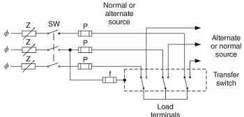
FIG. 37 Short-circuit test circuit for transfer switches based on UL
1008 (UL, 2011).
Three-pole supplementary protector.